The power front-seat headrests are often found inoperable in W124 cars because of repetitive manual adjustment of the headrest height. Let’s face the facts… most people don’t read owner’s manuals, are completely unaware that power headrests even exist, or don’t listen when you provide operational instruction. Manually adjusting the headrest height will eventually discombobulate the headrest’s internal mechanical components, leaving them piled in a heap at the base of the seatback.
There are usually three reasons for inoperable headrests:
1. Components have fallen apart
2. Components have broken
3. Electrical failure
My passenger seat headrest became inoperable. I held off from blaming my nephew until I could investigate. I had demonstrated how to adjust the headrest before leaving on a roadtrip. He only adjusted it once during the trip. A few days later, my sister was unable to adjust the headrest on the way home. A critical internal polymer component of the Adjusting Rail had broken. I think age & use was the actual culprit. A new Adjusting Rail unit can be had from parts.com for @ $20. I am fortunate to have a “Pickapart” yard a few minutes away. I liberated two units from a willing donor Benz.
This “HOW-TO” will show you how to inspect/repair an inoperable power headrest.
Reference Info:
Tools:
Philips head screwdriver
Body trim removal set
Straight Pick
Pliers
Gleitpaste
Here’s what to do if your headrests won’t work properly.
1. First verify that the headrest motor still works by listening to the lower seatback while pressing the door-mounted headrest switch up & down. Proceed with the FSM instructions if you can hear the motor running.
There is an electrical delivery issue to investigate if you do not hear the motor running.
2. Although stated in the FSM, it is not necessary to remove the head restraint in order to inspect/repair the control mechanisms. But if you want to remove the head rest…:
a. Using the control switch, tilt the seatback forward
b. Using the control switch, move the seatbottom forward so you have room to work from the rear seat
c. Open the sliding roof (for air, light & extra room to operate)
d. Ensure the head rest is seated in the fully “UP” position.
e. Press in the head restraint removal button located on the seatback. This will disengage the headrest from its slide rail connection. Look toward the upper left center of the seatback; you will see its circular outline on the seatback material.
f. Lift the head restraint straight up & out of the seatback.
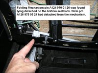
3. The FSM 91-190 procedure is pretty straight-forward. As instructed, remove the seatback cover & inspect what parts have accumulated at the bottom of the seatback. If you are lucky, the items only need to be reassembled. The Adjusting Rail has two knobs that fit into corresponding holes in the vertical metal guide rail of seat back structure. The knobs are held in place by a sliding lock plate.
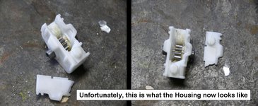
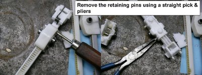
Make the effort to re-lube the Adjusting Rail’s Pinion Gear Housing internals with Gleitpaste or equivalent. The Gear Housing is a two-piece assembly made of a white polymer material pinned together with two pins of the same material. To properly lube the gear, or if the Housing has separated from the rail, separate the housing by removing the pins. The pins can be pushed out using a straight pick or equivalent. Place the rail back within the housing & pin the housing back together.
Within the housing is a metallic gear. A spring shaft fits into the gear on one end & the electric motor on the other end. The midsection of the shaft fits thru a loop attached to the opposite vertical metal guide rail structure of the seatback. Make sure the shaft is fit thru this loop. The loop holds the rotating shaft in position while operating the headrest.
4. Reassemble the components as specified in FSM 91-160. Make sure the sliding lock plate is firmly seated in the “Lock” position.
5. Upon successful testing of your work, reassemble the Seat Back (aka “Clamping Member”) back into position as specified in FSM 91-190. Laterally pull around, then press the Backrest Covering into its “J” channel with the palms of your hands. Screw the two screws back into the bottom of the Seat Back.
Now enjoy an operational headrest again. :grin:
There are usually three reasons for inoperable headrests:
1. Components have fallen apart
2. Components have broken
3. Electrical failure
My passenger seat headrest became inoperable. I held off from blaming my nephew until I could investigate. I had demonstrated how to adjust the headrest before leaving on a roadtrip. He only adjusted it once during the trip. A few days later, my sister was unable to adjust the headrest on the way home. A critical internal polymer component of the Adjusting Rail had broken. I think age & use was the actual culprit. A new Adjusting Rail unit can be had from parts.com for @ $20. I am fortunate to have a “Pickapart” yard a few minutes away. I liberated two units from a willing donor Benz.
This “HOW-TO” will show you how to inspect/repair an inoperable power headrest.
Reference Info:
- EPC Grp 91 Front Seats, SubGrp 060 Front Seat & Headrest
- FSM 91-190 Removal & Installation of tensioning member on driver’s or front passenger backrest
- FSM 91-060 Removal & Installation of adjusting rail for head restraint
Tools:
Philips head screwdriver
Body trim removal set
Straight Pick
Pliers
Gleitpaste
Here’s what to do if your headrests won’t work properly.
1. First verify that the headrest motor still works by listening to the lower seatback while pressing the door-mounted headrest switch up & down. Proceed with the FSM instructions if you can hear the motor running.
There is an electrical delivery issue to investigate if you do not hear the motor running.
2. Although stated in the FSM, it is not necessary to remove the head restraint in order to inspect/repair the control mechanisms. But if you want to remove the head rest…:
a. Using the control switch, tilt the seatback forward
b. Using the control switch, move the seatbottom forward so you have room to work from the rear seat
c. Open the sliding roof (for air, light & extra room to operate)
d. Ensure the head rest is seated in the fully “UP” position.
e. Press in the head restraint removal button located on the seatback. This will disengage the headrest from its slide rail connection. Look toward the upper left center of the seatback; you will see its circular outline on the seatback material.
f. Lift the head restraint straight up & out of the seatback.
3. The FSM 91-190 procedure is pretty straight-forward. As instructed, remove the seatback cover & inspect what parts have accumulated at the bottom of the seatback. If you are lucky, the items only need to be reassembled. The Adjusting Rail has two knobs that fit into corresponding holes in the vertical metal guide rail of seat back structure. The knobs are held in place by a sliding lock plate.
Make the effort to re-lube the Adjusting Rail’s Pinion Gear Housing internals with Gleitpaste or equivalent. The Gear Housing is a two-piece assembly made of a white polymer material pinned together with two pins of the same material. To properly lube the gear, or if the Housing has separated from the rail, separate the housing by removing the pins. The pins can be pushed out using a straight pick or equivalent. Place the rail back within the housing & pin the housing back together.
Within the housing is a metallic gear. A spring shaft fits into the gear on one end & the electric motor on the other end. The midsection of the shaft fits thru a loop attached to the opposite vertical metal guide rail structure of the seatback. Make sure the shaft is fit thru this loop. The loop holds the rotating shaft in position while operating the headrest.
4. Reassemble the components as specified in FSM 91-160. Make sure the sliding lock plate is firmly seated in the “Lock” position.
5. Upon successful testing of your work, reassemble the Seat Back (aka “Clamping Member”) back into position as specified in FSM 91-190. Laterally pull around, then press the Backrest Covering into its “J” channel with the palms of your hands. Screw the two screws back into the bottom of the Seat Back.
Now enjoy an operational headrest again. :grin:
Attachments
-
 EPC.jpg45.7 KB · Views: 158
 -
 Headrest 027.jpg65.9 KB · Views: 138
 -
 P9290026.JPG144.9 KB · Views: 154
 -
 Headrest 007.jpg144.8 KB · Views: 148
 -
 Headrest 005A.jpg104.3 KB · Views: 169
 -
 P9290025.JPG74.2 KB · Views: 163
 -
 P9290028.JPG193.2 KB · Views: 179
 -
 P9290031.JPG114.9 KB · Views: 166
 -
 Headrest 001.jpg94.3 KB · Views: 153
 -
 Headrest 001A.jpg132.8 KB · Views: 155
 -
 Headrest 019.jpg97.9 KB · Views: 165
 -
 Headrest 020A.jpg130.9 KB · Views: 155
 -
 Headrest 022.jpg93.8 KB · Views: 149
 -
 P9290040.JPG131.3 KB · Views: 147
 -
 P9290029.JPG113.4 KB · Views: 152
 -
 Headrest 023.jpg121.3 KB · Views: 138
 -
 P9290030.JPG251.3 KB · Views: 157
 -
 Headrest 025A.jpg77.3 KB · Views: 162
Last edited:


") )
) .
.
")


