Checking Camshaft Timing
Checking Camshaft Timing

Preparation
- Cylinder head (valve) covers removed. Service and Repair
Overview
- Check camshaft code numbers, refer to step 1 below,
Checking Timing Of Inlet Camshaft
- Position inlet camshaft of cylinder No. 1 or No. 6 so that only the base circles are resting against the bucket tappets, refer to step 2 below.
- Install dial gauge holder, special tool 363 589 02 21 00, (02) with threaded sleeve (04) at cylinder 1 or 6, refer to step 3 below.
- Install dial gauge (01) in dial gauge holder (02) with tracer pin (03) on left side of camshafts to be checked, refer to step 4 below.
- Set preload of 3 mm and angular position of 90° of tracer pin to bucket tappet, refer to step 5 below.
- Rotate crankshaft with wrench socket, special tool 001 589 65 09 00, in direction of rotation of engine.
- At 2 mm valve lift, the reading on vibration damper must agree with the "Inlet Valve, Opens" reading in table below.
Checking Timing Of Exhaust Camshaft
- Position exhaust camshaft of cylinder No. 1 or No. 6 so that only the base circles are resting against the bucket tappets, refer to step 7 below.
- Install dial gauge holder, special tool 363 589 02 21 00, (02) with threaded sleeve (04) at cylinder No. 1 or No. 6, refer to step 8 below.
- Install dial gauge (01) in dial gauge holder (02) with tracer pin (03) at cylinder No. 1 on left side at cylinder No, 6 on right side of camshaft to be tested.
- Set preload of 3 mm and angular position of 90° of tracer pin (03) to bucket tappet, refer to step 9 below.
- Rotate crankshaft with wrench socket, special tool 001 589 65 09 00, in direction of rotation of engine.
- At 2 mm valve lift, the reading on vibration damper must agree with the "Exhaust Valve, Opens" reading in table below.
Timing In Crank Angle Degrees (°CA) At 2 Mm Valve Lift With New Timing Chain

NOTE:
- IF performing installation work, it is sufficient to check the basic setting of the camshafts, refer to Setting Basic Camshaft Timing. Service and Repair
- The timing is measured with the hydraulic bucket tappets.
- Check "inlet valve opens" at No. 1 and No. 6 cylinder with 2 mm valve lift and camshaft adjuster retarded.
- Check "exhaust valve closes" at No. 1 and No. 6 cylinder at 2 mm valve residual lift.
Procedures

1. Check camshaft code numbers.
The camshaft code numbers are inscribed on the 3rd camshaft bearing journal (fitted bearing) (arrows) and stamped on the camshaft flange from behind with colored ink.
Checking Timing Of Inlet Camshaft

2. Rotate crankshaft in direction of rotation of engine unfit the lobes of the inlet cams to be tested are facing up (arrows) and only the base circles are resting against the bucket tappets.
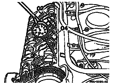
3. Install dial gauge, special tool (02) 363 589 02 2100 with threaded sleeve (04) at sealing surface of cylinder head cover at the camshaft to be tested.

4. Clamp dial gauge (01) with tracer pin (03) (80 mm) in the dial gauge holder (04) so that the tracer pin (03) is resting vertically on the bucket tappet (arrow) with a preload of 3 mm (small pointer of dial gauge).
NOTE: Check freedom of movement of tracer pin (03).
5. Turn scale of dial gauge until large pointer of gauge (01) is at -0-.
6. Rotate crankshaft in direction of rotation of engine with wrench socket, special tool 001 589 66 09 00 until the dial gauge indicates a valve lift of 2 mm.
In this position, the reading obtained at the vibration damper must agree with the reading "inlet valve opens ATDC" in table above.
Checking Timing Of Exhaust Camshafts

7. Rotate crankshaft in direction of rotation of engine until the lobes of the inlet cams to be tested are facing up (arrows) and only the base circles are resting against the bucket tappets.

8. Install dial gauge, special tool (02) 363 589 02 21 00 with threaded sleeve (04) at sealing surface of cylinder head cover at the camshaft to be tested.

9. Clamp dial gauge (01) with tracer pin (03) (80 mm) in the dial gauge holder (02) so that the tracer pin (03) is resting vertically on the bucket tappet (arrow) with a preload of 3 mm (small pointer of dial gauge).
NOTE:
- Check freedom of movement of tracer pin (03).
- Install tracer pin (03) at No. 6 cylinder on right of camshaft.
10. Turn scale of dial gauge until large pointer of gauge (01) is at a.
11. Use wrench bit, special tool 001589 65 09 00, to rotate crankshaft in direction of rotation of engine unfit dial gauge indicates a valve lift of 2 mm.
In this position. the reading obtained at the vibration damper must agree with the reading "exhaust valve closes BTDC" in table above.