• Hi Guest !

    Welcome to the 500Eboard forum.

    Since its founding in late 2008, 500Eboard has become the leading resource on the Internet for all things related to the Mercedes-Benz 500E and E500. In recent years, we have also expanded to include the 400E and E420 models, which are directly related to the 500E/E500.

    We invite you to browse and take advantage of the information and resources here on the site. If you find helpful information, please register for full membership, and you'll find even more resources available. Feel free to ask questions, and make liberal use of the "Search" function to find answers.

    We hope you will become an active contributor to the community!

    Sincerely,
    500Eboard Management

HOW-TO: M104 Top-End Rebuild (W463 G-Wagen G320)

gerryvz

Site Honcho
Staff member
I recently noticed that my 1995 G320 (M104.996 engine variant) was losing major coolant -- as in the expansion tank was going half-way down every time I drove the truck. Further investigation showed a major "drip-drip-drip" coolant leak at the back of the engine. Final investigation today is showing that there is a major coolant leak at the rear right corner of the head gasket. This is a common occurrence with the M104 engine, starting around 110-120K miles. The truck has around 133K on it.

So, this is going to necessitate the removal of the cylinder head, and essentially will lead to a total top-end refurbishment of the M104 in the truck. The last time I did this operation was in November, 2013 through January, 2014 on my ex-wife's 1995 E320 wagon, taking my time working in the garage. This operation was thoroughly documented here on the forum, in this thread.

This type of situation is EXACTLY why I opted to buy this G-wagen 10 years ago -- because of my familiarity with the M104 engine, and the fact that I had already done this one time and documented it both photographically, and in my hand-written notebook, step by step. Of course, things will be slightly different with the G-wagen, in terms of having a different setting in the vehicle (larger engine bay, no lower encapsulation and firewall panels, and so forth). I won't have to jack up the G-wagen to work UNDER the engine, because it is already high enough off the ground where I can easily get underneath it. The G-wagen's hood folds backward to rest on top of the windshield, so it will be completely out of the way.

A cursory check of key parts availability is showing pretty much all of the major parts I will need for refurbishment, to be available. This is going to be a comprehensive refirb, and will include not only the cylinder head being done, but the timing chain and tensioner being replaced, of course the front timing cover (which has been leaking for years) being replaced, cam adjuster solenoid being replaced, and much much more.

I haven't taken on a "big" job like this since my 2020 COVID engine bay refresh on my E500, so I am looking forward to digging into the job. I shall be commencing it this coming week. I will keep everyone informed along the way, photographically and descriptively in this thread. Because the G-wagen's variant of the M104 (the M104.996, as opposed to the E320's M104.992) is so similar to the W124's version, about 98-99% of everything will apply in terms of the mechanical work and dis/re-assembly of the engine. I have all of the needed special tools left over from my previous M104 job, and even some spare parts left over!! The previous E320 job took a bit over 60 hours, taking my time. I am expecting this one to likely take even more time, as I am planning to do a lot of "engine bay" refresh stuff as well.

So, stay tuned, as another big project saga is soon to commence!

Cheers,
Gerry
 
Hi Jerry,
Sounds like a hell of a project on your hands. I can't wait to read your blog and see how you do it.

I am already in my 3rd year of owning my G320, the first two years went pretty much trouble free but the beginning of this year my car failed its annual MOT/ (APK here in Holland). It failed on 4 issues.
No.1 - Perished Drag link and Tie bar track rod ends. Had to buy the entire Tie Rod bar as track rod ends no longer available and one end is fixed (what were Mercedes thinking!!). Damned expensive as well.

No. 2 - High CO reading, now the fun and games really began, replacing every sensor. Took the fuel rail off and tested and cleaned the injectors, new seals and clips. Also replaced the Fuel pressure regulator and a small in-line fuel filter in the rail. Interestingly, someone had left the old injector seals in the rail, so in there were 18 in total. Just yesterday I finally managed to get the O2 sensor off (I'd love to swear here but I won't), what a job. Anyone who tries to do this absolutely needs a set of rounded nut extractors and a MAP plumbers blow torch or welding gun. New sensor has a different connecting plug so I'm back at Mercedes on Monday to find out what to do (if anyone knows please advise, thanks).

No. 3 - Rear Brake Sensing valve leading to too much braking pressure at rear brakes. Another hell of a job trying to get the damn thing off, but I succeeded and even managed to find the replacement parts (no longer available at Mercedes). If anyone tries to do this you must get the car on ramps (I had to build a set of drive on ramps out of old pallets and patio stones so I could at least kneel under the car).

No. 4 - Final issue, no more than a lose wire on the front fog light.

However, since its off the road I decided to change the coolant (as well the Coolant sensors, 3 in total and the thermostat) and inspect and clean the underbody. All good fun!!

What I would say is that the guys in the Parts dept. at my local Mercedes garage have been absolutely brilliant. They print off the diagrams and part No. lists, even gave me a small discount on my last order and a Merc Hat and pen. Also some of the Mechanics came over and gave me some advice. I have read comments from other people on various forums where they have not had such a good service.

Finally for anyone looking for parts, try Kurth Classics Autoparts in Germany (great service), MBSpecialist International in Denmark (super helpful). Also for anyone who needs help with ECU issues, there is a great Company in the UK (although I don't have personal knowledge of that yet) ecutesting.com (great YouTube videos).

But all said and done, I can't wait to get the car back on the road.
Cheers and looking forward to reading your next article.
CHL
 
Looking forward to reading your posts on this Gerry. Do you have a heated garage? That would be max no fun doing this outside this time of year.
 
Any plans to build a shop / pole barn on your MD ranch, Gerry? Looked like you had plenty of space there!

200.gif
 
Looking forward to reading your posts on this Gerry. Do you have a heated garage? That would be max no fun doing this outside this time of year.
I have a heated garage, yes, thankfully. I wouldn't do this job outside, no way.

Any plans to build a shop / pole barn on your MD ranch, Gerry? Looked like you had plenty of space there!
We have a full acre, with a 1/2 acre out back. Originally I was going to build a shop out back, but we are not going to stay in this house for more than a few more years. The plan is to move south (likely coastal South Carolina or the Outer Banks) and build a new home to our spec, which will then allow the shop that I want. We were planning to go to Maine, but it's too cold and we want to live in an area with a longer boating season. So the coastal Carolinas it will be. @Trae-country..........

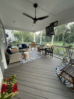
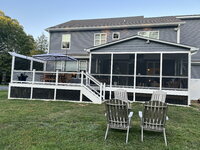
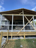
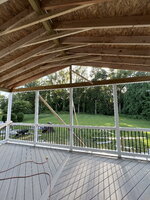
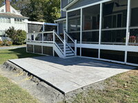
In summer/fall of 2022, we built this addition onto the back of our home....this is where our "shop money" went. It will do a better job of increasing the value of the house someday, when it comes time to sell. We're going to keep the house as a rental property for US Navy folks cycling through Annapolis for tours teaching at the Naval Academy (i.e. high quality renters). Debating whether a swimming pool is in order / next.

Unfortunately, from a political, crime and tax perspective (especially as a retiree), we can no longer stay in Maryland. So, our days are numbered here.
 

Attachments

  • IMG_3006.jpg
    IMG_3006.jpg
    1.6 MB · Views: 21
  • IMG_3004.jpg
    IMG_3004.jpg
    2 MB · Views: 17
  • IMG_3001.jpg
    IMG_3001.jpg
    2.1 MB · Views: 17
  • IMG_2698.jpg
    IMG_2698.jpg
    1.7 MB · Views: 16
  • IMG_2693.jpg
    IMG_2693.jpg
    1.6 MB · Views: 15
  • IMG_2691.jpg
    IMG_2691.jpg
    1.9 MB · Views: 18
  • IMG_2690.jpg
    IMG_2690.jpg
    1.5 MB · Views: 16
  • IMG_2688.jpg
    IMG_2688.jpg
    2.1 MB · Views: 18
  • 68756112908__F17D47AC-B6CF-4D00-B823-F434E209D101.jpg
    68756112908__F17D47AC-B6CF-4D00-B823-F434E209D101.jpg
    2.8 MB · Views: 18
  • IMG_7488.jpg
    IMG_7488.jpg
    2.4 MB · Views: 17
  • IMG_7343.JPG
    IMG_7343.JPG
    3 MB · Views: 16
  • IMG_7341.JPG
    IMG_7341.JPG
    3.5 MB · Views: 15
  • IMG_7339.JPG
    IMG_7339.JPG
    3.1 MB · Views: 16
  • IMG_7212.JPG
    IMG_7212.JPG
    2.6 MB · Views: 17
  • IMG_7208.JPG
    IMG_7208.JPG
    3.9 MB · Views: 20
I am fortunate to have found an excellent machine shop locally that will refurbish the M104 cylinder head when I pull it. For anyone in the Baltimore area, this machine shop is:

Ellison's Machine Shop
7218 Ritchie Hwy #3039
Glen Burnie, MD 21061
(410) 766-6763

Ken Ellison, owner

He's been in business for 40+ years.
 
Tonight started the long-awaited beginning of my Top-End Rebuild for my G-wagen's M104 engine. With approximately 135,000 miles on the engine, the head gasket has finally given out, and is severely leaking coolant from the rear passenger corner of the cylinder head. This is about right on schedule for an M104 with the original design cylinder head gasket, which usually fails between 120,000 and 150,000 miles.

The current design of the Mercedes M104 cylinder head gasket, which has been revised probably 3-4 times over the years, has now been perfected, and very rarely if ever fails.

The situation with my cylinder head gasket failure was likely exacerbated by the hot running of the G-wagen's M104 engine for approximately 18 months, usually between 105 and 115C indicated, because of a bad thermostat. After remedying this situation, the G-wagen has run for several years very cool and with no problems; however the elevated temperatures run for an extended period of time likely accelerated the failure of the head gasket.

In any case, this is the opportunity to do a complete engine bay and Top-End Refresh operation, similar that I did back in 2014 with my former E320 wagon with an almost identical engine.

I got started on Sunday by backing the G-wagen into the shop, and raising the hood up and backward into the "service" position, where it folds back against the windshield. I used a heavy moving blanket draped on the roof and windshield to cushion the hood so that it does not damage anything, as you can see below.
IMG_1180.jpeg


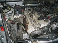
Here is an overview of the G320's M104 engine as it sat at the beginning of the project.
IMG_1181.jpeg


The first step I did, was to disconnect, and then remove the battery from the engine compartment. The battery was last replaced in XXX, 20XX, so it is likely that I will replace the battery at the end of the project. I will charge it and test it with a battery health tester to see if it is in usable condition, though.
IMG_1182.jpeg IMG_1183.jpeg


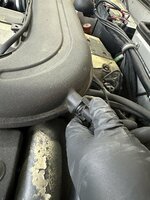
Next up was to remove the MAF connector from the upper wiring harness.
IMG_1184.jpeg IMG_1185.jpeg


Then I un-clipped the two clips holding the MAF to the intake zoom tube coming out of the air filter housing, as shown. Then I removed the intake air temperature sensor. I will replace this sensor when I re-assemble everything.
IMG_1186.jpeg IMG_1187.jpeg IMG_1188.jpeg


The next step was to remove the intake air crossover tube from the engine. There are three nuts that hold the tube to the top of the cylinder head cover, which need to be removed. Here I am lifting the air crossover tube off of the engine, after working it out of the rubber boot that sits atop the ETA.
IMG_1189.jpeg


Remove the front black plastic cylinder head cover, taking care not to break any of the slots that hold it to the front of the engine.
IMG_1190.jpeg


From there, use a 5mm Allen socket, and remove the six long bolts that hold the black plastic piece covering the coil packs, plug boots and plug wires on top of the cylinder head cover. It should just lift off after the bolts are removed.
IMG_1191.jpeg IMG_1192.jpeg


The next thing I did was to remove the top of the air filter housing. I then removed the air filter, which it shows I had last replaced in September 2014, not long after I acquired the G-wagen. This is a special air filter with metal reinforcement and a foam piece on the bottom, that is specifically for the G320 models. I have a new spare unit that I will replace this with when I reassemble things, seeing as it is 10 years old and has gone approximately 40,000 miles -- probably about double the service life I should have let it go.
IMG_1193.jpeg IMG_1194.jpeg IMG_1195.jpeg IMG_1196.jpeg


Next, I removed the two 10mm bolts that held the air filter housing bottom half to the engine compartment. One of the plastic flanges that mounted the housing to the truck's inner fender had broken off -- not a fatal condition, but I will see if this piece is still available from MB. If not, I will just re-use it with no problems.
IMG_1197.jpeg IMG_1198.jpeg


Here is the routing of a vacuum line from the front vacuum switchover valve to the EGR valve on the rear exhaust manifold. This is mainly a pair of reference photos. The vacuum line broke quite easily, so it (like all vacuum lines underhood) will be replaced upon reassembly.
IMG_1199.jpeg IMG_1200.jpeg


Next, I lifted off the black plastic cover over the upper wiring harness -- mainly the fuel injector connectors and fuel rail.
IMG_1201.jpeg


TO BE CONTINUED SHORTLY
 
Last edited:
This will no doubt be another epic HOW-TO that I’m looking forward to following. Gerry, I may have asked you this a month or two ago but now that you have started the work I’m sure you’ve already started a parts list and are currently sourcing parts. How many parts are NLA from the dealer and have you decided how you will handle this? If there is no “reputable” part manufacturer for a part, would you install new Chinesium, used factory or try to repair the worn or broken part? No doubt so many of the parts you used on your M119 top-end resto are NLA and I’m thinking you are bound to run into this at some point on the M104, even with your massive parts stash.
 
Here is a view of the engine with the top covers removed.
IMG_1931.JPG


The next step is to begin removing the various connectors at the end of the upper wiring harness. I am 99% sure (and was at the time I purchased the G320 in 2014) that the upper harness had been replaced with a non-biodegradable harness, so the wires and connectors are in good condition.

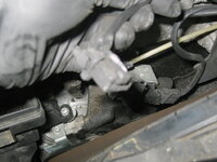
Here is the cam position sensor connector being removed, on the front of the cylinder head.
IMG_1932.JPG


Next was the cam adjuster magnet connector.
IMG_1933.JPG


From there, I decided to begin removing the vacuum switchover valve on the front of the head cover, under the black plastic engine cover when installed. Two vacuum lines connect to this valve, as well as an electrical connector from the upper wiring harness. Both vacuum valves were very brittle, so I just manually and "on purpose" snapped them off, as I will be replacing them. One vacuum line leads under the black plastic top cover and goes to the EGR valve on the exhaust manifold, and the other one snakes along the front of the engine and goes to the intake manifold.

Here you can see the vacuum valve with one of the vacuum lines removed. It is held onto the front of the engine with two 10mm bolts, which are very difficult to access due to the design of the vacuum switchover valve housing. It took me a bit of time to wrestle with them, but I eventually removed them. The second photo shows a non-used connector that has been taped off. Evidently this is something that is specific to my model of the G-Wagen.
IMG_1934.JPG IMG_1935.JPG


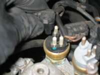
From there I proceeded with removing the electrical connectors at the engine temp sensors, located on the thermostat flange.
IMG_1937.JPG IMG_1938.JPG IMG_1939.JPG IMG_1940.JPG


And then I removed the six fuel injector electrical connectors atop the engine. To do this, you just squeeze the two metal wire edges on each connector together, and lift upward. The second and third photos show a non-used electrical connector, again for my model of the G-wagen.
IMG_1941.JPG IMG_1942.JPG IMG_1948.JPG


The upper wiring harness, when it was replaced, was zip-tied at two points directly to the fuel rail. Using a pair of small wire-cutter pliers, I snipped both of the zip ties to release the harness from the fuel rail.
IMG_1943.JPG IMG_1944.JPG IMG_1945.JPG IMG_1946.JPG


Next, it was time to begin removing the ignition apparatus. I unplugged the spark plug wire connectors from all of the three coil packs, and removed the ignition wire assembly.
IMG_1949.JPG IMG_1950.JPG


Then I lifted off the thin black cover on the inside of the valve cover. This thin black plastic piece covers part of the ignition wires, and just presses into place (and lifts off, for removal).
IMG_1951.JPG


Removing the ignition wires and the three spark plug boots, by directly lifting upward.
IMG_1952.JPG IMG_1953.JPG IMG_1954.JPG IMG_1955.JPG IMG_1956.JPG


After doing that, it was time to remove the three coil packs. Again, these just lift upward, though the spark plug boots on the bottom of each one give you a little resistance.
IMG_1957.JPG IMG_1958.JPG


Here's what the top of the valve cover looks like with all of the ignition components removed.
IMG_1959.JPG


Next up, I removed the red rubber vacuum connector from the EGR valve on the rear-most exhaust manifold.
IMG_1960.JPG


And then I took a look at the battery box. It looked in pretty decent condition, with just a tiny smidge of surface rust. I will probably coat that with black sealing paint to head off the rust, as it won't be visible with the battery in place. All in all, in good condition for a 30-year-old truck.
IMG_1961.JPG


Next up, I continued to remove the lower part of the air filter box. It connects with two 10mm nuts up top, and presses into a rubber bushing located on the inner fender on the bottom. As you can see in the second photo, one of the two flanges that hold it in place was broken off. In the third photo, you can see the rubber bushing that it presses into.
IMG_1962.JPG IMG_1963.JPG IMG_1964.JPG


I finally finished removing the vacuum switchover valve. Access its two 10mm nuts was a real PITA, and took me a good 15 minutes to find a workaround so I could get a good "bite" on them with a wrench. I also sprayed them both with Kroil to help loosen them a bit.
IMG_1965.JPG IMG_1966.JPG IMG_1967.JPG


That last thing I did, before buttoning up for the night, was th remove the upper wiring harness connector located under a couple of the radiator hoses on the driver's side of the engine.
IMG_1968.JPG IMG_1969.JPG


There is only one connector left to remove from the engine, before I can remove the upper wiring harness from the truck. This is the knock sensor connector, which is located on the engine block, on the driver's side. I will have to access this from underneath the truck, as it's impossible to reach from above with the intake manifold in place. To get to this, I'm going to have to remove the heavy metal skid plate that is mounted underneath the front of the engine. But, that is a job for the next session.
 
This will no doubt be another epic HOW-TO that I’m looking forward to following. Gerry, I may have asked you this a month or two ago but now that you have started the work I’m sure you’ve already started a parts list and are currently sourcing parts. How many parts are NLA from the dealer and have you decided how you will handle this? If there is no “reputable” part manufacturer for a part, would you install new Chinesium, used factory or try to repair the worn or broken part? No doubt so many of the parts you used on your M119 top-end resto are NLA and I’m thinking you are bound to run into this at some point on the M104, even with your massive parts stash.
I am not far enough into the job, yet, to be able to answer this. Yes, I have begun compiling a list of parts to acquire (as well as some it would be nice to replace). So, I will have an update on this as I go along, at various points.

Some of the part, such as the three coil packs, I am planning to just replace with new parts. I had replaced one coil pack about 3-4 years ago after it failed, with a new Bosch part, which was made in Slovenia. The other two coil packs are original Bosch that were made in Germany. I am planning to replace a lot of stuff - some of which won't techncially be needed to replace.

That said, I will definitely keep a running tab as to what is and isn't available. I will NOT install anything Chinese or cheap on this engine, and rather will go used or quality aftermarket instead. Being an M104, with a LOT of these engines being made and still on the road, I believe the parts availability situation may be a little bit better than for the M119, but we shall see. I didn't have any problems getting stuff in 2014 when I did the E320 M104, but now that 10 years have passed by, the NLA situation may be worse.
 
This will no doubt be another epic HOW-TO that I’m looking forward to following. Gerry, I may have asked you this a month or two ago but now that you have started the work I’m sure you’ve already started a parts list and are currently sourcing parts. How many parts are NLA from the dealer and have you decided how you will handle this? If there is no “reputable” part manufacturer for a part, would you install new Chinesium, used factory or try to repair the worn or broken part? No doubt so many of the parts you used on your M119 top-end resto are NLA and I’m thinking you are bound to run into this at some point on the M104, even with your massive parts stash.
Very early on, I am finding that all of the key gaskets and soft parts are generally available -- so far. I have checked all of the critical intake system soft components, including o-rings, intake and exhaust manifold gaskets, copper exhaust manifold nuts, vacuum switchover valve, and so forth -- everything is available.

The air filter box is NLA from MB, so I will have to re-use mine. Perhaps I can use some JB Weld or other cement to effect a repair on the airbox, to re-attach the mounting flange. If not, it's not a big deal, it will still work just fine as is.

The air filter itself is NLA, which I have known for probably 5 years. HOWEVER, it is the same size shape as the standard E320 air filter, and that unit can be substituted. However, I will use the remaining metal-reinforced, G-wagen specific air filter that I have in my parts stock when it comes time to replace it.

I am probably going to go ahead and replace the A/C compressor, as I believe it has been leaking and is causing the refrigerant to leak out. Which is too bad, as I had it replaced about 7 years ago along with the receiver-drier, evap and other components to get the A/C working, which it did for several years. The A/C compressor is very accessible now given that the air intake box is out - it is just below it.
 
I am probably going to go ahead and replace the A/C compressor, as I believe it has been leaking and is causing the refrigerant to leak out. Which is too bad, as I had it replaced about 7 years ago along with the receiver-drier, evap and other components to get the A/C working, which it did for several years. The A/C compressor is very accessible now given that the air intake box is out - it is just below it.
Gerry, are you certain the compressor is the root cause of the refrigerant leak? Is there evidence of oil leaking from the front shaft seal, or other symptoms that the compressor is suspect?

:klink:
 
Gerry, are you certain the compressor is the root cause of the refrigerant leak? Is there evidence of oil leaking from the front shaft seal, or other symptoms that the compressor is suspect?

:klink:
I haven't fully investigated it yet, so can't say for sure. I'll know more when I have the time to really look at it from above and below. It does look tight at the manifold on the top side on the compressor. No obvious leakage there.

Separately, I have pretty much looked into every part that would be replaced on the engine. The only major part that is NLA from MB is the ETA gasket, but this is availble from AutohauZ as an Elring part for $2.19.

All other key gaskets are available either as MB or Elring parts (and MB specifies Elring as the head gasket OEM in the EPC).

The chain tensioner, which I will plan to replace, is available as an INA part from the aftermarket for about 1/3 the price of the MB part (which I suspect is also made by INA). I need to look to see if INA is on the naughty or nice list, but I seem to remember them being an OEM for MB for these parts. Anyone know for sure?

This is going to be an expensive rebuild. I'm hoping the cylinder head is in good condition and not warped or otherwise damaged. Haven't had any problems with it at all, and drove on it for 3-4 years before it started leaking coolant.

:update:

The camshaft position sensor, MB part number 002 153 95 28, which is used for the early models, is NLA from MB, but is available aftermarket as a Hella part. The later cam position sensor (not used on my G-wagen, but used on many other M104 models (there is an engine number break-point), which is MB part number 004 153 00 28, is still available from MB for ~$130, discounted.
 
Last edited:
Gerry don’t forget about the set of NOS MB factory G wagon fender covers I sent you a couple years ago!

Perfect for this project

🍻
Damn, I did. I’ll go down to the basement and get them tomorrow. Tonight I worked under the G-wagen mostly, removing skid plate and draining radiator. And cracking open the block drain.

But the vast majority of this work will be up top, so those fender covers will be super helpful. Thank you for the reminder !!
 
The second night of disassembly operations, I only worked in the shop for an hour. Continued with basic preparation for the job, mostly with tasks under the truck.

First of all, after the first night's beginning of disassembly, here is how the engine compartment looks, as an overview.
IMG_1970.JPG


The next task was to drain the coolant from both the radiator and the engine block. Given that the Nissens radiator (which I replaced the original Behr radiator with about 5 years ago) doesn't have a lower corner pet-cock to drain coolant, it fell upon me to drain the radiator's coolant via the lower radiator hose.

To get at the lower radiator hose, I needed to remove the lower metal skid-plate from under the engine. This was a relatively simple operation, consisting of removing a total of six 17mm nut/bolt combos that held the quite-heavy skid plate to the frame of the vehicle. This operation only required a 17mm socket and a 17mm open-end wrench to counter-hold the nuts atop the plate's mounting brackets. The photos below show the beginning of loosening the plate, and then carefully dropping it down onto the ground.
IMG_1971.JPG IMG_1972.JPG

The plate is not in bad condition, but it is likely that I will have it cleaned, blasted and then powder coated as part of the refurbishment procedure.

Here is a view of the engine oilpan. You can see that it is encrusted with oil and dirt, most likely from the (very common) oil leak at the M104's front timing cover, seeping downward. Not the worst I've ever seen on an M104, but bad enough.
IMG_1973.JPG


I also decided at this point in time that I will remove the hub and pulley, and likely replace the front crankshaft seal as well. Sort of a "while you're in there" type of operation, and not that much more labor to be honest. This will be the first time I will have replaced a FRONT crank seal on an M104. I have done the REAR crank seal, and the FRONT crank seal on an M119, but not on the M104.

The next operation was to locate and then do a quick check to see whether I could loosen the engine's crankcase drain. Unlike the V-8 models, the M104 only has a single block drain. Fortunately with my vintage of the M104, a later one, it has the "revised" drain that you can attach a hose to, turn, and it will drain downward through the hose, making things fairly neat.

Here is the drain on the passenger side of the engine block.
IMG_1975.JPG


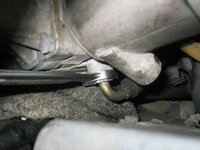
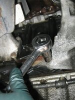
Putting a 19mm box-end wrench onto the drain plug, and turning it counter-clockwise about a third to half a turn (with GREAT effort to break it loose), I started getting drops of coolant through the plug. Satisfied that I could turn it and drain the block, I turned it clockwise again to tighten it, and will drain it after locate an appropriate length of hose in the shop with a 14mm inside diameter to fit the plug.
IMG_1976.JPG


Next up was draining the radiator. As mentioned there is no radiator drain, so I loosened the clamp on the lower radiator hose (which is likely original, and I will look to replace if available). Coolant cascaded outward and downward into the drain pan and all over the cardboard it was sitting on after I loosened it. I even got a tiny bit of coolant in my open mouth -- and man it DOESN'T taste good :(
IMG_1978.JPG IMG_1977.JPG


After the radiator had drained into my pan, I removed the two clamps for the upper radiator hose from the thermostat housing to the radiator. No coolant leakage, as everything had already drained.
IMG_1979.JPG IMG_1980.JPG IMG_1981.JPG IMG_1982.JPG IMG_1983.JPG


Last task of the night was to begin to remove the two clamps that hold the wiring and vacuum line bundle to the front of the fresh cabin air intake. I found that the 10mm nuts needed to be counter-held from inside the fresh air compartment, and the flap was closed. So, I will need to temporarily connect a battery to open the flap, so I can get in behind the nuts to hold the bolt-heads. Easy enough, and I'll get to it soon.
IMG_1984.JPG


That was all for the second night.
 
I am fortunate to have found an excellent machine shop locally that will refurbish the M104 cylinder head when I pull it. For anyone in the Baltimore area, this machine shop is:

Ellison's Machine Shop
7218 Ritchie Hwy #3039
Glen Burnie, MD 21061
(410) 766-6763

Ken Ellison, owner

He's been in business for 40+ years.
Hi Gerry,
Thanks for the information, did you have any bad experience while your' driving your G320?
I was driving back to home, and my 1995 G320 suddenly stops. I try to start it but the starter motor only makes noises trying to turn it on but it doesn't work. I leave it for 10 minutes and it starts. What causes this problem?
Thanks for any advice.
Best,
Fernando Leiva
Oxon Hill, MD
 
After a very long hiatus from this project, mainly because of cold winter weather, I am happy to report that I have restarted this project over this weekend, and put my first four-hour work session in. Made some decent headway, and took a fair number of pictures.

First update will be posted soon, with more to come. I’ll be working going forward to see this project through to the end.

One observation is that in taking the valve cover off today, I (as I sort of expected) found that someone had removed it in the past, as there was RTV all over the place. Looks like the valve cover was removed and replaced, along with the front timing chain cover. Common issue with the M103 and M104, and whoever did the work slapped RTV all over.

So, I will have to scrape all that off.

The good news is that the engine is super-clean under the valve cover, and the cam lobes are in excellent shape. I have put over 40,000 miles on the G-wagon since buying it in 2014.

Soaked the top row of the exhaust manifold bolts in Kroil, and test-loosened a bunch of them. They loosened right up, fortunately.

I also test-loosened a camshaft cap bolt (Torx) and it loosened right up, which means I will be able to remove both cams. I was not able to do this with the previous M104 I had because all cam cap bolts were UBER-tight — the machine shop in Houston I used had to weld a nut to some of the cam cap bolts in order to loosen them. The torque spec is only 21 Nm for these bolts, which honestly is not all that much.

Looking forward to getting back into this project.

More very soon!
 
As I’m preparing my first parts order for this coming week, everything that I have found, including two G-wagen-specific large coolant hoses going from the engine to the water pump & thermostat housing, is (so far) totally available.

That’s encouraging…..
 
So, after many months of inaction, I finally decided to clear out the garage around the G-wagen and get started again on the stalled M104 cylinder head project, because the weather has gotten better, and I could really use the garage space for another one of my cars. So, on Sunday early afternoon I re-initiated the project, and spent a solid four hours out in the shop, getting re-started on the project.

The first thing I did was to put a drain pan under the side of the M104 engine block, and loosen the block coolant drain plug to begin the flow of coolant out of the block. I attached a hose to the drain plug to help direct coolant downward into the pan, and then just left it to let it do its thing.


Next, I decided to remove the valve cover, to take a look at the condition of the cams and top of the cylinder head. In 11 years and 40,000 miles, I actually had NEVER had the cam cover off of the top of the engine! So, I loosened and then began to remove all of the 12 bolts that held the cam cover to the head. I will need to replace each of the 12 rubber inserts on the bolts, which prevent oil leaks out past the bolt holes.
IMG_2004.JPG IMG_2003.JPG


The next step was to remove the vertical sheet-metal "heat shield" that goes between the exhaust manifolds and the front suspension and air intake/filter box, on the passenger side of the engine. This was held onto the frame and to a bracket by three of four bolts, and just lifted right out.
IMG_1988.JPG IMG_1986.JPG IMG_1985.JPG IMG_1987.JPG


Next up....removing the serpentine belt. That was easy enough, just loosen the belt tensioner and then slip the belt off of the pulleys.
IMG_1989.JPG


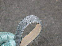
Once removed, this was what I found the condition of the serpentine belt to be in. It was time for replacement......
IMG_1991.JPG


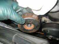
Checking the condition of the belt tensioner pulley, it was slighly wobbly and made a bit of noise at the bearings, so I removed it. This is what I found -- it was functional, but honestly needed replacement. The original style INA pulleys are available, or a revised-up MB design. I opted to put the MB design (made in Germany) on my first parts order.
IMG_1992.JPG IMG_1993.JPG IMG_1994.JPG


To make more room around the lower front portion of the engine, it was then time to begin removing accessories. First up for this is the A/C compressor. The compressor is held to its bracket with just four long bolts, which I removed, after unplugging the compressor's electrical connection. After unbolting the compressor (it is still attached - for now - by the manifold with the two A/C lines), I set it down and aside. I will fully remove it shortly.
IMG_1995.JPG IMG_1996.JPG IMG_1997.JPG


From there, I removed the cam position sensor on the end of the cylinder head. Easy enough -- two Allen bolts.
IMG_1998.JPG IMG_1999.JPG IMG_2000.JPG


After that, I finished removing all of the 12 bolts from the valve cover. Began lifting the cover off the top of the cylinder head.
IMG_2001.JPG IMG_2002.JPG IMG_2005.JPG IMG_2006.JPG


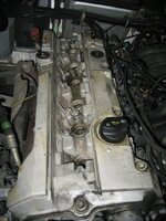
And here is a good view of the cylinder head, cams, and such. Looks pretty clean. Mostly because I use the 15W-40 Chevron DELO 400 Diesel oil, which has great detergents in it that keep things nice and clean.
IMG_2007.JPG IMG_2008.JPG


Here's a close-up of the cams and caps.
IMG_2009.JPG


Aaaaaaannnnnnndddddd....I found just what I DIDN'T want to find .... some jerk had been in there before me, and used RTV all over the place to seal the valve cover. UGH. SIGH. SHIT. FUDGE.
IMG_2010.JPG IMG_2011.JPG


Well, I'll deal with that crap down the road. Getting back to work, next thing was to remove the cam solenoid. Again, three Allen bolts, as typical. Date code shows it's the original unit, with the 104 part number. I'm going to replace it with a factory fresh Pierburg unit from MB, on my parts list. Matching armature too, along with a new one-time-use armature bolt.
IMG_2012.JPG IMG_2013.JPG


And as the solenoid comes off, you can see the dried up orangle koala-claw anaerobic sealant, which did its job for 31 years. But, it's time for a new solenoid and new orange goo in the near future.
IMG_2014.JPG IMG_2015.JPG


Here are a couple of close-ups of the solenoid on the bench. Note the date code.
IMG_2016.JPG IMG_2017.JPG


Next job was to remove the clips from the fuel injectors, that keep them attached to the fuel rail. Easy enough to pop them off with a flat-blade screwdriver.
IMG_2018.JPG IMG_2019.JPG IMG_2020.JPG


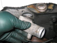
And then, the thermostat housing atop the water pump. Three bolts and it was off.
IMG_2021.JPG IMG_2022.JPG IMG_2023.JPG IMG_2024.JPG


Thermostat is a Wahler, just a few years old, but I'll replace it with a fresh Wahler unit (no more Behr units for me!) when I button everything back together.
IMG_2025.JPG


Then I removed the two bolts that held the front lifting lug to the cylinder head.
IMG_2027.JPG IMG_2026.JPG


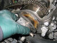
And with all of this removed, it gave me a nice view of the vaunted "Bermuda Triangle" -- that unique area on M103s and M104s where the front timing cover meets the cylinder head and the top of the engine block. As you can clearly see, it is HEAVILY coated with oil and dirt, meaning there has been a pretty nasty leak there for some time now. I am sure that this cover was re-sealed previously (undoubtedly using RTV), and this is why the valve cover was also removed and re-sealed with RTV. It will be satisfying to clean this area up.
IMG_2028.JPG IMG_2029.JPG


After exposing the Bermuda Triangle area, I removed the fuel lines from the fuel rail, and capped them off with brass plugs I have, just for that exact purpose. BOTH fuel lines are in nice condition, and don't appear to need replacement. It appears that they may have been replaced in the past, perhaps.
IMG_2030.JPG IMG_2031.JPG


And before knocking off, the last thing I did was do a few "test" loosenings of a few select exhaust manifold copper nuts. I had previously soaked most of them in Kroil for a few hours, so they were ready to go. I'm happy to say that all of the nuts loosened up just fine. And, I put 23 new copper nuts on my parts order.
IMG_2032.JPG

I did the same by test-loosening one of the cam cap bolts, and it loosened right up. So, it will be nice to be able to remove the cams before taking the cylinder heads into the machine shop for a proper refurbishment.

That's all for this installment. More to come soon......
 
Thanks for kicking this off again, I need to do this as things have slowly started to wear to the point of R&R on my M104 (1994 124.092).

What valve covers for the M104 are interchangeable, if any? I'm looking for a replacement as mine has progressed on it's paint chipping and the spark plug cover is starting to warp. But unlike yours, mine is also magnesium and I notice on certain years they are plastic and run the full length of the valve cover. I've even found that a select few W140s that had the M104 had aluminum covers but I can't find validation if these will fit or even compatible - in the rare case one is located.
The valve cover you mention with the long black plastic strip in the middle that says "MERCEDES-BENZ" is a CIS M104, used on the 124 (mostly coupes and cabrios) for a couple or three years, and you will always see a "300CE-24" on the trunk. Don't bother with these. You want a valve cover from a 1993-1995 E320 on the W124, or perhaps a 1996 or 1997 E320 in the W210.

That said, any 104.99x valve cover (HFM cars) should be interchangeable. The valve covers for the earlier CIS cars (104.98x) are not the same as the HFM cars. I am not sure about the LH-injected M104 engines, but they (as far as I know) were only used for a year or two in the US, and only in the W140 models? Basically any M104 in the US (post-1992) is going to be an HFM car.

I am going to get my valve cover totally sand-blasted and the old paint removed, and new powder coating applied. Haven't decided whether to go with a red (did this before), or blue, or just mimic the factory color.
 
I should have probably outlined this at the beginning of the thread, but this is going to be the scope of the work for this project, as I’ve identified it in the early stages. Of course, there will be some scope creep (there always is with my projects), but at this point, this is what I see myself doing.

A lot of these parts are working fine, but am replacing them out of hand per my personal philosophy.
  1. Removing and refurbishing cylinder head at a local machine shop
  2. Blasting and re-painting magnesium valve cover (color is TBD)
  3. Replacing front crankshaft seal (a “while in there” job; may as well)
  4. Replacing most all soft parts under hood (hoses, vacuum lines, intake parts, gaskets, etc.)
  5. Replacing thermostat (still fine, but may as well refresh with a new one)
  6. Replacing “MOT” fuel vapor valve
  7. Replacing upper and cylinder head timing chain guide rails
  8. Replacing timing chain tensioner
  9. Replacing cam solenoid and armature with new units
  10. Replacing A/C compressor
  11. Replacing all valve cover, exhaust manifold and intake system gaskets
  12. Replacing all radiator hoses (upper and lower)
  13. Considering replacing water pump (I have a new Graf unit for the G-Wagen)
  14. Considering replacing entire exhaust system (existing system is worn out and needs cats)
The under hood area is very dirty, so I will be cleaning things up as well.

The upper wiring harness has been replaced (before my ownership), and the ETA has also been replaced with a later unit (I got a glimpse of the date code on it, although I have not yet removed it). I have not inspected the lower wiring harness, and don’t know if it is still available or not.

My first major parts order should be in tomorrow, or Friday at the latest. Interestingly, all of the parts i ordered (and there were quite a few on this first order) were in the US — nothing had to come from Germany.
 
I have a couple of tubes, including a new tube. The open tube I have is from my COVID 2020 E500 Engine Bay Refresh. It may still be OK. I’ll have to check my open tube of the clear stuff.
As a bit of a "sidebar," I took an inventory of my MB sealants, and this is what I found:

An opened tube of black RTV sealant, MB part number 003 989 98 20 10. Date code is September, 2013. This sealant IS STILL AVAILABLE FROM MB, for a price of around $25-30 from normal discount online MB parts dealers.
IMG_2617.jpeg IMG_2618.jpeg IMG_2619.jpeg


An opened tube of orange koala-claw + satsuma goo, part number 001 989 89 20 10. Date code for expiration is 01/2021. I used this in my 2020 COVID engine bay refresh of my E500, for the front cover and cam solenoid sealing. I will likely use this orange goo for this M104 job, as well. This goo is NLA from MB.

IMG_2620.jpeg IMG_2621.jpeg IMG_2622.jpeg IMG_2623.jpeg


An unopened tube of orange koala-claw + satsuma anaerobic goo, which I received from Clark Vader back in 2016. This is also same, part number 001 989 89 20 10, and has an expiration date of February, 2016.
IMG_2624.jpeg IMG_2625.jpeg IMG_2626.jpeg IMG_2627.jpeg IMG_2628.jpeg


A THIRD tube of orange koala-claw + satsuma anaerobic goo, MB part number 001 989 89 20 10. This is an opened tube that I purchased in 2013 for the M104 Top-End Rebuild of the former @gsxr / @Dbreid / @Jouser "StigWagen" 1995 E320. I had notated in marker, on the box, at the time that "This supersedes MB 002 989 47 20 10 and is Omnifit FD 3041 or Loctite 574.
IMG_2629.jpeg IMG_2632.jpeg IMG_2633.jpeg


An opened tube of 002 989 45 20 RTV sealant, with expiry date of 06-02-2013. This is the clear sealant that is used in one "glob" or "dollop" (or a "button" as MB says in the work instructions) at each of the corners of the "C" shaped timing cover seal, at the "Bermuda Triangle" area where the cylinder head, block and timing cover meet....the notorious M103 & M104 oil leak spot. This sealant is also NLA from MB, and I will use it for this job.
IMG_2634.jpeg IMG_2635.jpeg IMG_2637.jpeg IMG_2638.jpeg


If anyone wants to purchase the NLA tube of NOS / unopened orange koala-claw+satsuma goo, per above, my price is EUR 6,250. You can get the Elring equivalent, new, for about $25-20 USD. But for those wanting NOS goo, I am happy to sell it.
 
Last edited:
FYI - the black RTV stuff 003-989-98-20-10 (allegedly similar/same as Loctite 5970) has an increasingly long time to cure once expired. Allegedly fresh stuff cures within 24 hours.

I had a tube of this which was a few years expired, and I used it on a differential cover once. The diff was on the workbench and I wasn't in a rush. It took over THREE WEEKS for the expired stuff to cure!! But, it did cure ok and did not leak when installed. Keep this in mind if you use that goo.

I've been using Permatex Right Stuff in the pressurized can since then for most RTV needs. I think the canned goo may last longer. Maybe.

:scratchchin:
 
That's good info on the black RTV. It's common enough that I should probably just throw the old stuff out.

I can't remember what I used it for, but I think maybe it was for the previous M104 job I did. I'll have to look back at the HOW-TO I did and see where I had used it.

Interestingly, with nearly 144,500 views of this thread at the present time, that M104 / W124 HOW-TO is one of the most-read threads on this forum. Seems like it is a very in-demand thread, especially for non-V-8 folks who are doing an E320 or W140/R129/W202 M104, etc. Also seems that the M104 / W124 thread appears quite high in Google search rankings on the topic.

Screenshot 2025-04-10 at 5.02.27 PM.png
 
Today I spent about 5.5 hours out in the shop, working on a variety of disassembly tasks on the M104. Made some solid progress, although there is still a TON to do, even before I get to removing the cylinder head.

First thing I did was to remove the thermostat. It's only about 4 years old, but it's a cheap part, and I have a new Wahler unit on order (also I have a couple of Behr units in my parts stock, but I don't trust Mahle Behr thermostats anymore). Wahler is owned by Borg-Warner now, so if you see Borg-Warner thermostats for the M104 application (different than the M117 and M119), it will be a Wahler unit in the box, made in Germany.
IMG_2033.JPG


Next thing was to finish removing the A/C compressor. I had to remove the manifold from the top of the compressor using a special, long, 6mm Allen socket. It came off with some effort, and then I removed the compressor from the truck. It was a new one in 2017, but I have decided to replace it with a new unit, since it is literally an off-the-shelf Denso compressor that is also used in the US-market E320 and many other vehicles. I think they are like $150 new, so why not?
IMG_2034.JPG IMG_2035.JPG IMG_2036.JPG


After removing the compressor, I zip-tied the manifold and hoses to the side of the engine compartment, to keep them out of the way.
IMG_2037.JPG


For the next item, I continued working on removing all of the bolts that held the fuel rail and the intake manifold to the cylinder head, on the driver's side of the engine. I did get all of the bolts out, except one -- the very rear-most and lowest one, in which I stripped out the head of the 6mm Allen. Its position next to the oil filter housing makes getting to this bolt very difficult. I'm going to have to figure something out. Here are a few photos of the bolts being removed, as well as a blurry photo (for my later reference) of the engine ground to the rear of the engine compartment.
IMG_2038.JPG IMG_2039.JPG IMG_2040.JPG


Quickly removed the vacuum line from the fuel pressure regulator, and tucked the vacuum line out of the way.
IMG_2041.JPG


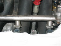
This is a photo of the fuel rail. It's almost ready to come out (together with the fuel injectors) once I get that final bolt removed from the back end of it.
IMG_2042.JPG


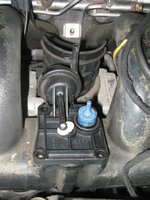
The next thing I removed was the resonator valve, from the center of the intake manifold. Four bolts hold it on. One less job to do when I remove and disassemble the intake manifold....
IMG_2043.JPG IMG_2044.JPG IMG_2045.JPG IMG_2046.JPG IMG_2047.JPG IMG_2048.JPG IMG_2050.JPG


This is the underside of the resonator valve. I unplugged the electrical connector from the wiring harness.
IMG_2049.JPG


From there, I removed the upper coolant hose connector that presses into the front timing cover. Some total dode was in there before me, and unfortunately RTV'd that connector to the cover. I was able to wiggle it free with not too much problem, though. More to clean up after I begin re-assembly of the top end....sigh.
IMG_2052.JPG IMG_2053.JPG


After that, I removed the two coolant temperature sensors that screw into the top of the water pump housing. Used a large Crescent wrench to loosen them, and they came out easy enough. I'll likely replace them with new units when I begin re-assembly.
IMG_2051.JPG


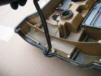
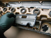
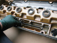
Decided to shift gears after all of this, as I needed a different mental focus. So, I grabbed the valve cover, and decided to remove the two baffle plates and plastic inserts that screw into the underside of the cover. This will help prepare the cover for blasting and powder coating, which I will probably take it into the shop this week to do. Still haven't decided what color to paint the valve cover.

Again, the same dode used RTV on the valve cover gasket (the groove portion). I hate these idiots who do this.
IMG_2057.JPG IMG_2058.JPG IMG_2059.JPG


After some very careful unscrewing, 23 screws in total, the baffle covers finally came off. It was a lot of work because I had to be very careful not to strip the small machine screws that hold the baffle covers to the valve cover.
IMG_2060.JPG IMG_2061.JPG IMG_2062.JPG IMG_2063.JPG


After that, I removed the pipe from the EGR valve to the exhaust manifold.
IMG_2064.JPG


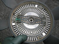
The next job was to remove the fan clutch and the "star" piece between the hub and the fan/clutch assembly. Only the G-wagens have this star piece. It's designed to have the star tines bent in the event of an emergency, into the fan clutch, so that the clutch can be locked into permanent rotation in case there is a cooling problem of failure. Pretty ingenious.

Before I did this, I removed the radiator to create more room to work in the front of the truck. That was about a 15-minute job -- four hold-down bolts at the upper radiator support, two clips at the bottom, and two transmission cooler lines to remove, as well as the lower radiator hose. Also had to unbolt a transmission cooler line that was braced through the frame of the bottom of the radiator for security purposes.

I was able to use my "hook" tool to hold the fan and clutch stationary with one hand, and use my special fan clutch socket with the other hand to pretty easily loosen the bolt, and then remove the clutch and fan. Much easier than on an M119 !!!
IMG_2065.JPG IMG_2066.JPG IMG_2067.JPG IMG_2068.JPG


Here's a view of the fan clutch. I believe I had installed it into the truck around 2019 or so.
IMG_2069.JPG

Then it was time to remove the four 10mm bolts that hold the "star" unit to the pulley. I used my pulley holder to hold things so that I could loosen the four bolts. Star piece pulled right off, as did the pulley, with some wiggling....
IMG_2070.JPG IMG_2074.JPG IMG_2075.JPG IMG_2076.JPG


Next I removed a couple of bolts on the bracket that holds the alternator and null pulley. Oil came out when I removed the first bolt, so I made a mental note that when I re-install it, I will need to use orange koala-claw anaerobic goo to coat the threads so that things don't leak.
IMG_2071.JPG IMG_2072.JPG IMG_2073.JPG


Next up was the water pump pulley. Again, the pulley holder and three 13mm bolts, and it was off the flange easy enough.
IMG_2077.JPG IMG_2078.JPG


Then I decided to remove the null pulley bracket, which bolts to the front of the timing cover (just below the cylinder head timing cover) with four 13mm bolts. It came right off.
IMG_2079.JPG IMG_2080.JPG IMG_2081.JPG IMG_2082.JPG


Then I continued removing bracket bolts (still have two left that I need to remove from under the truck), and loosening the six upper timing cover bolts.
IMG_2084.JPG IMG_2083.JPG IMG_2085.JPG


That was about it for the day. It was after 6PM, so I needed to come in and take a shower to get ready for dinner.

More soon.
 
Last edited:
What's the purpose of the metal thingy behind the fan clutch? Looks like it would lock the clutch to the pulley for full-time engagement, unless it doesn't actually touch the clutch?

1744498086777.png
 
Today I spent 3 hours 20 minutes out in the shop, doing a range of miscellaneous tasks. Here's a rundown of what I did.

The first job was to remove the power steering pump pulley. This is simply held on with three 13mm bolts. Note that I used my pulley holder tool to place tension on the pulley, to loosen the three bolts. They weren't tight, and came right off. Then it's just a matter of pulling the pulley off the hub, as shown below.
IMG_2086.JPG IMG_2087.JPG


Then it was time to remove the power steering pump, itself. First component of this task was to remove the lid of the PS fluid reservoir, and evacuate the fluid. I used a turkey baster that I keep expressly for these types of tasks. The level of the fluid was actually quite good, and it evacuated down to the top of the PS filter easily enough.
IMG_2088.JPG IMG_2089.JPG IMG_2090.JPG IMG_2091.JPG


After evacuating the reservoir, I used a 10mm tall socket and removed the center stud, which holds the fluid level plastic piece on spring tension. Then I used my hooked tool, and removed the PS filter. It was a Hengst filter, and I must have replaced it some years ago -- I'll have to look at my records as to when. The fluid, as you can see, was still of a decent reddish color. I drained the filter back into the reservoir for a few minutes before removing it and throwing it away.
IMG_2092.JPG IMG_2093.JPG IMG_2094.JPG


After that, I loosened the pressure line and the return line to the reservoir with open-end wrenches. The larger of the two connections is a 19mm, and the smaller one I believe is a 17mm. Be sure to place a rag under the connections into the reservoir/pump, to catch any PS fluid that dribbles out of the ends of the hoses, or the reservoir.
IMG_2095.JPG IMG_2096.JPG


I finished evacuating the reservoir (there were a few more turkey basters-full of fluid left after I removed the filter).
IMG_2097.JPG


Then, I tackled removing the PS pump itself from its bracket. it was held by a couple of 13mm bolts, and a 6mm Allen bolt. The fasteners weren't too tight, so were easy enough to remove.
IMG_2098.JPG IMG_2099.JPG IMG_2100.JPG


WIth that, the power steering pump and reservoir come right out !!
IMG_2101.JPG


Since I was in the area, I loosened a hose clamp for a hose going into the back of the water pump, which I'll remove later after the intake manifold comes out.
IMG_2102.JPG


Then, I switched gears over to the other side of the engine, and removed the final bolts for the alternator bracket. There were four bolts holding this bracket to the engine -- two 13mm bolts and two 6mm Allen bolts. The two 13mm bolts and one of the Allen bolts have to be removed from underneath the vehicle, and you can see a couple of photo views looking up at the bracket from underneath the truck as I prepared to remove (and then began removing) the three fasteners.
IMG_2103.JPG IMG_2104.JPG IMG_2105.JPG


The last Allen bolt is removed from above, reaching down to access it next to the crank pulley. From there, the bracket lifts up and out of the engine compartment. It's a heavy and ungainly thing !!
IMG_2106.JPG IMG_2107.JPG


Here's what the bracket looks like -- first the outside view, and then the view behind the bracket where it attaches to the block.
IMG_2108.JPG IMG_2109.JPG


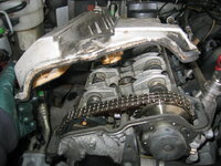
The next task was to remove the top timing cover. I had already removed all six of the bolts, but it had been RTV'd to the front of the cylinder head, and I had to use a long screwdriver as a pry bar to break it loose. Fortunately it didn't take too much effort to break the seal.
IMG_2111.JPG IMG_2112.JPG IMG_2113.JPG


With the timing cover off, you can see RTV everywhere. Sigh. Even on the o-ring at the water hose connection -- totally unnecessary. Not to mention at all of the sealing surfaces.
IMG_2114.JPG IMG_2117.JPG IMG_2118.JPG IMG_2119.JPG


Even at the green timing cover bottom seal !!!
IMG_2120.JPG IMG_2121.JPG IMG_2122.JPG IMG_2124.JPG


Timing chain top rail looked pretty decent. Definitely some grooves in it, but it had some life left. I'll be replacing it, of course.
IMG_2115.JPG


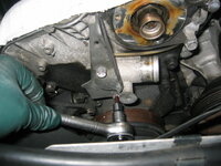
Then it was time to begin loosening, and then removing the timing chain tensioner. Before I did this, however, I used a 27mm socket on the crank bolt, and moved the engine to TDC (top dead center) per factory instructions.
IMG_2133.JPG


When I did this, I could see some previous mechanic's scratches in the cam sprocket and cam adjuster sprocket, and the chain. Interesting to see that there was zero stretch from where it had been marked previously. Timing chain stretch is almost NEVER a problem on the M104, because the chain is so short and direct.
IMG_2116.JPG IMG_2134.JPG IMG_2135.JPG


After viewing these marks, I loosened and then removed the timing chain tensioner. Here's a view of the tensioner right before I began removing it.
IMG_2110.JPG


And the timing chain tensioner removal process.
IMG_2126.JPG IMG_2127.JPG IMG_2128.JPG IMG_2129.JPG IMG_2130.JPG


Disassembling the tensioner briefly after removing it from the engine. NOTE: With the M104 timing chain tensioner, it MUST BE COMPLETELY DISASSEMBLED, AND THEN RE-ASSEMBLED, BEFORE REINSTALLING IN THE ENGINE. This ensures that the tensioner is fully reset. If you don't do this, you will snap one of the camshafts.
IMG_2131.JPG IMG_2132.JPG


After removing the timing chain tensioner, I opted to remove the serpentine belt tensioner. It is held on by four 6mm Allen bolts -- easy enough to remove.
IMG_2136.JPG IMG_2137.JPG


Then I removed a couple of the bolts that hold the water pump bracket to the side of the block. I'll complete this disassembly after the intake manifold is removed from the truck, as it makes access to a couple of the water pump bolts difficult. There's a third, sneaky little 10mm bolt at the back that holds the side corner of this pump bracket, to another bracket, as shown in the third photo below. You can't quite see the head of the 10mm bolt in the center of the photo, but believe me, it's there....
IMG_2138.JPG IMG_2139.JPG IMG_2140.JPG


I used some of my wife's nail polish (white and pink colors) to add two extra sets of marks on the timing chain and sprockets, to augment the difficult-to-see scratches that the previous mechanic had made.
IMG_2141.JPG


Beginning to wind down, I removed the fuel pressure regulator with a pair of snap-ring pliers. I had replaced this item some years ago, and it was a Bosch item that was made in Brazil. I will probably replace it with a NOS unit in my parts stock that was made in Germany.
IMG_2142.JPG IMG_2143.JPG IMG_2144.JPG IMG_2145.JPG


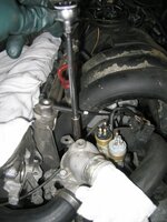
Before finishing up, I removed a few more exhaust manifold bolts, as well as one of the two downpipe bolts on the front exhaust manifold. All four of the downpipe bolts are rusty, and although they are a 12mm head, they have so much rust that you literally have to use a hammer to POUND a six-point socket onto the head of the bolt, displacing the rust. It took a lot of effort, but I got the first of the four downpipe bolts removed (after soaking for a couple of days in Kroil), and it was not fun nor easy. Three more to go. Then I can remove the first of the two exhaust manifolds.....

That's all for now. More later.
 
This morning I put my second parts orders in with both MB Annapolis, and FCP Yurro. I'll be putting in an order shortly with AutohauZ specifically for the fuel injector o-rings. MB wants nearly $5.00 each for them, and while FCP had them for $1.99 each a few days ago, they seem to be gone from their catalog now. AutohauZ has them for a good price, so I'll order up six of them.

Into this job at about $1,500 for parts so far, including $175 or so for a Graf water pump that I had purchased many years ago. I am going to proactively replace the water pump and all three coolant temp sensors that screw into it, as well as the thermostat.

The Graf water pump is used in common with only one other model, the 3.2L M104 as used on the 1992-1993 300SE, and the 1993-1995 S320 (both W140 models). So it is not a horrible thing to obtain, if needed, though I've been sitting on my Graf pump for probably the past 5-6 years. I will keep the original pump, as it is not leaking and seems to be working fine.

For now, I am going to hold off on purchasing a new A/C compressor. I don't see any obvious leaks from the old compressor (i.e. the manifold connection on top, or the shaft seal), which I had installed in 2017 right before coming to Maryland, but for some reason, there is a pretty significant A/C refrigerant leak in the system that happened sometime around 2020 or 2021. The receiver-drier and the Tx valve are also both new factory units when I had the compressor done. Inspection of the condenser (which surprising, is still available from MB at $750 discounted!!) also isn't showing any obvious refrigerant leaks. I haven't diagnosed where it came from specifically, so if it is not any of those items, it must either be a line/connection (probably the most likely) or the evaporator -- something I need to look at and diagnose. I don't even know where the evaporator is on the G-wagen, so I have some research to do. Hopefully, wherever it is, it isn't as much of a PITA to get to as it is on the W124.....

That said, the A/C compressor is a standard Denso 471-1224 unit, which is extremely common and used in common with the US E320 M104s.

As with my other Top-End and Engine Bay refreshes, pretty much everything under the hood that is soft (rubber or plastic) is going to get replaced with a new factory part. That includes all hoses (and I'm going to try to get to the heater hoses, when I have the cylinder head off), vacuum lines, intake hoses at the manifold, intake manifold rubber parts and clamps, and of course the intake and exhaust manifold gaskets (including the intake manifold resonator gasket). New Elring valve cover gasket is in hand already.

I will be taking the valve cover, now that it is fully disassembled, in to Chesapeake Coatings up in Halethorpe MD (just on the southern edge of Baltimore) this week to have it blasted and then powder coated.

Looking ahead to the coming days, I need to finish removing the exhaust and intake manifolds from the cylinder head. MB says that you should leave everything connected and lift the entire "loaded" cylinder head out of the vehicle with a block and tackle, but with I did my previous M104 job in 2014, I found that removing everything from the head while it is in the car is not that big of a deal, and it allows one person to lift and place the cylinder head atop the engine when re-installing it. The M104 cylinder head is heavy (heavier than a single M117 or M119 cylinder head), but it is within the capacity of a single man (or two) to lift and move around.

When the cylinder head comes off the block, I'll consider the job about 40% done. While it is away being refurbished and cleaned, I will clean the engine bay and gently scrape the pistons and the block surface. Will try to clean the block as well.

Right now, I'd say the job is around 15-20% done, total. Making steady headway, but there is A LONG way yet to go.

For reference, the 2014 M104 cylinder head job took me around 60-65 hours. I didn't replace the front crank seal on that job, though.

Which reminds me ... I need to procure an M104 flywheel lock!!! Dang.

:update:
M104 flywheel lock tool has been purchased. Fortunately it isn't expensive -- ~$40 or so. It also applies to M102, M103, and various diesel models. Perhaps someone would be interested to purchase it after I'm done, if they have an M104 or other model they could use the tool for.
 
Last edited:
Tonight I only spent 1 hour and 10 minutes out in the shop, but I got a lot done, and worked through one problem that I've had for the past few days.

Here's how things went:

First, I removed the third coolant temperature sensor, which was a horizontally placed, two-pin sensor, that screwed into the back of the water pump. I have ordered a new sensor to replace this one, which is likely the original unit.
IMG_2147.JPG


From there, I decided to tackle the problem that has been bothering me for the past week or so - the final, remaining lower rear bolt that held the fuel rail + the intake manifold to the cylinder head. It was exceedingly difficult to get a proper purchase on this 6mm Allen bolt (one of nine that hold the fuel rail and intake to the head), because the aluminum oil filter housing was in the way. This meant that it was nearly impossible to get a good angle to get a 6mm Allen socket or key into the head of that bolt. And, the short end of an Allen key wouldn't work, because there wasn't enough rotational room to move it to loosen the bolt.

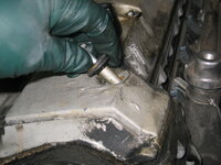
I succeeded in stripped the head out, and despite many attempts with many different tools, I was FINALLY successful in getting it out by pounding in a T-50 Torx socket, on a long 3/8" socket extension, into the stripped-out Allen head of the bolt. I got enough of a bite on it, finally, that I was able to turn it loose CAREFULLY with a long-handled 3/8" ratchet and some constant pressure. WHEW.

With the removal of that final bolt, I was able to lift the fuel rail up and out of the engine compartment, straightaway. I placed it outside of the garage so that the fuel could evaporate.
IMG_2148.JPG IMG_2149.JPG


But, I had two more tasks to do, before removing the accompanying intake manifold. First, I had to remove the two breather hoses that attach to the large nipples on the bottom side of the plastic intake manifold. I had to be VERY careful with these nipples, and levering the hoses off of them (this led to a MAJOR debacle in my 2014 rebuild, where I broke a nipple off and had to purchase a wrecking yard manifold to "harvest" the nipple assembly, then glue it to the intake), but was successful. Fortunately, the hoses were semi-fossilized, but after removing the clamps, I was able to lever them off the nipples with a large flat-blade screwdriver, cracking/breaking them in the process.

No worries on this -- I had a new hose of each on this morning's parts order from MB. They are cheap -- each hose was less than $12.00, discounted. Here is what the two clamps looked like, holding the hoses on the nipples, immediately before I loosened them and then prised off the hoses.
IMG_2150.JPG


The second job was to remove the second knock-sensor plug, which uses a lead off of the main upper wiring harness that goes DOWN THROUGH the intake manifold's runners in the center (adjacent to the ETA), and down onto the block, where there is a plug. I had to carefully reach down there with the manifold partially off, and release the wire security connector that held the plug to the sensor. Took a little bit of doing, but finally got it.

With that, the black plastic intake manifold came up and off the engine, as below.
IMG_2151.JPG IMG_2152.JPG


Here are a couple of views of the engine compartment with the intake manifold off the engine. First, the intake area under the manifold (I had cut the semi-fossilized black rubber ETA boot partially to give me a better angle at one of the intake manifold Allen bolts). And second, a close-up of a couple of the air intakes in the cylinder head leading down to the valves.
IMG_2153.JPG IMG_2154.JPG


The last small job of the night was to remove two of the four main water pump bolts -- all being 6mm Allen bolts. I also removed the two 10mm small bolts that held a metal water pipe to the back side of the water pump.
IMG_2155.JPG

That was it for the night.

Next up I will remove the lower half of the intake manifold from the block, as well as the ETA and such. More work to do on the lower row of bolts on the exhaust manifolds -- one remaining lower bolt (it's loose and almost out) on the forward exhaust manifold, and three remaining bolts on the underside of the rear exhaust manifold.

After those bolts are removed, along with the three remaining downpipe bolts, then I should be ready to loosen and then remove the cylinder head. Hoping I'll have that part of the job completed by the end of this weekend.
 
Spent an hour out in the shop last night and removed the ETA and did some other miscellaneous tasks. Took photos but so few, it didn't make sense to do a separate post.

Today (Friday) I got my latest parts order in from MB Annapolis. Everything was available and provided. Parts availability for the M104 engine still seems to be -- honestly -- pretty excellent. I also got a G320-specific lower radiator hose, which is a 463-chassis-specific part, and it was available, albeit for the price of $151 discounted. It was made in 2023, so still relatively recent production. The original hose is still working fine (and I will keep it), but it's old and tired ... and 30 years old now. So, it needed to be replaced.

An order from FCP Yurro will arrive on Monday, with an ETA gasket, a couple of coolant temp sensors (OEM) that are NLA from MB, and a new timing chain tensioner from OEM INA. I still have to get the fuel injector o-rings from AutohauZ, but I'll do that later and see if there are any other parts that I would need to order from them. MB wants huge bucks for their FI o-rings.

Next tasks are to complete removal of the water pump and bracket, the intake manifold, and the two exhaust manifolds, and then the cylinder head can come off. I will bring the valve cover to the powder coating shop for blasting and coating probably next week. If really ambitious, and get the cylinder head off the car this weekend (may or may not happen), I'll remove the cams and buckets, and take that into the machine shop for cleaning and refirb. I have some other metal parts that I'll have the machine shop clean up as well, such as the upper timing cover, the alternator and power steering pump brackets, and so forth.

So, things progress, slowly but surely. I should have another good update in the near future.
 
.An order from FCP Yurro will arrive on Monday, with an ETA gasket, a couple of coolant temp sensors (OEM) that are NLA from MB, and a new timing chain tensioner from OEM INA.
The FCP Yurro box arrived today (Saturday). A smorgasbord of COOs for the parts therein:
  • Coolant temp sensor #1 - Facet brand - made in Italy (NLA from MB)
  • Coolant temp sensor #2 - Mahle Aftermarket brand - made in Mexico (NLA from MB)
  • ETA gasket (I bought three; also fits M119 ETA) - Elring brand - made in Poland
  • Thermostat - Wahler brand (Borg Warner Aftermarket Europe) - made in Brazil
All of these parts used to be made in Germany. I was especially surprised to see Elring parts being made in Eastern Europe. I know for a fact that the old Wahler thermostats were made in Germany. I will have to look at the old one that I installed in 2021 or so, but I think it is a Germany thermostat. I may just re-use it and keep this Brazil Wahler unit as a reserve.
 
Back
Top