• Hi Guest !

    Welcome to the 500Eboard forum.

    Since its founding in late 2008, 500Eboard has become the leading resource on the Internet for all things related to the Mercedes-Benz 500E and E500. In recent years, we have also expanded to include the 400E and E420 models, which are directly related to the 500E/E500.

    We invite you to browse and take advantage of the information and resources here on the site. If you find helpful information, please register for full membership, and you'll find even more resources available. Feel free to ask questions, and make liberal use of the "Search" function to find answers.

    We hope you will become an active contributor to the community!

    Sincerely,
    500Eboard Management

Vacuum elbow

darek_u

E500E Guru
Member
I need some help. I'm slowly replacing all of the vacuum rubber elements, I have only very few left to do. I got stuck with this one - the number stamped on this elbow itself leads to a 30 deg elbow, I believe I need 90 deg one. On top of that the existing element seems to be little too large, thus zip ties in place. I looked through EPC but it is not very clear on which element should be installed. can someone help me here?
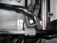
IMG_0715.jpg
 
Hi,
part no. A1190780081, it is no.35 on the drawing of the vaccum system.
The part it attaches to is mounted with the junction to the wrong side. It should point to the right on your picture, that would change the angle too (it cannot be just turned, you will have to detach it an switch the connecting sides).
 
The correct rubber elbow part number is 1190780081 for this application.

It appears to me that the large black Tecalan hose is mis-routed and thus had to be clamped on with zip-ties. A mechanic botch job.

Please take a look at my Top-End Refresh thread, where I rebuilt all of this with the correct routing of all of the vacuum lines.

Post is here.

img_1027-jpeg.112076


img_1028-jpeg.112077


img_1038-jpeg.112601
 
Last edited:
Can you please explain what for a construction this is?
Normally, that is the fuel pressure "bung" fitting test port to measure the pressure (Kraftstoffdruck).

My nitrous-oxide system (Lachgasspritzung) uses that fitting to monitor fuel pressure for safe operation of the nitrous injection system. The gas will not be injected if the fuel pressure is not high enough.

It is one of several "safety" mechanisms of the system so that the engine is not burned up.

Here is a technical explanation of how it is set up:
  • Funktioniert: the fuel pressure monitoring subassembly is the final logic switch that permits the flow of nitrous to reach the engine. Upon nitrous activation, only solenoid #1 opens. Some of the nitrous is used to apply pressure to the fuel pressure regulator. The fuel pressure monitoring subassembly closes an electronic switch (the Hobbs switch) once the prescribed fuel pressure has been reached. The Hobbs switch opens solenoid #2 and allows nitrous to reach the engine.
 
Last edited:

Who has viewed this thread (Total: 1) View details

Who has watched this thread (Total: 3) View details

Back
Top