• Hi Guest !

    Welcome to the 500Eboard forum.

    Since its founding in late 2008, 500Eboard has become the leading resource on the Internet for all things related to the Mercedes-Benz 500E and E500. In recent years, we have also expanded to include the 400E and E420 models, which are directly related to the 500E/E500.

    We invite you to browse and take advantage of the information and resources here on the site. If you find helpful information, please register for full membership, and you'll find even more resources available. Feel free to ask questions, and make liberal use of the "Search" function to find answers.

    We hope you will become an active contributor to the community!

    Sincerely,
    500Eboard Management

ABS and ASR lights on

RobertK

RobertK
Member
Hello,
I am still struggling with the issue that my ABS and ASR are going on simultaniously on my Japan import 500E of 1992 after driving a few meters.
A lot of forum threads are about this problem and what you should check but unfortunately I have still no adequate solution.

The following things are replaced or done in the last few years trying to solve this issue:
Of course after reading out via MB HHT by a garage and gathering information on this forum over time:

ABS sensors replaced right front wheel and right rear wheel for new (OEM) ones.
Ignition switch replaced by a new (OEM) one.
Brake light switch S9/1 ABS relay replaced for a new one (A 001 542 70 19).
Fuses replaced in the specific module with the 4 fuses on top of it.
The plug connections has been renewed in the area of the fuel pump.
Checking the connectors of the ASR module, taking out the module and replace it back.

I have purchased myself a 38-pin Blink code reader in the meantime.

When I try to read out the Anti-Lock Brake System (socket 6) the following error-codes pop-up (Count of green blinks):
3 => Right front axle vehicle speed sensor signal ??? (has been replaced already)
30 => CAN data line to electronic accelerator/cruise control/idle speed control module

That last one, what does this exactly mean ? ETA ?
(I have to mention also that my cruise control does not function at all but that is for me less high on my priority list but perhaps there is a correlation between the two problems)

Robert
 
Last edited:
There could be a wiring issue to the right front speed sensor. Check that next.

You also need to verify the car has the correct ABS/ASR module part number installed that matches your VIN. It's possible that a wrong module could cause problems.

Ignore code #30, this is a generic/ghost code that always appears whenever limp mode is triggered.

And, if your cruise control does not function, also verify your E-GAS module is the correct part number. No fault codes from the E-GAS module?

:cel:
 
And, if your cruise control does not function, also verify your E-GAS module is the correct part number. No fault codes from the E-GAS module?
That is pin 7 think ? Mercedes OBD1 diagnostic codes - 1988-1995 document is not clear on that for the W124. It shows for the W124 on the 8-pins socket, not the 38-pins.
Checking Pin 7 shows diagnostic code 14: Closed throttle position contact switch
 
Last edited:
That is pin 7 think ? Mercedes OBD1 diagnostic codes - 1988-1995 document is not clear on that for the W124. It shows for the W124 on the 8-pins socket, not the 38-pins.
Yes, E-GAS is pin #7 of the 38-pin connector.

Please use the PDF files found here, do not use ANY other documents for codes on the 500E:

 
Code 14 is for S29/3, details here:

 
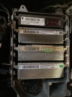
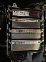
See the attached photo of the modules in my car.
My car has VIN: WDB1240361B809659

No idea or these ASR and E-Gas modules are the matching numbers regarding my VIN.
 

Attachments

  • photo_modules.jpeg
    photo_modules.jpeg
    2.7 MB · Views: 13
Last edited:
See the attached photo of the modules in my car.
My car has VIN: WDB1240361B809659

No idea or these ASR and E-Gas modules are the matching numbers regarding my VIN.
That's helpful! Looks like the modules are correct. I'd start by eliminating E-GAS code 14 for S29/3.

If you keep getting ABS code 3 (speed sensor), you'll need to check the wiring between the module connector and the sensor connector.

:detective:
 
Yes, thanks good idea to do that in that order. I have ordered a new Closed throttle position contact switch and after installing that brand new one, I will look further to that right wheel sensor.

BTW: ASR light does never blink up during accerelation (except during startup) so that has probably the same reason. That could be also due to the faulty of the Closed throttle position contact switch I red in earlier threads.
 
I have replaced the Closed Throttle Position contact switch for a new one. Unfortunately not the result what I expected.
After replacement and a testdrive: ASR + ABS lights simultanously lights up after several meters driving (forwards) like before. Before I did the testdrive I had deleted the codes for pin #7 (was already empty ??) and #6 of the 38-pin connector.

During the testdrive I noticed that my Cruise Control is still not working.

After the testdrive, I have read out the codes for modules #7 again, this was empty.
Module #6 gave the same error as earlier: 3=> Right front axle vehicle speed sensor signal.

Next step is to check the wiring from that right front speed sensor to the module connector.
 

Attachments

  • IMG_2042.jpeg
    IMG_2042.jpeg
    1.8 MB · Views: 5
Do you have access to SDS with HHT-Win? This will show you live data, including individual speeds at each of the 4 wheels. This would prove if you have 3 good signals and 1 bad signal, although once confirmed, you're back to chasing the 1 bad signal.

Is there any way you can obtain a spare ABS/ASR module to swap in?

:scratchchin:
 
FWIW, I had a 400E once where the cruise control failed and it turned out to be the engine wiring harness. I happened to notice that with the key on and engine off, leaning on the air filter housing caused the ETA motor to activate and whine. After removing the housing I was able to narrow the problem to the engine wiring harness. After changing the engine wiring harness the cruise control worked. Maybe I missed it in the above string but how old is your wiring harness? Maybe your CC issue isn’t related to your ABS/ASR lights.
 
Do you have access to SDS with HHT-Win? This will show you live data, including individual speeds at each of the 4 wheels. This would prove if you have 3 good signals and 1 bad signal, although once confirmed, you're back to chasing the 1 bad signal.
No, I do not have that.

Is there any way you can obtain a spare ABS/ASR module to swap in?
Yes I have a spare one with the same number if you mean the module with only ASR on it. In my case the second one from above I think you mean, see photo:
 

Attachments

  • photo_modules.jpeg
    photo_modules.jpeg
    2.7 MB · Views: 6
Last edited:
FWIW, I had a 400E once where the cruise control failed and it turned out to be the engine wiring harness. I happened to notice that with the key on and engine off, leaning on the air filter housing caused the ETA motor to activate and whine. After removing the housing I was able to narrow the problem to the engine wiring harness. After changing the engine wiring harness the cruise control worked. Maybe I missed it in the above string but how old is your wiring harness? Maybe your CC issue isn’t related to your ABS/ASR lights.
My wiring harness on top has been already renewed before I purchased the car 6 years ago and the below harness has been 3 three years ago renewed. I think you are right, these issues are not been related to each other.
 
Have you bled the brake system, including the ABS/ASR port? When the ABS and ASR lights illuminate is it after the brake pedal is pressed or is it just a function of driving it a few meters even without braking?
 
Have you bled the brake system, including the ABS/ASR port? When the ABS and ASR lights illuminate is it after the brake pedal is pressed or is it just a function of driving it a few meters even without braking?
I do not understand what you exactly mean by bled the brake system. My brake fluid was serviced 1,5 year ago following the instruction for also replace the brake fluid of the ABS/ASR pump. Done by a MB Classic Center.

The ASR and ABS lights illuminate most time directly when I drive 5 meters forwards. And because of driving out of my garage I have used the brake pedal, yes.
But it illuminate when I drive a bit forwards and not backwards. Sometimes it does not illuminate directly in that way but after driving for example 10 of 15 kilometres or sometimes more.
 
Last edited:
Is there any way you can obtain a spare ABS/ASR module to swap in?
I have swapped the spare module into the car. Before I did this I cleared the code of pin #6. I disconnected also the battery before swapping it.
Same result/behaviour after driving a bit regarding the illumination of the lights. The limb-mode was noticable directly.

Reading out codes pin #6 afterwards:
Codes 3, 13 en 30 (limb-mode, that last one can be ignored I understand)

Code 13 refers to the Stop Lamp Switch (S9/1). I have earlier already replaced this one for a new OEM one.
 
Last edited:
I do not understand what you exactly mean by bled the brake system.
It's been a long time but I believe Captain @Trae had an issue with his ASR light illuminating that he solved by bleeding/servicing the brake hydraulic system. Perhaps you got some air in the system. Something to consider anyway. The charge pump under the brake master cylinder stopping prematurely or not operating correctly can cause an ASR light too. Check the connection there.

Post in thread 'ASR Light'

Also, a bad voltage regulator has been known to cause all kinds of warning lights to illuminate. It happened to me and when I checked the voltage at the battery with the engine running it was over 19 volts. Maybe you can get someone in the trunk to measure it as you drive forward until the lights illuminate and see if there are any voltage spikes. It doesn't cost anything to check. :shocking:
 
Last edited:
It's been a long time but I believe Captain @Trae had an issue with his ASR light illuminating that he solved by bleeding/servicing the brake hydraulic system. Perhaps you got some air in the system. Something to consider anyway. The charge pump under the brake master cylinder stopping prematurely or not operating correctly can cause an ASR light too. Check the connection there.

Also, a bad voltage regulator has been known to cause all kinds of warning lights to illuminate. It happened to me and when I checked the voltage at the battery with the engine running it was over 19 volts. Maybe you can get someone in the trunk to measure it as you drive forward until the lights illuminate and see if there are any voltage spikes. It doesn't cost anything to check. :shocking:
Thank you for the tips !

Do you have perhaps a photo or something of that charge pump under the brake master cylinder ?
I cannot visualize and imagine what you exact mean.
 
Thank you for the tips !

Do you have perhaps a photo or something of that charge pump under the brake master cylinder ?
I cannot visualize and imagine what you exact mean.
There is a thread about it here on the forum.


Thank you for the tips !

Do you have perhaps a photo or something of that charge pump under the brake master cylinder ?
I cannot visualize and imagine what you exact mean.
img_1704-jpg.143248


img_1705-jpg.143249
 
I certainly don’t mean to over-simplify this but I believe I solved my similar ASR /ABS issue by changing the brake light bulb. I read elsewhere in the Forum that poor ground can cause the stop light switch code and to check grounds - I started at the brake light end. Found a dim bulb. (Yes, I know I am another😳). Seems to have worked as I too was not getting too far down the road.
 
I certainly don’t mean to over-simplify this but I believe I solved my similar ASR /ABS issue by changing the brake light bulb. I read elsewhere in the Forum that poor ground can cause the stop light switch code and to check grounds - I started at the brake light end. Found a dim bulb. (Yes, I know I am another😳). Seems to have worked as I too was not getting too far down the road.
You mean you got rid of an ASR-fault by simply replacing the brake light bulbs (in the tail light housings)?
 
Thanks for all your tips everybody !

The first step I will take is to check the wiring of the right front speed sensor to the module and the tooth ring where the sensor is connected.
That code 3 (at pin #6) is continously popping up indeed.
 
You mean you got rid of an ASR-fault by simply replacing the brake light bulbs (in the tail light housings)?
That’s what it would appear. Just replaced two days ago and things have been okay.

I’m too old to confuse correlation with causation. I might have caused a better ground situation somewhere within the bulbs housings and associated wirings as I pulled both side’s housings and swapped bulbs, etc. as I tried to discern bulb good/fails states.

I read and cleared the fault codes. (Cruise Control subsystem threw off similar codes for stop light switch and had also failed once ASR/ABS panel lights lighted.)
But in my case error code 3 (pin #6) pops up repeatedly after clear the code's and driving again. How does this relate to each other ?
Were your error code's a misrepresentation of the facts ?
 
I have been checking the front right speed (ABS) sensor. Unscrewing the sensor I noticed nothing unusual. The sensor was not very dirty. Checking the ABS wreath I see not damage or something. Not very dirty too.

Checking the wiring of the sensor towards the engine compartment. No damages in the wiring. It is a new sensor like I earlier stated. The cable looks very new.
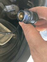
Following the wire of the sensor, I disconnected the plug, see photo. Following the wire it goes to an wire case with more cables in it, one direction to the ground wire, see second photo and the + go the other towards the module I suggest.

What en how do I have to investigate this further ? Do I have to measure some pins in the connector of the module (which one) and how do I do that ?
 

Attachments

  • IMG_2049.jpeg
    IMG_2049.jpeg
    1.6 MB · Views: 7
  • IMG_2050.jpeg
    IMG_2050.jpeg
    1.8 MB · Views: 6
What en how do I have to investigate this further ? Do I have to measure some pins in the connector of the module (which one) and how do I do that ?
Yes. You need to verify that the 2 sensor wires have continuity to the connector at the base of the CAN module, which is what the ASR module plugs into.

Compare readings from the opposite front wheel / sensor.

Pinout document is here:


:matrix:
 
Yes. You need to verify that the 2 sensor wires have continuity to the connector at the base of the CAN module, which is what the ASR module plugs into.

Compare readings from the opposite front wheel / sensor.

Pinout document is here:


:matrix:
For my understanding: seeing the pinouts on the N30/1. My voltmeter should be on pin 13 (-) and 34 (+) with contact on and turning the wheel or something should give a certain voltage ? Is that right ?

Can you please otherwise explain in detail how I can check this ?
 
That sounds correct. I'd first check for continuity (resistance / ohms) at pins 13 and 34, to the round connector barrel. Should be near zero ohms for both.

Assuming that checks out ok, you can put a voltmeter at pins 13 + 34 and spin the wheel by hand. Voltage should increase with wheel speed. I believe you'll need to measure AC voltage as the signal is likely a square wave, not DC? I haven't personally done this so I'm not sure what to expect.

If anything doesn't seem kosher, compare to the left speed sensor, pins 10 and 30.

:detective:
 
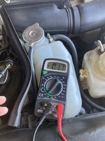
I have measured resistance /ohms first at pin 13 and 34

Here are the results:
Pin 13 => no restistance measured at all = Not good
Pin 34 => Minimal restistance measured = Good
See photos.
I double checked this by measuring the voltage when I turned the right wheel with the pin on 13 (-) and 34 (+)
Also 0, no result in an increase in voltage when I turned the wheel.

It seems to me that I have a cable break at the - wire (13) towards the plug.

It looks to me a hell of a job to fix this. Could you give me please some instruction ?
 

Attachments

  • PIN_34.jpeg
    PIN_34.jpeg
    1.5 MB · Views: 8
  • PIN_13.jpeg
    PIN_13.jpeg
    1.6 MB · Views: 8
It does appear you have an open wire on pin 13. 🫣

I have no idea how to trace where the fault in the wire is located. You can try to follow the wires as far as they are visible, but once they disappear into the chassis, it may be difficult. If you cannot trace the entire length you may need to splice in a new wire to replace the bad one.

:runexe:
 
Allright, I have started with unleash the CAN-box to see something more from that side.

Does anyone know how to make this plug open without breaking it ? (see photo)
 

Attachments

  • IMG_2061.jpeg
    IMG_2061.jpeg
    1.6 MB · Views: 10
Just another avenue to explore having seen a reference to brake bleeding.

In 1998 I bought from MB dealer a 124.051 300CE-24. After a very short while the ASR light would come on (can't remember if the ABS light came on too).

Just before the light came on, I was aware of a light drumming sound from the engine compartment which stopped when the light came on.

I took it back to MB and they said they solved the problem by repeated bleeding of the brake system in its entirety.

And all's well to this day.

Just a thought.

RayH
 
Last edited:
Allright, I have started with unleash the CAN-box to see something more from that side.

Does anyone know how to make this plug open without breaking it ? (see photo)
I believe the connector does not "open", but the metal sockets can be removed individually by releasing the retaining clip that holds them into the holes?

BTW - when checking low resistance, select the lowest range on your meter. On the meter shown this would be the "200" ohm setting. Readings for good wires should be near zero (say, 0.1 or 0.2 ohms). Usually anything below 1.0 ohms is ok, the discrepancies tend to be from the meter itself, or from the leads / contact points.

:klink:

1747065568748.png
 
Allright I will check that again with that setting.

To bypass this wire towards the plug should be a possible solution, but the problem can also be in the plug.

Replacement of the whole ASR wiring could also be a solution but I think A124 543 60 27 is NLA.

1747066353552.png
 
I believe the connector does not "open", but the metal sockets can be removed individually by releasing the retaining clip that holds them into the holes?
I am not succesfull in removing that two metal sockets (13 and 34). Is there a special tool needed to release the retaining clip ?
I have tried this with a small nail but that did not work unfortunately.
 

Attachments

  • IMG_2061.jpeg
    IMG_2061.jpeg
    1.6 MB · Views: 6
I believe there is a tool used to release the retaining clip, unfortunately I don't know the shape or dimensions needed. I'm also not sure if the tool is needed on both sides of the connector (see photo) or only one side. Someone must have been down this road before.. wish @Klink was still posting here, he'd know!

1747488816415.png
 
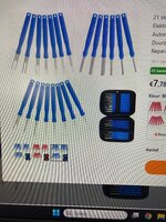
I will try to loosen this connectors with the following ordered tools.
I hope this works fine.
Then I can judge which connectors I need to buy.
 

Attachments

  • Tooling.jpeg
    Tooling.jpeg
    1.3 MB · Views: 2
Good news !
I have found the error I think. This plug seemed to be the cause. I have replaced this with one of the scrap-yard and soldered it between the wires. And now I measure a low resistance on the - wire (34) instead of OL.

Building everything back and doing a short test-drive looks promising. The ASR and ABS light does not light up.
 

Attachments

  • IMG_2049.jpeg
    IMG_2049.jpeg
    1.6 MB · Views: 9

Who has watched this thread (Total: 3) View details

Back
Top