Disclaimer:
These instructions are meant to be a supplemental guide to the instructions provided by Mercedessource, not a full motor removal tutorial. Also, don't be offended if it feels like I'm over explaining things. I rather sound redundant than opaque.
This is my 1993 300ce. Recently, the A/C stopped working. After testing many fuses
and pushing many buttons, I was fairly confident the blower motor was the culprit.

I used Mercedessource to get the motor and instructions for how to "dig" the motor out of the car.
https://mercedessource.com/store/124-chassis-heater-and-ac-motor-repair-manual-kent-bergsma-download
https://mercedessource.com/store/12...osch-heater-motor-w-instructions-install-tool
The instructions for getting the motor out of the car were quite good and I had little difficulty, but his method of removing the fans from the motor was another matter. The extensive corrosion on the motor shafts [Picture 13] made using the hammer and modified wrench ineffective. To get around this, my father suggested building a small press tool to slowly screw the fan off the shaft... So I did. [picture 9]
To use this method, first drill an indent into the center of the old motor's drive shafts. This will seat what I'll call the 'pushing bolt' and keep it centered.

Next, find a bolt at least 2 inches long and with a diameter at least 2 millimeters shorter than the inside diameter of the squirrel cage fan. [The one I show in the images below is too fat and too short. I ended up having to use a different one to remove one of the fans]. Depending on how thick it is, you may have to grind it down as shown below.
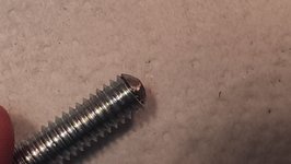
The materials I used to make the rest of the tool are shown below [Picture 8]. The tool can be built more simply and with fewer components if you have access to the proper drills and metal plate. The only reason I didn't is because I was determined to use things I could find in the garage. Make sure you understand how the tool is used before you begin construction.
If you have the plate metal and wish to use it, cut 2 disks out of it roughly the same size as the largest washers shown in picture 8. The size doesn't have to match exactly, but it does need to be big enough for the slim bolts to pass through the spokes of the fan and small enough for the slotted disk to fit between the motor and fan. Drill a hole
slightly larger than the drive shaft in the center of the disk that will become the slotted disk. Then cut a channel from the center hole to the outer edge so it can be place between the motor and fan around the drive shaft. Find a nut that fits the Pushing Bolt
from pictures 6-7. Drill a hole in center of the other disk (which I will call the Pushing Disk from now on) that is slightly smaller than the outside diameter of the nut, but slightly larger than the inside of the nut. The disks should then be clamped together to drill the holes for the slim bolts. These holes should not be exactly at 0, 120, and 240
degrees. The fan has 13 spokes and the placement of these bolts should reflect this. Make sure the long slim bolts are at least 3 inches long. Their radius should be as small as possible while still being resistant to bending. [Optional] After the slim bolt holes are drilled, tack weld the Pushing Nut over the center hole on the Pushing Disk. Construction using washers is roughly the same only slightly more annoying.

I used super glue to hold the washers together because I'm lazy and the forces applied to the tool while in use will pull everything together, meaning not much adhesive strength is needed. But, I would suggest tack welding the washers together or just cutting a circle out of plate steel. This is a shot of the tool assembled without being on the blower motor assembly:
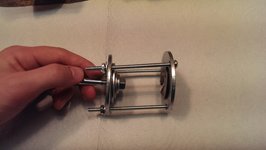
The tool is used by first placing the slotted disk onto the motor drive shaft between the motor and the fan[Picture 10]. Next, the long slim bolts are fed through the holes in the slotted disk. Slide the Pushing Disk onto the slim bolts followed by the nuts for the slim bolts. Make sure the Pushing Bolt is secured by it's nut and the Pushing Disk before fully tightening the pushing disk to the drive shaft. Note, a wrench will have to be on
Pushing Bolt's nut while pulling the fan off of the shaft. This may require the bending of a wrench or cutting a chunk out of the Pushing Disk.

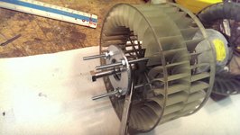

Then, it's a simple matter of holding the wrench steady while tightening the Pushing Bolt into the drive shaft, forcing the slotted disk to pull the fan off.
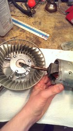

And we're done!... with one relatively small part of the blower motor replacement...
Anyway, the instructions provided by mercedessource work very well for getting the old fans on the new motors.
Let me know if you have any questions or have spotted any errors.
These instructions are meant to be a supplemental guide to the instructions provided by Mercedessource, not a full motor removal tutorial. Also, don't be offended if it feels like I'm over explaining things. I rather sound redundant than opaque.
This is my 1993 300ce. Recently, the A/C stopped working. After testing many fuses
and pushing many buttons, I was fairly confident the blower motor was the culprit.

(Picture 1)
I used Mercedessource to get the motor and instructions for how to "dig" the motor out of the car.
https://mercedessource.com/store/124-chassis-heater-and-ac-motor-repair-manual-kent-bergsma-download
https://mercedessource.com/store/12...osch-heater-motor-w-instructions-install-tool

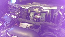
(Picture 2. Removing the blower motor. I don't know why the picture is purple)
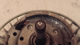
The instructions for getting the motor out of the car were quite good and I had little difficulty, but his method of removing the fans from the motor was another matter. The extensive corrosion on the motor shafts [Picture 13] made using the hammer and modified wrench ineffective. To get around this, my father suggested building a small press tool to slowly screw the fan off the shaft... So I did. [picture 9]
To use this method, first drill an indent into the center of the old motor's drive shafts. This will seat what I'll call the 'pushing bolt' and keep it centered.

(Picture 3)

(Picture 4)
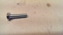
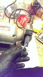
Next, find a bolt at least 2 inches long and with a diameter at least 2 millimeters shorter than the inside diameter of the squirrel cage fan. [The one I show in the images below is too fat and too short. I ended up having to use a different one to remove one of the fans]. Depending on how thick it is, you may have to grind it down as shown below.

(Picture 5)

(Picture 6)

(Picture 7)
The materials I used to make the rest of the tool are shown below [Picture 8]. The tool can be built more simply and with fewer components if you have access to the proper drills and metal plate. The only reason I didn't is because I was determined to use things I could find in the garage. Make sure you understand how the tool is used before you begin construction.
If you have the plate metal and wish to use it, cut 2 disks out of it roughly the same size as the largest washers shown in picture 8. The size doesn't have to match exactly, but it does need to be big enough for the slim bolts to pass through the spokes of the fan and small enough for the slotted disk to fit between the motor and fan. Drill a hole
slightly larger than the drive shaft in the center of the disk that will become the slotted disk. Then cut a channel from the center hole to the outer edge so it can be place between the motor and fan around the drive shaft. Find a nut that fits the Pushing Bolt
from pictures 6-7. Drill a hole in center of the other disk (which I will call the Pushing Disk from now on) that is slightly smaller than the outside diameter of the nut, but slightly larger than the inside of the nut. The disks should then be clamped together to drill the holes for the slim bolts. These holes should not be exactly at 0, 120, and 240
degrees. The fan has 13 spokes and the placement of these bolts should reflect this. Make sure the long slim bolts are at least 3 inches long. Their radius should be as small as possible while still being resistant to bending. [Optional] After the slim bolt holes are drilled, tack weld the Pushing Nut over the center hole on the Pushing Disk. Construction using washers is roughly the same only slightly more annoying.

(Picture 8)
I used super glue to hold the washers together because I'm lazy and the forces applied to the tool while in use will pull everything together, meaning not much adhesive strength is needed. But, I would suggest tack welding the washers together or just cutting a circle out of plate steel. This is a shot of the tool assembled without being on the blower motor assembly:

(Picture 9)
The tool is used by first placing the slotted disk onto the motor drive shaft between the motor and the fan[Picture 10]. Next, the long slim bolts are fed through the holes in the slotted disk. Slide the Pushing Disk onto the slim bolts followed by the nuts for the slim bolts. Make sure the Pushing Bolt is secured by it's nut and the Pushing Disk before fully tightening the pushing disk to the drive shaft. Note, a wrench will have to be on
Pushing Bolt's nut while pulling the fan off of the shaft. This may require the bending of a wrench or cutting a chunk out of the Pushing Disk.

(Picture 10)

(Picture 11)

(Picture 12)
Then, it's a simple matter of holding the wrench steady while tightening the Pushing Bolt into the drive shaft, forcing the slotted disk to pull the fan off.

(Picture 13)

(Picture 14)
And we're done!... with one relatively small part of the blower motor replacement...
Anyway, the instructions provided by mercedessource work very well for getting the old fans on the new motors.
Let me know if you have any questions or have spotted any errors.

