• Hi Guest !

    Welcome to the 500Eboard forum.

    Since its founding in late 2008, 500Eboard has become the leading resource on the Internet for all things related to the Mercedes-Benz 500E and E500. In recent years, we have also expanded to include the 400E and E420 models, which are directly related to the 500E/E500.

    We invite you to browse and take advantage of the information and resources here on the site. If you find helpful information, please register for full membership, and you'll find even more resources available. Feel free to ask questions, and make liberal use of the "Search" function to find answers.

    We hope you will become an active contributor to the community!

    Sincerely,
    500Eboard Management

Another Bad Blower Regulator? [Solved: Bad Ignition Switch]

Post number 87 has been selected as best answered.

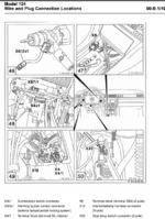
This is the extraspecial M119 specific electrical diagram. I marked everything for easy reference.
Assuming the PBU is spitting out the correct voltages, you could check fuse F15 or the PK/GN wires leading up to Fuse F15 or even perhaps that same PK/GN wire leading up the contact 15X in the ignition switch (S2/1).

Also check ground point W1 which is the main ground behind the instrument cluster!!!
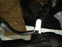
1635552273312.png

1635552640561.png
 
@Jlaa That's a great explanation and schematic. I'm thinking the same as you -- it's a flaky power supply. I'll have to check this out tonight and see what can be done. If I need to get 12v from somewhere else the I may just do that rather tear the car apart looking for the problem.

Now that I think about this, I had a similar problem with my other car, but there was no voltage between the black and red terminals at all, so I tapped off the line that had the 30A blower strip fuse and got it to work that way.
 
For grins... see if there is any difference if the ignition switch/key is turned back slightly. On my 1987 300D, I had an intermittent no-fan issue that ended up being a worn electrical ignition switch. New switch cured the problem. Finally figured out that with the engine running, if I twisted the key CCW slightly, the fan would come to life... new switch fixed it.

:klink:
 
For grins... see if there is any difference if the ignition switch/key is turned back slightly. On my 1987 300D, I had an intermittent no-fan issue that ended up being a worn electrical ignition switch. New switch cured the problem. Finally figured out that with the engine running, if I twisted the key CCW slightly, the fan would come to life... new switch fixed it.
Wouldn't it just be *rich* if it was contact 15X in the ignition switch being flaky?!?!?
 
Wouldn't it just be *rich* if it was contact 15X in the ignition switch being flaky?!?!?
I will say, this drove me BATTY in the late 90's... early in my 124 ownership journey. Took me an embarrassingly long time to figure it out. A clue was that shutting off the engine & re-starting would sometimes fix the no-fan issue.

:doof:
 
@emerydc8

What is the voltage drop across red and blue WITH the blower connected, for all three pbu settings (lo med auto)?

If the the voltage drop is zero for all three settings, can you check any of the upstream connections for red? For instance that junction with the dotted line box AFTER the fuse where it goes from bk/gn to red?
There is no voltage drop because there's no voltage coming out of the red and blue regulator output wires. I also noticed (by accident) that although there is 12v from the black and red behind the brake booster it's not "acting" like 12v when the two wires are touched together (accidentally). They barely sparked.

I'm looking at the black three-pronged receptacle mounted on the firewall and wondering whether I should try to pry that up and check the wires going to it. It seems to be held in with some sort of spring clip. Before I do that, I'll pull the instrument cluster like you suggested and see if I can trace the power source from there to that three-pronged receptacle (if I can see anything back there).
Sounds like you are making progress.
You may wish to keep in mind that once you get behind the firewall (behind the instrument cluster), Red turns into BK/GN and Black turns into BRN.

One thing you could try before you pull the instrument cluster is to test, with your multimeter, the voltage between Red@the-firewall and some arbitrary metal bolt that is grounded to the chassis.

You could also test continuity with your multimeter between Black@the-firewall and some arbitrary metal bolt that is grounded to the chassis. In this manner, you MIGHT be able to deduce if it is a +12v issue that you are dealing with or a ground issue that you are dealing with.
 
The voltage between red at the firewall and ground is 12v. There is continuity between black at the firewall and ground (0 resistance).
 
The voltage between red at the firewall and ground is 12v. There is continuity between black at the firewall and ground (0 resistance)

Hmm. Still your comment

I also noticed (by accident) that although there is 12v from the black and red behind the brake booster it's not "acting" like 12v when the two wires are touched together (accidentally). They barely sparked.
is so strange .......
 
I've never seen a case where 12v is not really 12v. Like you say -- just the potential to produce 12v.
 
I've never seen a case where 12v is not really 12v. Like you say -- just the potential to produce 12v.
Just for giggles before you pull the instrument cluster, the fuse is OK right? I know you pulled it and checked it ----- what if you just replaced it?
 
BTW This is likely not the issue, but do both X4/1 and X4/10 look ok? These are all upstream of F15 and upstream of 15X on the ignition switch.
 

Attachments

  • Screen Shot 2021-10-29 at 9.32.50 PM.png
    Screen Shot 2021-10-29 at 9.32.50 PM.png
    517.4 KB · Views: 8
  • Screen Shot 2021-10-29 at 9.31.05 PM.png
    Screen Shot 2021-10-29 at 9.31.05 PM.png
    936.4 KB · Views: 8
Yes. I tried Dave's suggestion earlier with the regulator plugged into the motor and cycling the key on and off but no help.

From behind the cluster, I am not able to see the wires leading to the receptacle at the firewall because they are being blocked by the metal structure. Any idea what this thing is, circled in red? Or why the plug circled in green is not plugged in to anything?
 

Attachments

  • Behind Cluster.jpg
    Behind Cluster.jpg
    2.8 MB · Views: 12
Yes. I tried Dave's suggestion earlier with the regulator plugged into the motor and cycling the key on and off but no help.

From behind the cluster, I am not able to see the wires leading to the receptacle at the firewall because they are being blocked by the metal structure. Any idea what this thing is, circled in red? Or why the plug circled in green is not plugged in to anything?
Dang that is so hard to tell. Can you get a few more pics / diff angles / zoom out / in? What os the color of the wire connected to your red circle?

I tried to brighten up the image. [500Eboard] Behind Cluster.jpeg

Note that the green circled wire seems to be BK/GN-----

1635569166438.png

And note that BK/GN leads to red@the-firewall. Out of curiosity, using the multimeter, does the green circled connector and the red@the-firewall connector show continuity on the multimeter?
 
It's green and black wires on the bottom of the pic (the green is hard to see) and then brown and blue wires coming out toward the top. Whatever this component is, it is wrapped in a foam sleeve, which I slid up so you can see it. I'll have to pull the knee panel down to check X4/1.
 

Attachments

  • Mystery Component.jpg
    Mystery Component.jpg
    4.2 MB · Views: 3
Dang that is so hard to tell. Can you get a few more pics / diff angles / zoom out / in? What os the color of the wire connected to your red circle?

And note that BK/GN leads to red@the-firewall. Out of curiosity, using the multimeter, does the green circled connector and the red@the-firewall connector show continuity on the multimeter?
Yes, it is black and green. I'll check for continuity.
 
It's green and black wires on the bottom of the pic (the green is hard to see) and then brown and blue wires coming out toward the top. Whatever this component is, it is wrapped in a foam sleeve, which I slid up so you can see it. I'll have to pull the knee panel down to check X4/1.
Ah. This is the thing that caught my attention because you said this is not connected to anything and this has a GN/BK wire and GN/BK connects to red @ the firewall!!!

1635570370419.png


1635570385096.png
 
I just checked for continuity between either pole of that unplugged receptacle (lower left) and the red at the firewall. There is no continuity. Also, the mystery component (right) is just a plug of some sort. I unplugged it and checked for continuity between all terminals of that plug and the red at the firewall and there isn't any continuity there either.
 

Attachments

  • Plug.jpg
    Plug.jpg
    26.9 KB · Views: 4
Ah. This is the thing that caught my attention because you said this is not connected to anything and this has a GN/BK wire and GN/BK connects to red @ the firewall!!!
These wires in the pic above are either green or black -- not GN/BK. Both just happen to be a green wire and a black wire molded togther to make one unit. I'm thinking that neither of the wires in my pic is associated with the red at the firewall.

[EDIT]: In the end, I decided to grab 12v from the blower fuse and run it to the red terminal of the regulator. I'm not sure why both cars have had the same issue with red at the firewall not producing any or the correct current, but the car has been in the garage for four weeks and it was time to get it fixed. It's all together now and working fine. Thanks to @Jlaa @gsxr and @kiev for the help on this.
 
Last edited:
The connectors circled in red/green in the above photos are for the driver-side dash speaker. The red circle / round connector is for the primary speaker voice coil, the green circle / square connector is for the cell phone voice coil. While the colors happen to be the same, they are MUCH smaller wire size and totally unrelated. The pink/green 4.0mm/2 feed from the ignition switch is a single wire running out the primary fuse box, to the external fuse holder - it doesn't route left of the instrument cluster.

It sounds like there is an issue at fuse F15, if Jon was able to make the blower work by sourcing +12v from F15, but there's no power at X64. If normal power is at F15, that also means S2/1 (ignition switch) is OK.

Jon, make sure you sourced from the black/green side of F15, not the pink/green!

:shocking:

1635603997835.png
 
I tapped off downstream of the fuse, if that's what you mean. That would be the side furthest aft, toward the firewall.
 
I must admit that I enjoy reading this thread, because there is so much valuable knowledge here. However, this made feel kind of guilty, because all this comes on emerydc8's expense. There is not too much I could help, but I'll share with a simple helper tool, which one of those good old times electrician advised me to do. It consists of a bulb socket, a 21W bulb (the one which goes for example into blinkers) and a few wires, which I can connect to. One ends with crocodile clip, two with bolts taken out of one of connectors (got for free from junkyard). I found the one which has two ends: male and female in one (on photos connected to blue and brown wires). That way I may use on male and female sockets.

The reason to use it instead of (or together with) voltmeter is, as Jlaa pointed out in one of previous posts, that voltmeter shows you just the potential, but that does not include power consumption. That's quite possible that voltmeter will show you 12V, but the bulb will be hardly lit. That helps you find the weak point.

IMG_1563.jpg IMG_1566.jpg IMG_1565.jpg

I suppose that after all this you're just in a mode to solve this problem as soon as possible, but something to consider for the future. I keep the fingers crossed!
 
@Vinnie That is an excellent tool and one which I will built today, since I'm finished with the hack job on my blower regulator! I'm still puzzled by the concept of seeing 12v on the meter, but not really 12v. I didn't think that was possible. I do have a 12v test light, but I never thought to use it. Plus, it doesn't have the pin bushing like yours. If it wasn't so difficult to get to the firewall receptacle with everything back together, I would check to see if the red terminal illuminates the light in this tool.
 

Attachments

  • Test Light.jpg
    Test Light.jpg
    5.2 MB · Views: 3
@emerydc8 - glad that you finally got it done! As for the light test tool which you have: it might work, but it might not - it depends on the bulb, which the tool has. Many of those have some small, low power bulbs, and in such case your observation may be the same, as what voltmeter shows. We need something, what consumes more power, that's why 21W bulb (well - that's still might not be enough in same cases, but generally should work).

If voltmeter shows 12 V, then there is 12 V there. But voltmeter does not know what power does you endpoint need (or, in other words what current it needs). Power = Voltage * Current. Let's say you have a weak connection point (corroded, etc.), you can image that it's a pipe with a very small diameter - that will allow you to power for example a 2W bulb and nothing more. So, if this was normally a circuit for 2W bulb then everything would be fine! However to power for example a 50 W motor you would need a pipe with much larger diameter, but the corroded point does not allow for more electrons to flow. The meter shows 12 V, but the motor won't move at all, because there is not enough current. That's the whole mystery :) Been there experienced that - that's why I know now. Initially I was thinking exactly like you.
 
This thread never seems to end. So today, my blower fan completely stopped working. I checked for voltage at the 30A strip fuse next to the fuse box and there's nothing. Then I got to wondering if I even had power to my radiator cooling fans. With the engine running, I pulled the coolant temp sensor on the intake manifold hoping the fans would activate in high. Nothing! Does anyone have a schematic handy so I can try to trace this problem? I am wondering if this really is a bad ignition switch as some have suggested. :banghead:
 
This thread never seems to end. So today, my blower fan completely stopped working. I checked for voltage at the 30A strip fuse next to the fuse box and there's nothing. Then I got to wondering if I even had power to my radiator cooling fans. With the engine running, I pulled the coolant temp sensor on the intake manifold hoping the fans would activate in high. Nothing! Does anyone have a schematic handy so I can try to trace this problem? I am wondering if this really is a bad ignition switch as some have suggested. :banghead:
Oh dear.


The diagrams I posted were from 83-6.00. Good luck!
 
Jon, the schematics for the M119 cars are separate, at @Jlaa's link above scroll down to "Index (Model Year 1993 thru 1995)" and search for the appropriate PDF.

:detective:
 
I am wondering if this really is a bad ignition switch as some have suggested. :banghead:

Out of curiosity ( since you have had the same problem now on two E500Es) I am just thinking what could be the same across two cars ….. and I wonder how big/heavy/small/light your keychain looks like….
 
Out of curiosity ( since you have had the same problem now on two E500Es) I am just thinking what could be the same across two cars ….. and I wonder how big/heavy/small/light your keychain looks like….
I haven't replaced an ignition switch on a W124 since 1997. Aside from the switch, is there anything else I should change while I'm in there? Any other parts to order?
 

Attachments

  • IMG_20211113_1714212.jpg
    IMG_20211113_1714212.jpg
    1.3 MB · Views: 21
I haven't replaced an ignition switch on a W124 since 1997. Aside from the switch, is there anything else I should change while I'm in there? Any other parts to order?

Ohhhhh what kinda GM motor is that? Vortec 4.3L? Buick 3800? L98 v8? I forgot about the two round/square key dealios!

Anyways that looks like a pretty heavy keychain, at least by my skinny-jean standards. 😂 Wonder what other folks’ keychains look like.
 
That's hilarious. Only on this forum would someone be able to identify the brand and type engine by looking at a picture of the tach and keys! Good guess -- It's an L98. I've only put about 500 miles per year on it for the past decade, but I've been driving it more since dealing with the electrical problems on the Mercedes. There are very few days that I drive it that I don't get a compliment or a thumbs up on the car. I drove this off the lot in May 1992. Somewhere along the line it went from being a ho-hum domestic to a semi-classic.
 

Attachments

  • Z28 Window Sticker.jpeg
    Z28 Window Sticker.jpeg
    1.7 MB · Views: 24
  • 1992 Z28 Camaro.jpg
    1992 Z28 Camaro.jpg
    2.2 MB · Views: 24
  • Z28 Paxton Blower.jpg
    Z28 Paxton Blower.jpg
    1.8 MB · Views: 23
I think this issue is finally solved -- It was a bad ignition switch! After removing the old switch I could hear something loose inside. Sure enough one of the tabs had broken off that runs to pin 15X. It looks like metal fatigue failure. With the new switch installed. I now have power to the 30A strip fuse powering my blower fans. I ordered an OEM switch from AutohausAZ (202 545 01 04) for $38 and had them Priority Mail it. I noticed the new switch has the MB logo ground off. There was also a bit of difference on the inside tab (pic) but apparently it doesn't matter.

REPLACING IGNITION SWITCH

I was a bit worried about changing the switch since it had been so long. I reviewed the WIS under the Steering section 46-8010 (that took me an hour to find!). Lots of notes about things that are hard to visualize until you're actually looking at the real thing.

The first thing I did was disconnect the negative battery terminal in the trunk. I didn't want to listen to the buzzer the whole time and the driver's door has to be open. Then, I removed the three-piece connected plastic trim that runs across the top of the steering wheel, including headlight switch and large nut (careful with the integral light for the headlight switch when you remove the trim above it). Then I removed the lower knee panel to get to the switch. Using the home-made 2mm diameter ignition lock tool was simple enough -- turn the key to position #1, insert tool and pull out.

There are two electrical plugs in front that are easy to pull off. Also, there's a cable on the right side that runs from the gear shift to the ignition called a parking lock interlock. I easily unscrewed the knurled thumb-nut that attaches the cable. The rubber plug that goes into the ignition switch from behind wouldn't come off as there was no room. I ended up loosening the jacket tube clamp (Allen bolt) and pushed in on the locking pin with a small screwdriver (pic). This allowed me to rotate the entire assembly down enough to get to the plug and pull it off.

The ignition switch is held on with three small Phillips screws that are inside the switch where the pins are located. I tried multiple screwdrivers and even a few socket-driven drivers but one started to strip and I just couldn't get the leverage I needed.. I decided that since I had gone this far, I might as well take the whole assembly out. Once out the three screws came right out and I was able to swap out the switch. There is a detent on the switch housing for mating it up to the assembly that makes that part idiot-proof.

There are multiple installation notes about the correct position of the ignition switch for re-installation. My new switch was not factory-set to the correct position, so I had to move it there with a small screwdriver in the rectangular slot as per the notes. When set correctly, this allows the locking pin to retract enough to slide the assembly back into the jacket tube. You'll know if it's not set correctly because the assembly will not fit back into the jacket tube (ask me how I know).

I decided to install the ignition tumbler before tightening everything down so I could test the steering lock mechanism, the general operation of the key and movement out of park with the shift lever. There was a note that states that "the parking lock valve must be pushed back through the bore for the wire cable in order to remove the ignition key." I don't really know exactly what that means but all I did was screw the cable back onto the assembly only going hand-tight on the knurled thumb-nut. Everything seemed to check out okay so I tightened the jacket tube clamp with the Allen bolt, plugged in the electrical connections and closed it up.

One final note, there are two half-moon spring-loaded clips around the lock assembly that hold the black cover that surrounds the key hole. If you are not careful, they will fall off and you will need to reinstall them. See the last pic for where these clips insert (one half-moon clip on each side of the cylinder).

Thanks to everyone who helped me on this blower motor/regulator saga. I'm going to order another ignition switch and do my other car.
 

Attachments

  • New Top Old Bottom.jpg
    New Top Old Bottom.jpg
    1.4 MB · Views: 29
  • Jacket Tube Clamp & Locking Pin.jpg
    Jacket Tube Clamp & Locking Pin.jpg
    1.3 MB · Views: 25
  • Pin 15X Broken.jpg
    Pin 15X Broken.jpg
    1.4 MB · Views: 28
  • Black Cover Retaining Clip Slots.jpg
    Black Cover Retaining Clip Slots.jpg
    3.5 MB · Views: 19
Last edited:
Glad you found it. Yes, it's actually a good idea if you order TWO of them, and have a spare on hand. They are cheap enough, and if you have enough cars of the era you will eventually need a spare/new switch again. I've got two new ones in my stockpile, as all of my cars take the same switch. Also not a bad item to grab from a wrecking yard, used, if you have the patience to wrestle it out.

Same with headlight switches.
 
The first thing I did was disconnect the negative battery terminal in the trunk. I didn't want to listen to the buzzer the whole time and the driver's door has to be open.
It's IMPERATIVE that you retrofit the gray switches to your front doors, in addition to the trunk, for just this very situation.
96196307-A32E-4E24-A1FB-EB5424388097.jpeg

Prepare to feel the wrath of @DerFuror for this omission.
 
Jon, thanks for the update - really happy you were able to identify the root cause of the problem, and fix it. Crazy that you had this on two different cars, while so far we haven't heard of any other ignition switch failures (yet). I have a feeling this may become more common as the cars pass the 30-year mark, and/or rack up more miles.

:oldster:
 
Just checked my spare parts. I ordered these three years ago when they were all the rave. I must have installed two of them because I bought five.
 

Attachments

  • Door Switches.jpg
    Door Switches.jpg
    4.7 MB · Views: 13
On these ignition switches and head light switches, these suckers are used often and control a lot of voltage. As GVZ said, get spares. If you find that your tumbler (assuming someone didn't replace it yet at purchase) is sloppy you should indeed change the tumbler and the switch. It is a once an ownership issue / repair. Everything electrical on the vehicles are handled by both the ignition and headlight switches.
 
Just checked my spare parts. I ordered these three years ago when they were all the rave. I must have installed two of them because I bought five.
Did you install them yet?

You sure missed out on a lot of ladies' attention over the past years by not installing them.
 
Did you install them yet?

You sure missed out on a lot of ladies' attention over the past years by not installing them.
I installed them in the driver's side door and trunk using your excellent HOW-TO. So far no comments, but I'll leave the door wide open while getting gas next time and see how that works. Maybe I need the mileage sticker above the switch, ike yours
 
Is there a good way to determine if it's ignition switch or regulator?

My 92 car has 250k mi which certainly makes me suspect the ignition switch (headlight switch failed at 225k mi). I never heard any distinctive motor squeaking but it went dead one day (motor was replaced in 02 at 136k mi). Last night I was pullling the car out and w ignition in the on position the fan came on at full speed, but low didn't work and auto was sketchy. I pushed some different mode buttons and couldn't get it to come on.

Today I checked the voltages across the black and yellow pins on the three pin connector near the brake booster. 1.2V low, 2.2 Auto, 7.5 on high. Lowish, but totally within range below. I replaced the 30A fuse and cleaned the contacts, no difference.

Just wondering what to replace next - the fan not working in low but fine in high makes me think regulator, but reading this post left me a bit confused - seems like the tumbler [ignition switch] can cause Low/Hi irregularities like this too. The tumbler [ignition switch] is only $32 on RevParts.


1687915993839.png
 
Last edited by a moderator:
... Last night I was pullling the car out and w ignition in the on position the fan came on at full speed, but low didn't work and auto was sketchy. I pushed some different mode buttons and couldn't get it to come on.
Did you mean that you pressed the low-speed button and the fan remained on high speed? Because I've never heard of that failure mode before.


Today I checked the voltages across the black and yellow pins on the three pin connector near the brake booster. 1.2V low, 2.2 Auto, 7.5 on high. Lowish, but totally within range below. I replaced the 30A fuse and cleaned the contacts, no difference.
Pushbutton signal is accurate, per your measurements.


Just wondering what to replace next - the fan not working in low but fine in high makes me think regulator, but reading this post left me a bit confused - seems like the tumbler [ignition switch] can cause Low/Hi irregularities like this too. The tumbler [ignition switch] is only $32 on RevParts.
A failed regulator typically either results in a single fixed speed regardless of input signal, or variable between low and medium (will not go to high speed).

A failing ignition switch typically causes the fan to either run, or not run at all. It shouldn't cause speed irregularities.

I don't recall Low/Hi irregularities in this thread, or at least I couldn't find that skimming back through the thread?


:detective:
 

Who has viewed this thread (Total: 4) View details

Who has watched this thread (Total: 3) View details

Back
Top