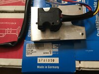
I just installed a new Kaehler (KAE) blower motor regulator, after the one I had installed just six months ago went bad. The motor was also installed six months ago and is from the dealer. At first the low speed stopped working, so I was running in auto and high, then the auto and high stopped working -- typical symptoms of a failing regulator that most of us have seen before.
After installing this second regulator tonight, I decided to leave the blower housing open to test it. It worked fine in low, but as soon as I selected auto it stopped working. Then it wouldn't work in any position. When I briefly applied 12v directly to the motor (bypassed the regulator), it ran at a fairly high speed., so the motor seems to be working.
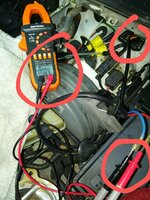
I measured the voltage coming out of the terminal where the regulator plugs in, behind the brake booster. Of course, voltage between black and red is always battery voltage (approx. 12.3v). Voltages between black and yellow are 1.2v in low, 4.5v in auto and 10v in high., so I think the voltage up to that point is correct. But when I check the voltage coming out of the regulator, it is .7v in low, 250mv in auto (variable) and 150mv in high (variable). I swapped out the push button control selector with a known good unit and got roughly the same voltage readings. The 30A strip fuse is fine. I took it out and held it in my hand.
If I were starting from a clean slate, I would think the blower regulator is bad. But this is the second regulator and it did work tonight for about a minute on low before I selected auto and it completely went kaput. Could something else be causing the regulators to fail, or is it likely just bad quality regulators? It's hard to believe it was bad right out of the box. I'm not sure where to go on this one, other than to try another regulator. My concern is that if the six-month-old factory motor is intermittently bad, am I zapping regulators with it? How else can I reasonably test the motor, outside of just applying 12 volts to it?
After installing this second regulator tonight, I decided to leave the blower housing open to test it. It worked fine in low, but as soon as I selected auto it stopped working. Then it wouldn't work in any position. When I briefly applied 12v directly to the motor (bypassed the regulator), it ran at a fairly high speed., so the motor seems to be working.
I measured the voltage coming out of the terminal where the regulator plugs in, behind the brake booster. Of course, voltage between black and red is always battery voltage (approx. 12.3v). Voltages between black and yellow are 1.2v in low, 4.5v in auto and 10v in high., so I think the voltage up to that point is correct. But when I check the voltage coming out of the regulator, it is .7v in low, 250mv in auto (variable) and 150mv in high (variable). I swapped out the push button control selector with a known good unit and got roughly the same voltage readings. The 30A strip fuse is fine. I took it out and held it in my hand.
If I were starting from a clean slate, I would think the blower regulator is bad. But this is the second regulator and it did work tonight for about a minute on low before I selected auto and it completely went kaput. Could something else be causing the regulators to fail, or is it likely just bad quality regulators? It's hard to believe it was bad right out of the box. I'm not sure where to go on this one, other than to try another regulator. My concern is that if the six-month-old factory motor is intermittently bad, am I zapping regulators with it? How else can I reasonably test the motor, outside of just applying 12 volts to it?
Last edited: