• Hi Guest !

    Welcome to the 500Eboard forum.

    Since its founding in late 2008, 500Eboard has become the leading resource on the Internet for all things related to the Mercedes-Benz 500E and E500. In recent years, we have also expanded to include the 400E and E420 models, which are directly related to the 500E/E500.

    We invite you to browse and take advantage of the information and resources here on the site. If you find helpful information, please register for full membership, and you'll find even more resources available. Feel free to ask questions, and make liberal use of the "Search" function to find answers.

    We hope you will become an active contributor to the community!

    Sincerely,
    500Eboard Management

Opening Up a 722.3 Transmission

Seangbadee

E500E Guru
Member
Before I dive into the story, a quick disclaimer: This is not a how-to guide. I’m not a professional mechanic or expert—just a curious hobbyist and adventurer sharing my personal experience. Everything I describe here is simply what I did, and discovered, not what you should do. I’m putting it out there in hopes of learning from others, sparking conversation, and maybe even getting a little guidance along the way.

In pursuit of the proverbial “golden fleece”, I decided it was time to dive into the transmission on my 1995 E320. The car, powered by the M104 engine, has 150,000 original miles and is equipped with the 722.369 transmission. As part of the process, I’m also planning to make the switch to synthetic transmission fluid. I figured it was time to replace some seals and get a better sense of the internal condition.

The transmission showed some early signs of age—a slight delay when engaging reverse and a mild clunk when shifting from reverse to drive. However, it never flared or slipped at any point. Basically everything appeared okay except for the reverse issue.
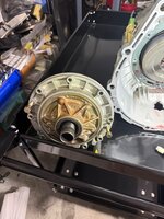
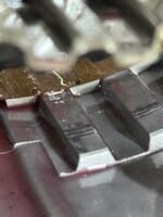
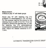
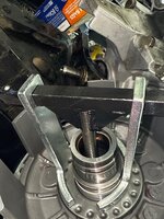
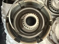
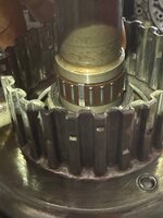
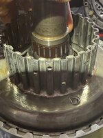
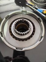
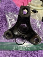
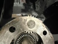
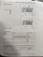
I removed the bolts for the front pump and on the surface, it checked out fine—no visible scoring or wear that raised alarms. I then turned my attention to the K1 clutch, and then things took a turn. Once I removed it from the case, I could hear the telltale rattle—a clear sign of excessive clearance. I checked for the clearance between the retaining ring and front steel plate and it was way in excess of 1.3mm ( see last picture). Flipping it over delivered the second shock: burnt steel plates.

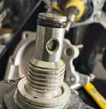
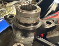
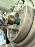
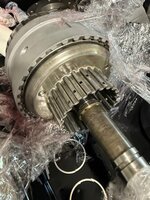
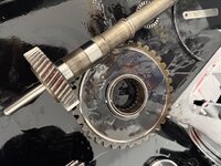
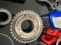
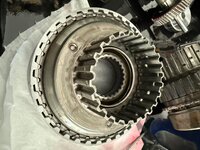
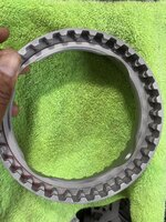
Digging deeper, I noticed signs of contact between the reverse gears and the case, suggesting some internal rubbing that shouldn’t be happening. It’s hard to say how long that’s been going on, but it’s definitely something to investigate further.
The B1 band appeared healthy. It measured in at 1.81mm, compared to the new one which measured 1.92mm.

I had already sourced new friction discs and the B1/B2 bands from Mercedes, but I held off on ordering the steel plates since I wasn’t sure what thickness I’d need.
For reference, the friction discs from the K1 clutch measured 2.1mm, compared to 2.15mm on the new MB ones. The outer K1 disc came in at 4.95mm, and the inner plates measured 4.45mm. All the steel plates in K1 had “burn” marks. As for the reverse clutch, the friction discs also measured 2.1mm, slightly below the 2.15mm thickness of new Mercedes discs. I haven’t measured the reverse steel plates yet, but the friction discs themselves appeared to be in excellent condition with minimal wear.

So, it’s back to the drawing board for now. I’ll do a bit more research before moving on to inspect K2 and B2. This detour may slow me down, but I’d rather get it right than rush things and regret it later.
 

Attachments

  • IMG_5763.jpeg
    IMG_5763.jpeg
    3.2 MB · Views: 13
  • IMG_5764.jpeg
    IMG_5764.jpeg
    3.3 MB · Views: 13
  • IMG_5784.jpeg
    IMG_5784.jpeg
    1.9 MB · Views: 12
  • IMG_5819.jpeg
    IMG_5819.jpeg
    2.1 MB · Views: 12
  • IMG_5820.jpeg
    IMG_5820.jpeg
    2.1 MB · Views: 12
  • IMG_5821.jpeg
    IMG_5821.jpeg
    2.1 MB · Views: 12
  • IMG_5822.jpeg
    IMG_5822.jpeg
    1.9 MB · Views: 12
  • IMG_5823.jpeg
    IMG_5823.jpeg
    2.5 MB · Views: 12
  • IMG_5824.jpeg
    IMG_5824.jpeg
    2.1 MB · Views: 11
  • IMG_5825.jpeg
    IMG_5825.jpeg
    2 MB · Views: 10
  • IMG_5826.jpeg
    IMG_5826.jpeg
    1.9 MB · Views: 11
  • IMG_5829.jpeg
    IMG_5829.jpeg
    673 KB · Views: 9
  • IMG_5861.jpeg
    IMG_5861.jpeg
    259.5 KB · Views: 5
Last edited:
This is great work, Sean! I'm starting my first-ever attempt at replacing frictions in the 722.3 as well. It looks like your frictions are in above-average condition. I would have expected some of your friction discs to be thinner / have more wear, as I found on some of my reverse and B1 discs. I didn't see burn marks but I'll double check. I don't plan to dig into the K2 which looks like a lot more work.

Make sure to take the front pump assembly apart to replace all the O-rings, especially the large diameter front pump O-ring which is a common leak point. This will require fabricating some tools to compress the spring plate. When re-assembling, only install 15 or 16 springs (evenly), not all 20.

@Klink, and comments on Sean's photos so far? Or other tips / tricks for us n00b's?

:klink:
 
Make sure to take the front pump assembly apart to replace all the O-rings, especially the large diameter front pump O-ring which is a common leak point. This will require fabricating some tools to compress the spring plate. When re-assembling, only install 15 or 16 springs (evenly), not all 20.
I picked up this tool from either eBay or Amazon, and it made removing the circlip and spring feel effortless—almost like child’s play.
 

Attachments

  • IMG_5831.jpeg
    IMG_5831.jpeg
    818 KB · Views: 10
  • IMG_5832.jpeg
    IMG_5832.jpeg
    875 KB · Views: 10
  • IMG_5833.jpeg
    IMG_5833.jpeg
    684.7 KB · Views: 10
  • IMG_5837.jpeg
    IMG_5837.jpeg
    996.7 KB · Views: 10
  • IMG_5835.jpeg
    IMG_5835.jpeg
    830.1 KB · Views: 10
This is great work, Sean! I'm starting my first-ever attempt at replacing frictions in the 722.3 as well. It looks like your frictions are in above-average condition. I would have expected some of your friction discs to be thinner / have more wear, as I found on some of my reverse and B1 discs. I didn't see burn marks but I'll double check. I don't plan to dig into the K2 which looks like a lot more work.

Make sure to take the front pump assembly apart to replace all the O-rings, especially the large diameter front pump O-ring which is a common leak point. This will require fabricating some tools to compress the spring plate. When re-assembling, only install 15 or 16 springs (evenly), not all 20.

@Klink, and comments on Sean's photos so far? Or other tips / tricks for us n00b's?

:klink:
I'm definitely going to dig into K2, however, that will be after I am able to complete the front pump and K1. I also intend to change the seals in the valve body.
 
I'm definitely going to dig into K2, however, that will be after I am able to complete the front pump and K1. I also intend to change the seals in the valve body.
That is an assortment of the Teflon rings (photo below). These generally do not need replacement unless they are damaged or have excess wear, which would be unusual.

I'd replace the K1 and K2 pistons & spring trains, which are the only new parts available. Let me know if you need the part numbers. The prices have gone up quite a bit on these, unfortunately. (Note - I think the M104 uses the same as M119, but it may not hurt to double-check what's in there now.)

:strawberry:

s-l1600.webp
 
That is an assortment of the Teflon rings (photo below). These generally do not need replacement unless they are damaged or have excess wear, which would be unusual.

I'd replace the K1 and K2 pistons & spring trains, which are the only new parts available. Let me know if you need the part numbers. The prices have gone up quite a bit on these, unfortunately. (Note - I think the M104 uses the same as M119, but it may not hurt to double-check what's in there now.)

:strawberry:

View attachment 218254
Yes, I do need the part numbers. Thanks Dave.
 
This is great work, Sean! I'm starting my first-ever attempt at replacing frictions in the 722.3 as well. It looks like your frictions are in above-average condition. I would have expected some of your friction discs to be thinner / have more wear, as I found on some of my reverse and B1 discs. I didn't see burn marks but I'll double check. I don't plan to dig into the K2 which looks like a lot more work.

Make sure to take the front pump assembly apart to replace all the O-rings, especially the large diameter front pump O-ring which is a common leak point. This will require fabricating some tools to compress the spring plate. When re-assembling, only install 15 or 16 springs (evenly), not all 20.

@Klink, and comments on Sean's photos so far? Or other tips / tricks for us n00b's?

:klink:
Since I found this forum, I change my transmission filter and fluid every 25,000 miles. When I got the car 6 years ago it’s was at 118,000 miles. I’ve done 3 changes since then. I used Castrol Transmax (https://a.co/d/ezuhAJ5), but then changed to Mobil D/M (https://www.rockauto.com/en/partsearch/?partnum=mobil+atf).
I have to figure out why the K1 steel plates look the way the do 🤔
Once the rebuild is successfully completed, I’ll be sticking with Red Line ATF (https://www.fcpeuro.com/products/re...MI6NTj5si3jgMV6zfUAR0W6jyVEAQYASABEgJL3_D_BwE)
 
This is great work, Sean! I'm starting my first-ever attempt at replacing frictions in the 722.3 as well. It looks like your frictions are in above-average condition. I would have expected some of your friction discs to be thinner / have more wear, as I found on some of my reverse and B1 discs. I didn't see burn marks but I'll double check. I don't plan to dig into the K2 which looks like a lot more work.

Make sure to take the front pump assembly apart to replace all the O-rings, especially the large diameter front pump O-ring which is a common leak point. This will require fabricating some tools to compress the spring plate. When re-assembling, only install 15 or 16 springs (evenly), not all 20.

@Klink, and comments on Sean's photos so far? Or other tips / tricks for us n00b's?

:klink:
Dave, quick question—why install only 15 or 16 springs out of the full 20? Just curious about the reasoning.
 
Last edited:
I spent most of the day working on the front pump, and the K1 clutch pack. From the pump, I removed the front radial seal and tapped out the bushing for the torque converter. I’ll be pressing in the new ones as soon as I source the right steel plates for the clutch pack.
With the inner and outer O-rings replaced and both Teflon rings installed, progress was steady. The Elring transmission gasket kit includes two large black o-rings—important to note: the thicker one is for the front pump, while the thinner one fits the K1 clutch pack. They appear similar at first glance, but each has a specific role and location.
While cleaning the pump gears, I realized I may have missed a critical step—I didn’t mark their position prior to disassembly. I'm now looking into the proper method to realign them during reassembly, as simply reinstalling them without reference may not be sufficient.
Moving on to the K1 clutch pack, I removed all the friction discs and steel plates, followed by the spring seat. I’ll be replacing the o-rings in this area as well. At the base of the pack is an aluminum ring held in place by a snap ring.
Although it’s not strictly required to remove the aluminum seat, I chose to take it out to inspect and replace the o-ring. I carefully pried out the snap ring, removed the seat, and replaced the thin o-ring located within the wall of the K1 clutch. This particular o-ring sits in the lower groove; the upper groove is reserved for the snap ring during reassembly.
 

Attachments

  • IMG_5852.jpeg
    IMG_5852.jpeg
    1.7 MB · Views: 7
  • IMG_5853.jpeg
    IMG_5853.jpeg
    674.2 KB · Views: 6
  • IMG_5854.jpeg
    IMG_5854.jpeg
    697.5 KB · Views: 6
  • IMG_5851.jpeg
    IMG_5851.jpeg
    1.8 MB · Views: 7
  • IMG_5849.jpeg
    IMG_5849.jpeg
    1.8 MB · Views: 6
  • IMG_5848.jpeg
    IMG_5848.jpeg
    2 MB · Views: 6
  • IMG_5847.jpeg
    IMG_5847.jpeg
    2.1 MB · Views: 6
  • IMG_5846.jpeg
    IMG_5846.jpeg
    2 MB · Views: 6
  • IMG_5850.jpeg
    IMG_5850.jpeg
    1.7 MB · Views: 7
Last edited:
Dave, quick question—why install only 15 or 16 springs out of the full 20? Just curious about the reasoning.
There's been speculation that the reverse clutches wear faster than they should, because the spring tension is too high. It takes too long for pressure to build enough to "lock" the clutch pack, and the clutches spin/wear as they are slowly engaging. Reducing the number of springs allow the clutch pack to engage more quickly, which reduces wear, and reduces engagement time.

IIRC, there had been complaints in the early 1980's of the reverse engagement being too harsh, and MB's solution (late 80's and up?) was to slow down the engagement... which resulted in the excess reverse clutch wear. Not sure if this is accurate, @Klink would know for sure.

:klink3:
 
Yes, I do need the part numbers. Thanks Dave.
K1 spring kit = 126-270-44-77, $6.50 MSRP
K1 valve kit = 126-270-03-35, $41.50 MSRP (Only use the piston, discard the springs from this kit!)
K2 valve + spring kit = 126-270-04-35, $41.50 MSRP

The above are correct for all M119 valve bodies. I think they are the same for M104.

The pistons include new Teflon seals. Photos below show all of the above parts (except the "extra" springs that you will discard). Ignore the part number shown at the top, that is ONLY the K1 spring kit, with no blue/green valves:

1752360719034.jpeg
 
@Seangbadee - Great work so far! Loving the progress and photo updates.

Still haven't dropped a transmission in a W124, but appreciate others noting their success and flow.

To the Part numbers above - Wow some of those kits have gone up in value. Was reading along and thought they were wrong due to such a large gap vs. when I bought some in Mar 2022. Below are those numbers

126-270-44-77 / $5.00
126-270-03-35 / $2.59
126-270-04-35 / $3.26
Yup, the prices went nuts a couple of years ago. These parts were stupid cheap for a long, long time. W124performance used to sell kits on eBay back then, but not anymore... nobody is going to pay $100 for some springs & pistons.

:yayo:
 
@Seangbadee - Great work so far! Loving the progress and photo updates.

Still haven't dropped a transmission in a W124, but appreciate others noting their success and flow.

To the Part numbers above - Wow some of those kits have gone up in value. Was reading along and thought they were wrong due to such a large gap vs. when I bought some in Mar 2022. Below are those numbers

126-270-44-77 / $5.00
126-270-03-35 / $2.59
126-270-04-35 / $3.26
Thanks so much for the kind words—it really means a lot. It’s taken me a few years to finally commit to tackling this project. During that time, I quietly absorbed everything I could: videos, write-ups, articles, forum threads—you name it. I wasn’t initially planning to go this far, but once the car went in for bodywork and paint, something clicked.

What really pushed me over the edge was spotting the oil leak. I knew the rear crankshaft seal had to be replaced, and without the proper tool on hand, I figured—why not just go all in, remove the seal carrier, and address the transmission while I’m here?

Most of the parts are no longer available from Mercedes, so sourcing became its own mini adventure. I picked up what I could from FCP, found some steel plates on eBay—but once I opened it up and saw the burn marks on the B1 clutch plates, I knew it was time to tear the whole transmission down.
It’s been a learning curve, but I’m in it now. This forum has been an awesome resource, and the ATSG manual is also helpful.
 

Attachments

  • IMG_5860.jpeg
    IMG_5860.jpeg
    184.8 KB · Views: 8
  • IMG_5757.jpeg
    IMG_5757.jpeg
    699.3 KB · Views: 8
K1 spring kit = 126-270-44-77, $6.50 MSRP
K1 valve kit = 126-270-03-35, $41.50 MSRP (Only use the piston, discard the springs from this kit!)
K2 valve + spring kit = 126-270-04-35, $41.50 MSRP

The above are correct for all M119 valve bodies. I think they are the same for M104.

The pistons include new Teflon seals. Photos below show all of the above parts (except the "extra" springs that you will discard). Ignore the part number shown at the top, that is ONLY the K1 spring kit, with no blue/green valves:

View attachment 218308
Dave, this is indeed very helpful. I’ll start sourcing what will hopefully be my last set of parts—though at this rate, I might qualify for a frequent buyer discount! 🤣🛠️
 
Today was a productive step forward. I finished tearing down the rest of the transmission—bringing me one step closer to placing what I hope will be the final parts order from FCP Euro and the Mercedes-Benz online store. With everything laid bare, I can now confidently finalize the list and avoid any frustrating repeat orders.

I also did some light parts hunting at Autonation Mercedes. While their pricing is solid and shipping is easy on the wallet, delivery times are painfully slow. Still, a few items made it into the cart—I’ll just have to be patient.

I removed the rear cover after taking off the 30mm nut and pulling the flange. Hiding behind the flange was a solitary washer, just waiting to vanish into oblivion—but I caught it just in time. Next, I removed the parking pawl, its spacers, and the pawl spring. I also pulled out the Y-shaped piece, which I believe connects to the speedometer assembly. This piece has a tiny o-ring that will be replaced. I inspected the speedometer drive gear and decided to replace it—fortunately, I already have a new one on hand.

Moving on to the governor, I pulled the helical gear off the driveshaft, loosened the three bolts on the left side cover,and removed the 10mm nut from the lever, making sure to note its position on the shaft. IMG_5898.jpegIMG_5899.jpegWith everything loosened, I pulled the governor and lever out, tilting the lever upward to clear the case.
Then I removed the clip on the main shaft and slid the entire assembly out through the front. That’s when I discovered a damaged needle bearing—split vertically and missing one roller (IMG 5927 and 5928). That will definitely need replacing.

With the shaft out, I turned my attention to the K2 clutch. Its initial appearance was promising, so I moved on to the B2 band. Removing this required pushing the reaction valve and its pin into the transmission to free it—this valve has its own o-ring, which will also be replaced. The B2 band, however, is toast. The friction surface is worn down to a gritty, sandpaper-like texture and shows clear signs of burning.

At last, the case is officially empty—and ready for reassembly… once the new parts arrive. Before wrapping up for the day, I decided to inspect the K2 clutch more thoroughly. I opened it up and was pleased with what I found. The front steel plate measured in at a healthy 4.48mm. The friction discs, although they looked fine on the surface, will be replaced out of caution. They measured 2.12mm, compared to 2.15mm on the new Mercedes-Benz replacements—so wear is minimal, and honestly, I’m impressed. The rear plate came in at 2.95mm, also well within spec.
I’ve seen some people go as far as drilling out the rivets to disassemble the K2 clutch even further, but I won’t be doing that. There’s no indication of internal issues, and aside from swapping in new friction discs, K2 will remain untouched.
 

Attachments

  • IMG_5877.jpeg
    IMG_5877.jpeg
    785.7 KB · Views: 8
  • IMG_5876.jpeg
    IMG_5876.jpeg
    1 MB · Views: 8
  • IMG_5867.jpeg
    IMG_5867.jpeg
    1.3 MB · Views: 8
  • IMG_5869.jpeg
    IMG_5869.jpeg
    2.2 MB · Views: 8
  • IMG_5875.jpeg
    IMG_5875.jpeg
    2.8 MB · Views: 8
  • IMG_5881.jpeg
    IMG_5881.jpeg
    717.2 KB · Views: 7
  • IMG_5880.jpeg
    IMG_5880.jpeg
    740.9 KB · Views: 7
  • IMG_5887.jpeg
    IMG_5887.jpeg
    925.6 KB · Views: 7
  • IMG_5888.jpeg
    IMG_5888.jpeg
    923.9 KB · Views: 7
  • IMG_5891.jpeg
    IMG_5891.jpeg
    584.3 KB · Views: 7
  • IMG_5893.jpeg
    IMG_5893.jpeg
    1.5 MB · Views: 7
  • IMG_5901.jpeg
    IMG_5901.jpeg
    2.5 MB · Views: 7
  • IMG_5904.jpeg
    IMG_5904.jpeg
    2.6 MB · Views: 7
  • IMG_5903.jpeg
    IMG_5903.jpeg
    1.9 MB · Views: 7
  • IMG_5907.jpeg
    IMG_5907.jpeg
    2.6 MB · Views: 8
  • IMG_5908.jpeg
    IMG_5908.jpeg
    2.3 MB · Views: 8
  • IMG_5909.jpeg
    IMG_5909.jpeg
    2.1 MB · Views: 8
  • IMG_5910.jpeg
    IMG_5910.jpeg
    1.6 MB · Views: 8
  • IMG_5912.jpeg
    IMG_5912.jpeg
    2.6 MB · Views: 9
  • IMG_5913.jpeg
    IMG_5913.jpeg
    3.2 MB · Views: 8
  • IMG_5927.jpeg
    IMG_5927.jpeg
    1.5 MB · Views: 8
  • IMG_5928.jpeg
    IMG_5928.jpeg
    1.7 MB · Views: 8
  • IMG_5924.jpeg
    IMG_5924.jpeg
    1.4 MB · Views: 9
  • IMG_5929.jpeg
    IMG_5929.jpeg
    2.9 MB · Views: 9
  • IMG_5935.jpeg
    IMG_5935.jpeg
    2.8 MB · Views: 8
  • IMG_5936.jpeg
    IMG_5936.jpeg
    991.5 KB · Views: 7
  • IMG_5937.jpeg
    IMG_5937.jpeg
    776.2 KB · Views: 8
  • IMG_5938.jpeg
    IMG_5938.jpeg
    565.4 KB · Views: 8
  • IMG_5939.jpeg
    IMG_5939.jpeg
    660.3 KB · Views: 8
  • IMG_5940.jpeg
    IMG_5940.jpeg
    780 KB · Views: 8
Last edited:
Nice work!
LB3 / reverse brake wear has absolutely nothing to do with the engagement speed nor is there ever any slipping of LB3 because the fluid pressure to it isn't even modulated. Engagement speed is throttled a little for the sake of comfort, but LB3 is always actuated with FULL working pressure. LB3 soft plates don't wear out. They shed their material in small kibbles, bits, and powder. The material is simply a little bit under-engineered for the conditions in which it exists. The conditions are mainly this: In any gear other than reverse, the LB3 plates are spinning rapidly, most of the time at engine RPM, and they are in an uncompressed state while this is going on. Because of this, they simply shed their material, which is why we find the bulk of it packed in and lined up like tiny dominoes in the transmission filter pleats.
 
@Klink,
Nice to see your still out there klink.:) I assume you are a busy man in high demand.

I’ve been following Sean’s trans rebuild mainly for information. It’s nice to hear an expert like you chime in.

Take Care
 
While working on the output shaft, it’s worth noting a small but critical detail that’s easy to overlook. If you remove the flange from the output shaft, there’s an o-ring tucked inside the flange, right in the toothed area. This o-ring plays an essential role in preventing fluid leaks and should always be replaced during reassembly. It’s included in the transmission gasket kit, but if you're sourcing it separately, the part number is 018 997 19 48.
 

Attachments

  • IMG_5975.jpeg
    IMG_5975.jpeg
    111.8 KB · Views: 7
  • IMG_5973.jpeg
    IMG_5973.jpeg
    2.5 MB · Views: 7
  • IMG_5974.jpeg
    IMG_5974.jpeg
    1.6 MB · Views: 7
  • IMG_5976.jpeg
    IMG_5976.jpeg
    1 MB · Views: 7
Today was a productive step forward. I finished tearing down the rest of the transmission—bringing me one step closer to placing what I hope will be the final parts order from FCP Euro and the Mercedes-Benz online store. With everything laid bare, I can now confidently finalize the list and avoid any frustrating repeat orders.

I also did some light parts hunting at Autonation Mercedes. While their pricing is solid and shipping is easy on the wallet, delivery times are painfully slow. Still, a few items made it into the cart—I’ll just have to be patient.

I removed the rear cover after taking off the 30mm nut and pulling the flange. Hiding behind the flange was a solitary washer, just waiting to vanish into oblivion—but I caught it just in time. Next, I removed the parking pawl, its spacers, and the pawl spring. I also pulled out the Y-shaped piece, which I believe connects to the speedometer assembly. This piece has a tiny o-ring that will be replaced. I inspected the speedometer drive gear and decided to replace it—fortunately, I already have a new one on hand.

Moving on to the governor, I pulled the helical gear off the driveshaft, loosened the three bolts on the left side cover,and removed the 10mm nut from the lever, making sure to note its position on the shaft. View attachment 218348View attachment 218349With everything loosened, I pulled the governor and lever out, tilting the lever upward to clear the case.
Then I removed the clip on the main shaft and slid the entire assembly out through the front. That’s when I discovered a damaged needle bearing—split vertically and missing one roller (IMG 5927 and 5928). That will definitely need replacing.

With the shaft out, I turned my attention to the K2 clutch. Its initial appearance was promising, so I moved on to the B2 band. Removing this required pushing the reaction valve and its pin into the transmission to free it—this valve has its own o-ring, which will also be replaced. The B2 band, however, is toast. The friction surface is worn down to a gritty, sandpaper-like texture and shows clear signs of burning.

At last, the case is officially empty—and ready for reassembly… once the new parts arrive. Before wrapping up for the day, I decided to inspect the K2 clutch more thoroughly. I opened it up and was pleased with what I found. The front steel plate measured in at a healthy 4.48mm. The friction discs, although they looked fine on the surface, will be replaced out of caution. They measured 2.12mm, compared to 2.15mm on the new Mercedes-Benz replacements—so wear is minimal, and honestly, I’m impressed. The rear plate came in at 2.95mm, also well within spec.
I’ve seen some people go as far as drilling out the rivets to disassemble the K2 clutch even further, but I won’t be doing that. There’s no indication of internal issues, and aside from swapping in new friction discs, K2 will remain untouched.
Turning attention to the radial bearing shown in IMG_5982, this is a split bearing by design, which initially gave me a moment of concern as I thought mine had cracked. On closer inspection, I realized it was missing one of the rollers, likely lost during removal. It’s a good reminder to inspect this bearing carefully during disassembly.
The split design makes it easy to install directly onto the shaft at the K2 flange. If you need to order one, the part number is 011 981 82 10
 

Attachments

  • IMG_5982.jpeg
    IMG_5982.jpeg
    922.6 KB · Views: 7
  • IMG_5981.jpeg
    IMG_5981.jpeg
    2.3 MB · Views: 7
  • IMG_5979.jpeg
    IMG_5979.jpeg
    1.8 MB · Views: 7
  • IMG_5980.jpeg
    IMG_5980.jpeg
    1.8 MB · Views: 7
Continuing from where I left off on the rebuild of my Mercedes 722.369 transmission:

After spending the better part of the previous day meticulously rebuilding the K1 and K2 clutch packs, I turned my attention to refining the clutch clearances, a task that proved more nuanced than expected. Achieving the correct clearance after reassembling the packs into their carriers was not as straightforward as I had hoped. One frequently asked question among those undertaking similar rebuilds is whether or not to press down on the clutch pack when measuring clearance with a feeler gauge. One of the manuals I’m using, sourced from w124performance.com clarifies this in Ch. 5, Section 3.1, stating that a force of 10 N should be applied when checking clutch pack clearance. I initially misunderstood this as 10 Nm, assuming it was torque-related. In reality, 10 Newtons is simply the light pressure you’d apply with a resting finger on the outer steel plate. With that in mind, I rechecked everything and was relieved to get a consistent clearance of 0.8 mm, which is comfortably within the specified range of 0.7 – 1.3 mm.

One crucial detail during the K1 assembly was the orientation of the spring plate, the innermost steel plate in the clutch stack. This plate is slightly convex, and according to the manual, it must be installed with the crown facing toward the piston. Mine had been installed the opposite way, which is a definite sign of incorrect assembly and reinforces my growing suspicion that this transmission has been tampered with before. It now seems almost certain that this is not the original unit fitted to my car. With the clutch packs finally set, I shifted focus to the planetary gear sets.

Following the manuals closely, and notes from various forums, I carefully disassembled the gear assemblies to inspect them and replace worn components. One video that proved especially helpful in understanding the process is available here: https://youtu.be/eGNElAtNENo?si=4Ssz1__Rt7uMxOCT

P.S I came across handwritten inscriptions on the inside of the planetary carrier, which leads me to believe that this transmission may have been opened up before, and may not be the original one that came with this car. What began as routine maintenance has turned into a complete teardown and overhaul.
Today, I’ll be working on reassembling the planetary gears, carefully measuring the internal clearances, and making the necessary adjustments. Once that’s complete, I’ll move on to reassembling the rest of the transmission. Slowly but surely, it’s coming back together.
 

Attachments

  • IMG_6015.jpeg
    IMG_6015.jpeg
    1.7 MB · Views: 6
  • IMG_6016.jpeg
    IMG_6016.jpeg
    917.3 KB · Views: 5
  • IMG_6017.jpeg
    IMG_6017.jpeg
    1.2 MB · Views: 5
  • IMG_6019.jpeg
    IMG_6019.jpeg
    1.1 MB · Views: 5
  • IMG_6018.jpeg
    IMG_6018.jpeg
    1.5 MB · Views: 5
  • IMG_6020.jpeg
    IMG_6020.jpeg
    1.1 MB · Views: 5
  • IMG_6021.jpeg
    IMG_6021.jpeg
    1.5 MB · Views: 6
  • IMG_6022.jpeg
    IMG_6022.jpeg
    1.2 MB · Views: 6
  • IMG_6023.jpeg
    IMG_6023.jpeg
    2.3 MB · Views: 5
Last edited:
More great info, Sean - thank you for sharing! I had been wondering how much to press on the clutch pack when measuring clearance. I had not yet researched this, so I'm grateful you found the 10N force spec in the manuals. 🙏

You can verify if the transmission in your car is original, by checking the serial number vs the datacard. If they match, it's possible the transmission had been opened up / rebuilt previously. If the numbers don't match, yep, it was replaced.

:detective:
@gsxr, I just did that. The numbers do not match. The original transmission was 722369 04 128097. This transmission is 722369 03 967710. This confirms that the transmission was replaced.
 

Attachments

  • IMG_6032.jpeg
    IMG_6032.jpeg
    639 KB · Views: 2
Last edited:
More great info, Sean - thank you for sharing! I had been wondering how much to press on the clutch pack when measuring clearance. I had not yet researched this, so I'm grateful you found the 10N force spec in the manuals. 🙏

You can verify if the transmission in your car is original, by checking the serial number vs the datacard. If they match, it's possible the transmission had been opened up / rebuilt previously. If the numbers don't match, yep, it was replaced.

:detective:
@gsxr, you’re welcome.
 

Attachments

  • IMG_6024.jpeg
    IMG_6024.jpeg
    2.7 MB · Views: 4
Before coupling the rear planetary assembly, I decided to check the clearance between the shim ring and the connecting member of the gear carrier. Well—pleasant surprise—there was no shim present at all.
The clearance measured between 0.23 mm and 0.25 mm, which is outside the acceptable range of 0.05 mm to 0.20 mm. I marked the areas where the clearances were passed the limit, then disassembled the unit to confirm whether there was actual wear on the rear surface of the disc carrier. Sure enough, once the retaining ring was removed, the shiny spots I found matched exactly with the areas I had marked—clear evidence of wear.
For the 722.3 transmission, shim rings were originally offered in three thicknesses:
  • 0.1 mm (part no. 1262721752)
  • 0.2 mm (part no. 1262721852)
  • 0.5 mm (part no. 1262721952)
Unfortunately, all of these shims are no longer available from Mercedes.
 

Attachments

  • IMG_6025.jpeg
    IMG_6025.jpeg
    1.3 MB · Views: 4
  • IMG_6027.jpeg
    IMG_6027.jpeg
    1.3 MB · Views: 4
  • IMG_6028.jpeg
    IMG_6028.jpeg
    2 MB · Views: 4
As the project continues, more issues have come to light. This morning I confirmed that the transmission in the car is not the original, raising the question of why it was replaced with fewer than 120,000 miles on the car.
During the process of changing o-rings and seals, I discovered that the o-ring on the detent pin for the B1 band was extremely brittle, indicating significant aging. After replacing it, I noticed the absence of any shims or washers on the pin. Despite careful organization during disassembly, I found no trace of them in my parts bags.
A closer inspection of the B1 piston components revealed that the aluminum pin carrier surface was unusually polished. This suggests it has been wearing down from direct contact, likely due to the missing steel washer that should have been in place to prevent such wear.
To address this, I will replace the cover and source the correct washers and shims from Mercedes-Benz, provided they are still available. I plan to continue the project next weekend, with each step offering more insight into the transmission’s overall condition.
 

Attachments

  • IMG_6034.jpeg
    IMG_6034.jpeg
    1,003.7 KB · Views: 4
  • IMG_6033.jpeg
    IMG_6033.jpeg
    548.3 KB · Views: 4
  • IMG_6035.jpeg
    IMG_6035.jpeg
    1.2 MB · Views: 4
After discovering that this isn’t the car’s original transmission, I decided to approach the rest of the rebuild with a hyper-meticulous mindset—measuring all clearances and ensuring everything is within spec using the correct parts. Thankfully, it’s a 722.369 transmission, which is exactly what I was hoping for. 😊🙏
Other than a slight fluid weep, a minor delay when shifting from Reverse to Drive, and the occasional whine, the transmission has been solid. That gives me confidence it’ll perform even better after the rebuild.
I’m installing new bands (the B2 band is a made-in-China unit—:shocking:
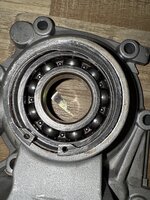
), new MB friction discs, seals, and bearings wherever possible. I’m also replacing the rear transmission cover bearing, with a MB replacement (made in Germany) 🙏
Since there isn’t much else I can do until more parts are ordered and arrive (💲💲😭
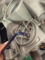
), I turned my attention to the rear cover repair. As part of that, I removed the rear cover seal to access the circlip, which holds the output shaft bearing in place.
Removing that circlip was such a challenge, but once out, I was able to gently tap the old bearing out from the underside using the exposed edge of the bearing. The original circlip measures 2.15mm thick and will be replaced with a new one. The thickness of the replacement will depend on how the bearing seats, as there must be zero clearance between the locking ring and the cylindrical roller bearing.
The circles come in 3 sizes:
2.0 mm - A0039945241
2.1 mm - A0039945341
2.2 mm - A0039945441
Since I was already in there, I swapped out the speedometer gear with a new (MB) one.
 

Attachments

  • IMG_6008.jpeg
    IMG_6008.jpeg
    2.1 MB · Views: 6
  • IMG_6040.jpeg
    IMG_6040.jpeg
    1 MB · Views: 6
  • IMG_6041.jpeg
    IMG_6041.jpeg
    998 KB · Views: 5
  • IMG_6046.jpeg
    IMG_6046.jpeg
    409.9 KB · Views: 5
  • IMG_6043.jpeg
    IMG_6043.jpeg
    941.9 KB · Views: 6
  • IMG_6042.jpeg
    IMG_6042.jpeg
    894.9 KB · Views: 6
  • IMG_6047.jpeg
    IMG_6047.jpeg
    919.9 KB · Views: 7
Last edited:
With the rear cover work still in progress and more parts yet to be ordered, I decided to make use of the downtime by turning my attention to the kickdown solenoid (0003041890), mounted at the rear of the transmission.
I pulled the solenoid out of its cradle to replace the three o-rings that seal it in place. These seals are not included in the transmission gasket kit.
Here are the part numbers for reference:
  • Tip o-ring (very small): 0019973548
  • Middle o-ring: 0089973048
  • Top o-ring: 0089973148
 

Attachments

  • IMG_6048.jpeg
    IMG_6048.jpeg
    275 KB · Views: 5
  • IMG_6049.jpeg
    IMG_6049.jpeg
    391 KB · Views: 5
Last edited:
After a relentless week of digging through dusty catalogs, chasing dead-end leads, and nearly giving up hope, I finally tracked down the elusive planetary shim for my 722.369 transmission—of all places, at Porsche. As it turns out, this Mercedes transmission pulled double duty in the 1983 Porsche 928. Who would've guessed? The moment felt less like finding a car part and more like unearthing a lost artifact—I practically heard a choir of angels singing over the parts counter. 🙌🔧🎉 Hallelujah! 😄
 

Attachments

  • IMG_6090.jpeg
    IMG_6090.jpeg
    1.4 MB · Views: 2

Who has watched this thread (Total: 2) View details

Back
Top