I recently had to troubleshoot my twin electric fans in front of the condenser, and discovered the schematic is split across pages of the factory PDF, making it nearly impossible to read. I had to monkey with the PDF to view it continuously, but couldn't print that way - I had to take a screenshot and print the image. See attached screenshot with the entire schematic in easy-to-read, easy-to-print format. Click here for the source PDF file, of which page 1 has the key to deciphering the alphanumeric component notations. Print page 1 of the PDF along with the image attached below.
Basic operation principle (124.034 and 124.036 only):
These fans run on low speed based ONLY on refrigerant pressure. When refrigerant pressure (high side) exceeds 16 bar (235 psi), the fans turn on low speed. When pressure drops below 12 bar (175 psi), the fans turn off low speed. The fans DO NOT run constantly when the AC is engaged. In cooler ambient temps, the fans may not run because pressure is low. However in higher ambient temps (say, 90F+) the fans may run continuously on low speed. This is not designed to reduce engine coolant temp, but it will help cool the engine. It's designed to keep airflow over the condenser to keep condenser pressures under control, and improve AC performance.
These fans run on high speed based ONLY on coolant temperature. A bone-stock vehicle will turn the fans on at 107°C coolant temp (approximately with the needle halfway between the unmarked line on the gauge, and 120°C. The unmarked line is 100°C). The fans will turn off at approximately 98-100°C. Some people have installed a "CoolHarness", which is a resistor that fools the system into thinking engine temp is higher than actual. The idea is to turn the fans on high speed at, say, 100C or 95C. The problem with this is twofold: first, the fans may never turn off because the perceived coolant temp is never low enough. And second, in cold ambients with the heat on and auto fan speed, the fan may start ramping up speed above "min" well before hot air is available - I found this annoying. I removed the "CoolHarness" from ally my cars. If the viscous fan clutch is working properly, there should be no need to run the electric fans on high speed all the time. Plus, they are loud and obnoxious on high speed. I know some people like this modification who live in hot climates, and if it works for you, that's great.
Basic testing:
To test low speed, locate the red pressure switch behind the driver side headlight, attached to the receiver/drier. With the engine off and ignition on, short the leads of the red switch together. This should energize the relay and the fans should run on low speed.
To test high speed, locate the 2-pin temperature sensor (B11/7) at the front of the intake manifold, near a 1-pin and round 4-pin sensor. With the engine running, or ignition on and engine off, pull the connector off the 2-pin sensor. Usually, but not always, this will turn the fans on high speed. If the fans do not run, insert a resistor of approximately 150 ohms to 250 ohms across the female sockets, to simulate a temperature above 107°C. The relay should energize and the fans should run on high speed when the resistor is inserted.
Troubleshooting & common faults / problems:
- First check is the fuse:
- Pre-facelift cars have a 30A strip fuse located outside the main fuse box, usually behind the brake booster. Don't just visually check this, unscrew and remove it. You may find it break apart. Replace if needed. Pre-facelift cars have a single, double-size relay with no additional fuses.
- Facelift cars have NO strip fuse!, Instead, they have 2 separate fused relays located in the rear half of the fuse box. Unscrew the lid and remove it, you will see 2 relays each with integrated fuse. Check / replace the fuses as needed. Low speed is blue/15A, high speed is green or orange, with 30A or 40A fuse.
- After a blown fuse, the most common fault is a broken wire at the top of the low-speed resistor, behind the driver headlight, below the ABS/ASR pump. This typically results in no low speed fan, but could cause both low and high speed to fail. Repair the wiring as needed.
- The ceramic resistor sometimes fails, or has the terminals corroded. Clean and re-use if possible. If beyond repair, buy a good used one. New are NLA.
- If the AC pressure is well above 16 bar / 235 psi and the fans are not running, but do run on low speed per the "basic test" above, the pressure switch may have failed. Replace with OE/Genuine switch, part # 004-820-68-10. The ACM-branded red switch had been reboxed OEM but I do not know if that is still the case. This requires evacuating, vacuuming, and recharging the AC system and you don't want to repeat the job when a cheap off-brand switch fails again.
- If the fans do not run on high speed at 110°C+ coolant temps, but do run on high speed per the "basic test" above, it's possible that temp sensor B11/7 has failed. Try replacing it, MB # 008-542-45-17, again buy OE only. I've never encountered one of these sensors which has failed, yet.
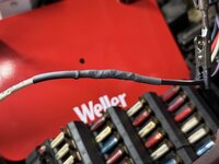
- It's possible that a wire inside the harness could fail - this happened on my car at 200kmi (see next post). I've never heard of anyone else reporting this failure.
- It's possible that a relay could fail, but I've never seen or heard of this happening (yet). The OE relays are quite robust.


")


