• Hi Guest !

    Welcome to the 500Eboard forum.

    Since its founding in late 2008, 500Eboard has become the leading resource on the Internet for all things related to the Mercedes-Benz 500E and E500. In recent years, we have also expanded to include the 400E and E420 models, which are directly related to the 500E/E500.

    We invite you to browse and take advantage of the information and resources here on the site. If you find helpful information, please register for full membership, and you'll find even more resources available. Feel free to ask questions, and make liberal use of the "Search" function to find answers.

    We hope you will become an active contributor to the community!

    Sincerely,
    500Eboard Management

w124 Integrated Cellular Telephone - Service & Parts Literature S 2495 000 + Wiring Diagram

Jlaa

OG ⏰ 500E
Staff member
I couldn't find literature related to the operation of the integrated cellular telephone anywhere on the Internet. I wanted the product to provide the quality & performance which I have come to know and expect. I was fortunate enough to discover that I had a hardcopy of this manual with my books - therefore I have scanned a copy of this manual for archival purposes and posted it here. It is my hope that you can take a few minutes to carefully read this guide so that you may maximize your enjoyment from your telephone. 🤣🤣

EDIT --- I just realized Gerry sent me this manual 3 years ago. 🤦🏻‍♂️

I've also included a related cut of the wiring diagram related to the integrated cellular telephone. Note that there is a portion where there is a solder-splice in the bus cable from the overhead control unit to the transmitter/receiver unit in the trunk. If anyone knows what this solder/splice is for, or has the dealer-installation documents, it would be nice to post those for posterity as well. I don't expect anyone really to have that though.

I searched through w124performance.com and well as w124-zone.com and came up empty.

Cheers!

Cellular Telephone Wiring.png
 

Attachments

Last edited:
Jlaa, that schematic does exist in the FSM, but it's not easy to find. It's in the ETM (Electrical Troubleshooting Manual), PDF page 102 of 277.

Most of the electrical stuff is hard to locate, and it's worse for items which are unique to 1994-95 USA model years, as those are not in the primary ETM... they are separate PDF files, not indexed via HTML until the latest Nervig update, which is not yet on W124performance or w124-zone.

However, the Emperor has the latest Nervig index on 500Eboard... see Group 24:

:clarkvader:
Sorry, right, I got the wiring schematic from pg 102 of the ETM. What I meant to say was that I was unable to find the operation manual for the cellular telephone online anywhere, and so I have posted the pdf here. BTW --- the overhead control panel is actually much more sophisticated than I thought! All those M1 / M2 and D buttons were multi-function, depending on the # of button presses. As well, there seems to have been some early mapping of spoken phrases like "Residence," "Office," "Emergency," "Dealer," "Roadside Assistance," and "Personal." to actual phone numbers!!!!! Seems pretty sophisticated for 1992/1993!
 
OH, now I understand... I saw the schematic and didn't realize the link below was different. :doh: :doof:

I think W124performance may have this uploaded shortly.

:matrix:
 
Nice piece of equipment. I wish my car came equipped with this kit. European cars were fitted with something different, Nokia perhaps?
 
Nice piece of equipment. I wish my car came equipped with this kit. European cars were fitted with something different, Nokia perhaps?

The reason why I am looking into this is that I wish to use the existing overhead control panel to control my modern iphone, circa 2020. My plan is to repurpose the buttons in the Mercedes control panel to activate some switches that go into the IO ports of a Raspberry Pi.
I will have to manufacture a new PCB in order to interface with the buttons in the overhead control panel, as well as to control the lighting in the overhead control panel.

The reason why I am using a Raspberry Pi is that the Pi would act as a handsfree bluetooth "host" --- I would connect a speaker to the Pi, and tie in the microphone opening in the overhead panel (see at the left) and the Pi would allow me to place handsfree calls.

I will start a new thread on this as I go. I have made some progress with the Pi and the software stack to connect the pi with my phone. The most challenging part for me will be the mechanical engineering to make a new PCB that has switches that the original overhead control panels can engage with.

IMG_8261.jpeg
 
Well, I went that route a year ago but never shared any pics or info... :peep:
I use the overhead panel to control the double remote for garage door and property gate. SEND button controls the hands free system (modern bluetooth unit), I also replaced the built-in mic with the new one, however I think that the Motorola mic can be used with any hands-free system.
 
Well, I went that route a year ago but never shared any pics or info...
I use the overhead panel to control the double remote for garage door and property gate. SEND button controls the hands free system (modern bluetooth unit), I also replaced the built-in mic with the new one, however I think that the Motorola mic can be used with any hands-free system.
Nice! Did you backlight the buttons as well and reuse the “no svc,” “roam,” “in svc,“ and ”dot” Lights to display status?
 
I like the idea for the garage-door opener. What was required for that mod?

:wahoo:
 
I like the idea for the garage-door opener. What was required for that mod?

:wahoo:
Right! @darek_u would it be possible to see how you mechanically reused the old motorola buttons? The original “switches” are just printed pads on the motorola pcb.

Aside from solving that mechanical puzzle, @gsxr, you could just hack an existing GDO remote and tie it in....
 
Last edited:
I like the idea for the garage-door opener. What was required for that mod?

Most Homelink modules use momentary circuit board mounted buttons. If the factory cell phone pad operated in a similar fashion, then it would be simple to just solder some wire onto the circuit board and route it to the Homelink. A tap into the Homelink LED could also be routed back to the illumination panel of the Motorola, which in theory would allow it to light when you pressed one of the buttons.

Of course, a simpler solution would be to just upgrade the OEM rear view mirror with one that has integrated Homelink ;-)
 

Attachments

  • elec169_homelink_pcb.jpg
    elec169_homelink_pcb.jpg
    171.2 KB · Views: 7
Most Homelink modules use momentary circuit board mounted buttons. If the factory cell phone pad operated in a similar fashion, then it would be simple to just solder some wire onto the circuit board and route it to the Homelink.

The factory overhead control panel is not so simple. Carbon painted rubber buttons press directly against the PCB, closing the circuit. I tried measuring the resistance --- not so simple as a simple switch. With the PCB off, I got varying values in the thousands of ohms depending if the rubber buttons were pressed or not. I suspect the Motorola PCB needs to be powered.

That's why I'm considering creating my own PCB with switches like you show, @2phast, behind the rubber carbon-printed motorola buttons.

That's why I'm also interested in what @darek_u did....


IMG_8268.jpeg IMG_8269.jpeg
 
I'll write few word later on, no time now... Long story short I soldered a remote control wires to the panel, something similar to what 2phast is saying in post above. Hands free is a different story

.20181003_072147.jpg
 
Last edited:
@darek_u -- Now you handed @Jlaa his latest "Squirrel!" project. He will be on a mission and will not be deterred until that mobular phone control button panel is fully running hand-free phone and garage door functionality. I'm sure the Raspberry Pi will now be used to run a home theater inside the car or semi-autonomous driving control.
 
@darek_u -- Now you handed @Jlaa his latest "Squirrel!" project. He will be on a mission and will not be deterred until that mobular phone control button panel is fully running hand-free phone and garage door functionality. I'm sure the Raspberry Pi will now be used to run a home theater inside the car or semi-autonomous driving control.
Pretty much. 🤣. I don’t use garage door remotes though - I prefer to get out of the car. @darek_u Thanks - when you have time to type, I would like to understand how the button w contacts printed on the pcb works.
 
I don’t use garage door remotes though - I prefer to get out of the car.

Is this for security reasons?
My brother is the same. He stores some very valuable items in his garage, aside from his car collection and has always been weary of scanners for garage remotes. It's an inconvenience, but has trained his kids to be his "remote" and that has worked very well.
 
Is this for security reasons?
My brother is the same. He stores some very valuable items in his garage, aside from his car collection and has always been weary of scanners for garage remotes. It's an inconvenience, but has trained his kids to be his "remote" and that has worked very well.
Yes, you got it. I am wary of scanners!
 
OK, here is some info. Firstly - my apologies but I'm not a "how to" kind of guy... I just do something and forget it, I don't make any notes etc., just a few photos. Shame on me, I know :thumbsdown: Anyway, here is what I remember.
I think I'll start from power. My panel is powered through purple (+12V) and light blue wire (ground for electronics), be aware that yours could have different colors in the 8 wire cable with RJ45 connector. Applying +12V will lit up all buttons and green power LED. In fact it is all what you need if you want to wire in a remote control for gate etc. Buttons - constant +5V is present in common path connecting all of them, it is clear when you look at the board where buttons are. Pressing a button closes a path and sends +5V to the processing part of the board.
My dual channel remote controller is a tiny PCB with KeeLoq chip that requires +12V power and +6 to +12V signal for each channel to activate it, in fact it is a key fob less for battery and buttons. I just soldered 2 wires downstream of the 2 panel buttons and cut the conductive path behind the soldering, +5V is not going any further now that the remote controller. There are very convenient places to solder wires in, these are holes that transit from one side of PCB to another, just like they would be made for this purpose :) Now pressing END opens property gate, pressing D opens the garage door. Not the most elegant way but it works like a charm. Now few pics:

Powered up panel with remote controller wired in. All button light are on as soon as the power is applied.
IMG_8145.JPGIMG_8149.JPG
Installed:
DSCN2451.JPG
As you can see only green power LED is lit up. I also don't have a possibility to use the dimmer function (D button used for remote control) but the brightness level is just perfect in my opinion.
Hands free system - I always wanted to have one in 500E. I chose Bury CC9048 as it is relatively simple, small and didn't have any fancy displays etc. - just old school wired remote with 3 buttons. I was planning on use the built-in Motorola microphone but eventually desoldered all of the wires except for power supply (purple/blue). Bury microphone is some kind of fancy noise cancelling and state of the art piece of equipment (hahahaha nobody believes it) but on the other hand I thought that 25 years later electronics made some progress and it is better to use the modern one, especially that it was very easy to remove it from plastic casing. Picture:

opis mikrofon.jpg
What is inside the green square is the Motorola microphone circuit, microphone itself is desoldered on this picture, it should be located where the red star is. Arrows mark where the microphone signal (yellow) and ground (red, brown wire still in place) are leaded out. I think that signal wire was white but I cannot confirm it with any photo I have. Anyway, my original plan was to use this signal and feed it into HF but I abandoned it. I'm pretty sure it would be accepted, just don't know what the quality would be.
Now I needed to wire in the 3 button remote (green handset to receive/end calls, volume up and down). Unfortunately HF works other way that remote controller - pressing the button grounds it so I decided that it will be easier to wire in only the handset button. I separated the SEND button on Motorola panel by cutting all the conductive paths to/from it, wired in signal from the HF green (handset) button, and made a jumper to the ground path. Now pressing the SEND grounds the signal from original HF 3 button remote (that I still have hidden under the dash) and answers/ends calls. I hope it makes some sense... Photos:

20181027_190942.jpg
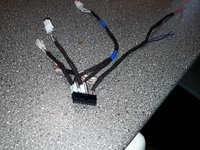
HF controller installed and wired in. Sound is from front speakers only (it was a challenge to fish out 2 x negative wires for front speakers), original mute function utilized in BE1460, power comes from lighter, BATT from radio. Harness:
20181025_171359.jpg
Ready product:

20181003_072027.jpg
Desoldering the original microphone barrel gave me a space for the new one, it is not soldered into the PCB but has a short lead going to its own small PCB seen on above picture. I omitted here intentionally all the steps like separating everything from each other with non conductive material, heat shrinks, connectors etc., these are all obvious. Everything works as it should, sound in speakers is clear, radio mutes the music on incoming call, person on the other end of the line can hear me pretty well however "could be better" as my lovely wife stated. There is a gain adjuster for the microphone, I think I need to tweak it a bit.
This is rather primitive project compared with what Jlaa wants to do however it works well for me. This project is not completed yet - HF has a Bluetooth music streaming capability and low level signal out for this purpose. Plan is to inject this signal between tape head and Dolby chips - use Spotify instead of cassette...
 
I think I'll start from power. My panel is powered through purple (+12V) and light blue wire (ground for electronics), be aware that yours could have different colors in the 8 wire cable with RJ45 connector. Applying +12V will lit up all buttons and green power LED. In fact it is all what you need if you want to wire in a remote control for gate etc. Buttons - constant +5V is present in common path connecting all of them, it is clear when you look at the board where buttons are. Pressing a button closes a path and sends +5V to the processing part of the board.

My dual channel remote controller is a tiny PCB with KeeLoq chip that requires +12V power and +6 to +12V signal for each channel to activate it, in fact it is a key fob less for battery and buttons. I just soldered 2 wires downstream of the 2 panel buttons and cut the conductive path behind the soldering, +5V is not going any further now that the remote controller. There are very convenient places to solder wires in, these are holes that transit from one side of PCB to another, just like they would be made for this purpose :) control) but the brightness level is just perfect in my opinion.


@darek_u thank you, the stuff you put in bold is exactly what I need to know. And, I think I know exactly what you are talking about w.r.t. the convenient places to solder wires in (the holes that go from one side of the PCB to the other side)
 

Who has viewed this thread (Total: 1) View details

Who has watched this thread (Total: 2) View details

Back
Top