• Hi Guest !

    Welcome to the 500Eboard forum.

    Since its founding in late 2008, 500Eboard has become the leading resource on the Internet for all things related to the Mercedes-Benz 500E and E500. In recent years, we have also expanded to include the 400E and E420 models, which are directly related to the 500E/E500.

    We invite you to browse and take advantage of the information and resources here on the site. If you find helpful information, please register for full membership, and you'll find even more resources available. Feel free to ask questions, and make liberal use of the "Search" function to find answers.

    We hope you will become an active contributor to the community!

    Sincerely,
    500Eboard Management

Center Console Bulb

ARRRRRGHHHHH!!!!! Kill it! Kill it with .... uh..... don't use fire. But kill all that crap!!!
GOD-DAMN this bloodlust is sexy!! Damn, I got TURNED ON and I like the approach!! 😄

Note that Purple is "vi" and that the purple wire you speak of is mixed with a different color (is it white? maybe grey?)
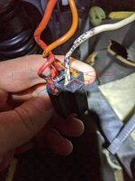
Just to clarify, just in case: my understanding is that purple/white cable was chopped and directed into some sort of a connector into which some sort of Bosch thing plugged. This some sort of a connector spits out orange cable that goes away and this same connector spits out a white cable that reconnects to the other part of the purple/white cable.

You say chop it without thinking twice and reconnect purple/white cable into a direct connection without any hesitation, right?

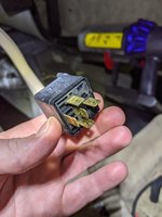
1621735626719.jpeg
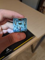
1621735634010.jpeg
1621735650587.jpeg
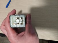
1621735657097.jpeg
 
GOD-DAMN this bloodlust is sexy!! Damn, I got TURNED ON and I like the approach!! 😄


Just to clarify, just in case: my understanding is that purple/white cable was chopped and directed into some sort of a connector into which some sort of Bosch thing plugged. This some sort of a connector spits out orange cable that goes away and this same connector spits out a white cable that reconnects to the other part of the purple/white cable.

You say chop it without thinking twice and reconnect purple/white cable into a direct connection without any hesitation, right?

No, what I mean is to work backwards and find wires that connect to nothing. If a wire connects to nothing and is obviously not an MB wire then delete it. The goal is to simplify what we are looking at.

The Bosch thing is a relay. Which terminal does the purple/wht wire connect to? 87 or 87a perhaps?

 
By the way, still no X6/1 in sight :)

View attachment 131328

It is entirely possible that x6/1 is gone and the previous “automotive electronics technicians” made their own connections to those airnozzle/gearshift/window switch lights with their “replacement” x6/1.

The way the Bosch relay works is that you have to apply 12v and ground to pins 85 and 86 respectively. This is typically done with a switch of some sort.

When you activate the switch (pins 85/86 show 12v) then pins 87 and 30 are connected. When you DEactivate the switch (pins 85/86 show 0 volts) then pins 87a and 30 are connected.

EDIT - WHAT THIS MEANS IS THAT IF WT/VI wire is connected to both pins 87a and 30 AND there is nothing connected to pins 85/86 then this means the relay is not energized and WT/VI IS UNBROKEN IN THIS STATE BC 87a AND 30 ARE CONNECTED AS “NORMALLY CLOSED”

Typically you do this when you want to switch some high-current thing on and off (like automotive exterior lighting) but don’t want all that current going through your puny switch and melting it. That’s why I wonder what terminal the violet/wt wire is connected to.

You are going through (electrical) baptism by 🔥 and doing well!
 
Last edited:
That’s why I wonder what terminal the violet/wt wire is connected to.
Thanks for bearing with my obtuseness. Thick purple/white cable connects pins 87 and 30 on the Bosch relay
17B.jpg
 
Thanks for bearing with my obtuseness. Thick purple/white cable connects pins 87 and 30 on the Bosch relay
View attachment 131329

Ok we are getting somewhere!

See here - What is a Bosch Relay | MGI SpeedWare

What this means is that when the relay is not energized, then pins 87a and 30 connect. ONLY WHEN THE RELAY IS ENERGIZED is WT/VI CONNECTED BC WHEN RELAY IS ENERGIZED, pin 87 and 30 are connected.

So someone decided to break VI/WT.

Questions -
1) where do pins 85/86 go?
2) where does pin 87a go?
Ok, sorry - clarification: purple/white cable goes into 30 and comes out of 87A

  • 85 is connected 30
  • 86 (orange cable) has a resistor (?) between it and 30
19D.jpg

86 (orange cable) leads to a connector that is not connected to anything:
20F.jpg
 
EDIT - @kiev you can double check the hypothesis that x6/1 is butchered by using the multimeter to test for continuity between socket 58D and the positive lead for the little bulbs that are supposed to light up, like the gear selector bulb.
I must be doing something wrong, but checking for continuity between 58D and a gear selector bulb socket OR front driver window switch connector (pin that is fed by blue/grey wire) I get a beep, which, my understanding, means the circuit is intact.... *head scratch*. I have now tried a total of 3 N40 relays - original + 2 used one from eBay - so it's definitely not it.

I don't know if this is a useful info, but checking for circuit continuity between 58D and driver window switch:
  • the very top left pin (1) and the very bottom (2, fed by blue/grey cable), the meter beeps and there is perfect 0 ohm resistance
  • very bottom left (3) no beeping, no reading
  • second row from the top pins 4 and 5, I get like close to 2000 Ohm of resistance

1621743795938.jpeg
 
Ok, sorry - clarification: purple/white cable goes into 30 and comes out of 87A

Ok this means when the relay is not energized, that 30 and 87a are connected (that WT/VI is unbroken).

  • 85 is connected 30
  • 86 (orange cable) has a resistor (?) between it and 30
View attachment 131331
No idea what is going on here … btw that is a diode between 86 and 30 …. Looks totally hack-y to do it that way.

86 (orange cable) leads to a connector that is not connected to anything:
View attachment 131332

So tentatively I think that means the relay will never be energized …. And that reconnecting the WT/VI wire to itself shooooouuuulllld be ok …. But before doing anything like that, where does 87 and 85 (and 30, which is tied to 85) go?!!!?!
 
I must be doing something wrong, but checking for continuity between 58D and a gear selector bulb socket OR front driver window switch connector (pin that is fed by blue/grey wire) I get a beep, which, my understanding, means the circuit is intact.... *head scratch*. I have now tried a total of 3 N40 relays - original + 2 used one from eBay - so it's definitely not it.

Good!!!! So 58D and positive lead of gear selector bulb are connected? That’s good!
Can you try to test to see if the ground side of the gear selector bulb is actually grounded? Use the multimeter to test for continuity between the gear selector’s ground lead and AN ACTUAL GROUND IN THE CAR THAT REALLY WORKS……

I don't if this is a useful info, but checking for circuit continuity between 58D and driver window switch:
  • the very top left pin (1) and the very bottom (2, fed by blue/grey cable), the meter beeps and there is perfect 0 ohm resistance
  • very bottom left (3) no beeping, no reading
  • second row from the top pins 4 and 5, I get like close to 2000 Ohm of resistance

View attachment 131334
Hmmmm … can you remind me what are all those pons in the window switch connector supposed to be?
 
Good!!!! So 58D and positive lead of gear selector bulb are connected? That’s good!
Can you try to test to see if the ground side of the gear selector bulb is actually grounded? Use the multimeter to test for continuity between the gear selector’s ground lead and AN ACTUAL GROUND IN THE CAR THAT REALLY WORKS……
0 ohm and a beep between gear selector bulb socket and 2 ground points: W12 near gear selector and one where front ceiling light is... Ditto from driver window switch....

Jlla, put me out of my misery please and validate or not my understanding:

  1. fuse 9 powers 58d. N40 takes 58d reference voltage and powers 58D with the same fuse 9, according to that reference voltage. Correct?
  2. 58D via X6/1 powers illumination of all of the switches that don't light up in my car. Correct?

SO.... If 58d does output power into N40 relay (3 different N40s now tested), AND 58D to gear selector light and driver window switch continuity tests out ok. AND the ground tests out OK, then... WTF am I not understanding? Why is there no illumination? I know that I'm the weak link here, so help me grasp it, please
 
Apologies for jumping in here, but I wanted to interject with some information that may be helpful concerning the center console switches. When I saw Kiev having similar problems and the discussion in this string about relay 004 545 08 32 (behind the instrument cluster lower right) I ordered one on ebay for $15 and it actually resolved my integral lights in several switches on the center console as well as the integral lights in the rear window switches. I got lucky on this one. The left pic is with the bad relay. The right pic is with the new relay installed.
 

Attachments

  • Bad Relay.jpeg
    Bad Relay.jpeg
    1.3 MB · Views: 5
  • Relay 004 545 08 32.jpeg
    Relay 004 545 08 32.jpeg
    2 MB · Views: 5
  • With New Relay.jpeg
    With New Relay.jpeg
    1.4 MB · Views: 5
Apologies for jumping in here, but I wanted to interject with some information that may be helpful concerning the center console switches. When I saw Kiev having similar problems and the discussion in this string about relay 004 545 08 32 (behind the instrument cluster lower right) I ordered one on ebay for $15 and it actually resolved my integral lights in several switches on the center console as well as the integral lights in the rear window switches. I got lucky on this one. The left pic is with the bad relay. The right pic is with the new relay installed.
I got 2 used ones from eBay - no luck...

1621747416396.jpeg
 
Last edited:
I didn't reinstall the relay bracket screw yet because I couldn't get my hand or a wrench back there, so if you need any voltage tests or measurements checked for that relay or wiring to it, let me know while it's still accessable. At least mine appears to be a known good system right now.
 
I didn't reinstall the relay bracket screw yet because I couldn't get my hand or a wrench back there, so if you need any voltage tests or measurements checked for that relay or wiring to it, let me know while it's still accessable. At least mine appears to be a known good system right now.
Yeah, it's very tight in there... I don't know what measurements you could do no yours that would help me... For fun I measured both of mine and pin 30 to 58D gave me 9 volts on one unit and 3 on the other. They both were connected several times tonight at one point or another
 
Yeah, it's very tight in there... I don't know what measurements you could do no yours that would help me... For fun I measured both of mine and pin 30 to 58D gave me 9 volts on one unit and 3 on the other. They both were connected several times tonight at one point or another
So you've got the relay plugged in but just loose enough to touch the pin with a volt meter and check the voltage? I presume that's with the parking lights on? Would it help you if I checked those two terminals on mine?
 
So you've got the relay plugged in but just loose enough to touch the pin with a volt meter and check the voltage? I presume that's with the parking lights on? Would it help you if I checked those two terminals on mine?
No! Both are laying on my desk. Capacitors inside must be storing some charge
 
What you're looking at with the aftermarket Bosch relay with the orange wire and spliced Violet/White factory wires is a starter kill switch that was part of a poorly installed alarm system. Chop that thing out, and reconnect both ends of the Violet/White wire.
Thank you!
 
Or maybe their brown wire to ground point w12 is cut?
After looking at the rat's nest flustercluck of aftermarket alarm, I'm 99.036% sure that a brown wire along the W12 path has been disrupted.

Aftermarket alarm units usually have a few "negative trigger" inputs to sound the alarm when the trunk or door is opened. The "installer" probably cut and spliced a door trigger wire (which conveniently grounds to W12). With the alarm brain removed, there's now a ground break in the W12 path.
 
0 ohm and a beep between gear selector bulb socket and 2 ground points: W12 near gear selector and one where front ceiling light is... Ditto from driver window switch....

Jlla, put me out of my misery please and validate or not my understanding:

  1. fuse 9 powers 58d. N40 takes 58d reference voltage and powers 58D with the same fuse 9, according to that reference voltage. Correct?
  2. 58D via X6/1 powers illumination of all of the switches that don't light up in my car. Correct?

SO.... If 58d does output power into N40 relay (3 different N40s now tested), AND 58D to gear selector light and driver window switch continuity tests out ok. AND the ground tests out OK, then... WTF am I not understanding? Why is there no illumination?
The title of this post should be 2 Steps Forward and One Step Back or Even Though We Live in the Age of Limitless Information, Not Everything is Real News --- Some of It is Fake!

Okay. I looked back at the diagrams which we had been working off of --- the Electrical Troubleshooting Manual "As of MY1986" diagrams here below. Indeed, assuming these diagrams are legit, then your understanding is totally correct. The diagram is below and is from this source: https://freescruz.com/.priv/W124/w124CD1/Program/ETM/ETM.pdf .

1621748103847.png

HOWEVER, Cross referencing this with ANOTHER diagram here below, which is from this source:


1621749564050.png

THERE SEEM TO BE SOME DIFFERENCES. @kiev 1000 apologies if I have led you astray - I was unprepared for the wiring diagrams across different sources on the Intrawebz being in disagreement with each other.

Please let me highlight the differences that this new diagram represents over the previous diagram:

  • In the previous diagram:
    • X6 feeds N40 through pin4 58d
    • N40 feeds X6/1 through pin2 58D
    • x6/1 then feeds L/R air nozzle/gear selector illumination
  • In the new diagram
    • Instrument Cluster A1 feeds "Circuit 58d Connector Sleeve" at z81
    • z81 feeds N40 through pin4 (note there is no mention if this is 58d or 58D ... just pin 4) No mention of x6 whatsoever.
    • N40 feeds x6/1 through pin2 (note that this is referred to as "circuit 58d")
    • x6/1 "circuit 58d" feeds L/R air nozzle/gear selector illumination
Assuming that the new diagram is "more correct" then perhaps we can postulate the following hypotheses:

  • Yes, fuse 9 powers N40 in both old and new versions of the electrical diagram
  • Perhaps your 124.034 does NOT have x6. Maybe it only has x6/1. And maybe that big block of wires meeting each other near the ashtray is indeed x6/1.
  • Forget about 58D and 58d nomenclature. Just use pin 2 on the N40 socket as the pin feeding the illumination to L/R Air nozzle and gear selector.
  • Forget about 58D and 58d nomenclature. Just use pin 4 on the N40 socket as the pin that the N40 relay is grabbing the "reference signal" from.
Does this information change the results of your testing when you are testing for continuity between the positive lead of the gear selector illumination bulb and the output of N40 (pin 2)?
 
After looking at the rat's nest flustercluck of aftermarket alarm, I'm 99.036% sure that a brown wire along the W12 path has been disrupted.

Aftermarket alarm units usually have a few "negative trigger" inputs to sound the alarm when the trunk or door is opened. The "installer" probably cut and spliced a door trigger wire (which conveniently grounds to W12). With the alarm brain removed, there's now a ground break in the W12 path. (or a ground break in W1 path according to the "new diagram")
@speedy300dturbo speaks the truth!
It sure smells like a cut or disconnected ground somewhere.

... checking for continuity between 58D* and a gear selector bulb socket ..... I get a beep, which, my understanding, means the circuit is intact.... *head scratch. ..
...AND 58D* to gear selector light and driver window switch continuity tests out ok. AND the ground tests out OK, then... WTF am I not understanding? Why is there no illumination? I know that I'm the weak link here, so help me grasp it, please
*assuming this is pin 2 of the N40 socket, then powering this and ground with a 9v battery HAS TO LIGHT UP the gear selector bulb. If it doesn't light up the bulb, then either you are accidentally measuring continuity incorrectly somehow or your bulbs are all blown out or the 9v battery is dead. Maybe a fresh mind in the morning is in order? 😁
 
A simple test is to use your DMU to probe for voltage at the grey wire in the bulb holder socket at the lateral air vents, and do the same at the window switches. Red lead of DMU to grey wire, and black lead to chassis ground. If your DMU reads 12V+, that's great and your lighting relays and associated grey wire pathways are A-okay, indicating a fault in the W12 or W1 ground path.
 
@Jlaa, thank you for your work. I'll do a fresh approach in the morning as it's almost 3 am. One thing: the connector can only plug one way into the N40. N40 has "31", "30", "58d", "58D" stamped next to pins. N40 connector has tiny "1", "2", "3", "4" stamped next to its pins. The pin with tiny 2 stamped on the connector connects to 58D on N40 and pin with a tiny 4 connects to 58d.

Yeah, there is continuity - a beep and 0 ohm - between 58D (2) and bulb socket of the gear level illumination...

1621752799703.jpeg
 
A simple test is to use your DMU to probe for voltage at the grey wire in the bulb holder socket at the lateral air vents, and do the same at the window switches. Red lead of DMU to grey wire, and black lead to chassis ground. If your DMU reads 12V+, that's great and your lighting relays and associated grey wire pathways are A-okay, indicating a fault in the W12 or W1 ground path.
Right!!!!

Also @kiev, how is the front ashtray illumination? Does it light up? Does the lighter work?
Note that front ashtray, L/R Air Nozzle Illumination, Gear Selector illumination, and "Exterior Lamp Switch Illumination" all share W1 for ground.

Also note that W1 is behind the instrument cluster.
1621753389004.png

1621753154323.png
 
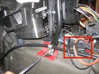
Kiev, I noticed a disconnected wire here (circled in red). Can you trace this and tell us where it runs?

You might want to remove the plastic footrest panel (pull door sill plate off, pull back fuzzy door sealing strip, remove one screw near the bottom) because it looks like more aftermarket wiring is hiding behind there.
 

Attachments

  • [500Eboard] PXL_20210522_232814998.jpg
    [500Eboard] PXL_20210522_232814998.jpg
    1.8 MB · Views: 8
A simple test is to use your DMU to probe for voltage at the grey wire in the bulb holder socket at the lateral air vents, and do the same at the window switches. Red lead of DMU to grey wire, and black lead to chassis ground. If your DMU reads 12V+, that's great and your lighting relays and associated grey wire pathways are A-okay, indicating a fault in the W12 or W1 ground path.
thanks, I will do this again tomorrow. In prior measurements, blue/gray wires of illuminated switches produced >7 volts, and of non-illuminated produced zero volts. But I will recheck again tomorrow

how is the front ashtray illumination? Does it light up? Does the lighter work?
Ashtray illumination works, lighter socket works! (Charges phone, powers radar detector). 😂
 
thanks, I will do this again tomorrow. In prior measurements, blue/gray wires of illuminated switches produced >7 volts, and of non-illuminated produced zero volts. But I will recheck again tomorrow
On balance, 7 volts seems kinda low doesn't it? (Assuming this is when powered with +12v?)
 
Ashtray illumination works, lighter socket works! (Charges phone, powers radar detector). 😂
Another test: Ignition on, red probe of DMM to center pin of lighter socket, black probe to brown wire pin of air vent nozzle bulb holder. This will determine whether the brown wire at the bulb holder has continuity with chassis ground.
 
What you're looking at with the aftermarket Bosch relay with the orange wire and spliced Violet/White factory wires is a starter kill switch that was part of a poorly installed alarm system. Chop that thing out, and reconnect both ends of the Violet/White wire.
I believe Speedy has nailed it. I was thinking the exact same thing - starter kill/lockout. That bundle may go to the ignition switch, btw.

1621780207563.png


I'm 99.036% sure that a brown wire along the W12 path has been disrupted.

Aftermarket alarm units usually have a few "negative trigger" inputs to sound the alarm when the trunk or door is opened. The "installer" probably cut and spliced a door trigger wire (which conveniently grounds to W12). With the alarm brain removed, there's now a ground break in the W12 path.
I think he's correct here as well... very likely the root cause of all the issues is butchered wiring from the alarm install. The fun part will be tracking it down.

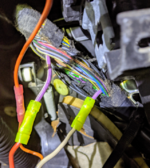
Since the alarm is gone anyway, I'd see if it's possible to eliminate all the non-factory components, and return the wiring to original, un-spliced condition. This will be a challenge due to the short lengths available, for example on the thick purple/white wire. If you cut it any shorter, it will be difficult to spice the ends together. Try to un-crimp the yellow connectors and pull the bare wire out intact. There may be enough length to re-connect them directly either with solder, a solder-type splice connector, or a quality crimp splice.

:shocking:
 
First of all, @speedy300dturbo, nice to have you onboard in this thread. Please stay :). @gsxr, @Jlaa - :bowdown:. Secondly, I read all of posts, but my mind get overwhelmed here and there and if I'm ignoring an obvious piece of information put forward by either of you, please do reiterate it again. I'm starting from a very low resolution of understanding, so may not connect the dots which are readily apparent to you


After looking at the rat's nest flustercluck of aftermarket alarm, I'm 99.036% sure that a brown wire along the W12 path has been disrupted.
@speedy300dturbo speaks the truth!
It sure smells like a cut or disconnected ground somewhere.
I think he's correct here as well... very likely the root cause of all the issues is butchered wiring from the alarm install. The fun part will be tracking it down.
So that's unanimous!


Good!!!! So 58D and positive lead of gear selector bulb are connected? That’s good!
Can you try to test to see if the ground side of the gear selector bulb is actually grounded? Use the multimeter to test for continuity between the gear selector’s ground lead and AN ACTUAL GROUND IN THE CAR THAT REALLY WORKS……


Hmmmm … can you remind me what are all those pons in the window switch connector supposed to be?
I was hoping that you might now and by some miracle this information might lead you to a serendipitous discovery. Hoping for a lucky shot

A simple test is to use your DMU to probe for voltage at the grey wire in the bulb holder socket at the lateral air vents, and do the same at the window switches. Red lead of DMU to grey wire, and black lead to chassis ground. If your DMU reads 12V+, that's great and your lighting relays and associated grey wire pathways are A-okay, indicating a fault in the W12 or W1 ground path.
Does DMU refer to a multi meter?
By grey wire, you refer to blue/grey illumination wire, right? Just confirming

Kiev, I noticed a disconnected wire here (circled in red). Can you trace this and tell us where it runs?

You might want to remove the plastic footrest panel (pull door sill plate off, pull back fuzzy door sealing strip, remove one screw near the bottom) because it looks like more aftermarket wiring is hiding behind there.
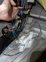
I did remove plastic footrest. There is definitely wiring modifications all over the footwell area. That disconnected wire you've circled, along with a bunch of other wires was not connected to anything. They basically fell out as soon as a I pulled on them slightly

1621792011898.jpeg

return the wiring to original, un-spliced condition. This will be a challenge due to the short lengths available, for example on the thick purple/white wire. If you cut it any shorter, it will be difficult to spice the ends together. Try to un-crimp the yellow connectors and pull the bare wire out intact. There may be enough length to re-connect them directly either with solder, a solder-type splice connector, or a quality crimp splice.
Dave, could you give me a dumbed down, simple version of correct way to un-crimp yellow connectors?

As far as "re-connect them directly either with solder, a solder-type splice connector, or a quality crimp splice", my understanding is that diving into the footwell with a soldering iron, a solder, and trying to melt it onto a wire connection would be an acrobatic trick of the highest magnitude? Or am I wrong and that's how it should be done, I just have a wrong picture in my head? As far as solder-type connector vs quality crimp splice - which one? I have no experience at all.... Thanks
 
I found 2 ground points below parking brake pedal, close to the driver's door. Do you think they are original, and were made by installer to accommodate alarm install?

The upper ground point has 2 black wires that lead to a COMBO of white aftermarket connector + fused "assembly". This COMBO is unplugged i.e. whatever it was plugged into seems to be gone

Lower ground leads to dual aftermarket Bosch relays (also circled)

30Z.jpg
 
So, there is a thick sheathing of MB wires that is stored in the black box in the floor and routes into the driver side fender (circled in red). Only a blue wire from that sheathing is tapped into and leads to dual Bosch relays (light green parallelogram). Ground leads into those dual Bosch relays as well.

31Z.jpg

ONLY one RED cable leads out from the dual Bosch relays (nothing else that leads out from dual Bosch relays is connected to anything) that currently connects to anything, some sort of factory terminal. There is a split in the RED cable where it lead to the same white connector + fused assembly COMBO that isn't plugged into anything
32Z.jpg
 
First of all, @speedy300dturbo, nice to have you onboard in this thread. Please stay :). @gsxr, @Jlaa - :bowdown:. Secondly, I read all of posts, but my mind get overwhelmed here and there and if I'm ignoring an obvious piece of information put forward by either of you, please do reiterate it again. I'm starting from a very low resolution of understanding, so may not connect the dots which are readily apparent to you


So that's unanimous!


I was hoping that you might now and by some miracle this information might lead you to a serendipitous discovery. Hoping for a lucky shot


Does DMU refer to a multi meter?
By grey wire, you refer to blue/grey illumination wire, right? Just confirming


I did remove plastic footrest. There is definitely wiring modifications all over the footwell area. That disconnected wire you've circled, along with a bunch of other wires was not connected to anything. They basically fell out as soon as a I pulled on them slightly

View attachment 131358


Dave, could you give me a dumbed down, simple version of correct way to un-crimp yellow connectors?

As far as "re-connect them directly either with solder, a solder-type splice connector, or a quality crimp splice", my understanding is that diving into the footwell with a soldering iron, a solder, and trying to melt it onto a wire connection would be an acrobatic trick of the highest magnitude? Or am I wrong and that's how it should be done, I just have a wrong picture in my head? As far as solder-type connector vs quality crimp splice - which one? I have no experience at all.... Thanks
IMHO it is too difficult to manually solder in such a cramped space and short wires .... even for an experienced person. However, IMHO regular crimping (and I mean with a quality ratcheting crimp tool) with just a crimp connector is still kind of amateurish.

Watch this video for a an overview of three kinds of repair connections:
and then watch this video for the a good kind of self soldering connector that requires a heat gun:

I am sorry @kiev it makes me furious to view your pictures. SO MUCH CRAPTASTIC HOMEBREW SHIT WIRING. Especially that janky “fuse holder” for the yellow blade fuse. 😱🙄🤬🤬😡😡😡

BTW I don’t think those ground you circled are factory ... else there would be a bunch of factory brown wires attached...
I'll order a heat gun a self soldering connectors from Amazon. I want to purge this crap out and hopefully finding the illumination issue in the process
 
After looking at the rat's nest flustercluck of aftermarket alarm, I'm 99.036% sure that a brown wire along the W12 path has been disrupted.

Aftermarket alarm units usually have a few "negative trigger" inputs to sound the alarm when the trunk or door is opened. The "installer" probably cut and spliced a door trigger wire (which conveniently grounds to W12). With the alarm brain removed, there's now a ground break in the W12 path.
@speedy300dturbo, do you suggest that W12 ground is itself compromised and NOT an individual connections of switches to it? Because window switch-to-ground continuity-wise checks out fine.

How would YOU start tracing a break in the W12 itself? It's located next to gear lever, slightly forward. Would you just follow it's path from there to see where the break is? I see that mine snakes along the trans tunnel for a bit and than goes under the passenger seat. Following it would require me to remove said seat, carpeting under it, etc :eek:
kiev said:
... checking for continuity between 58D* and a gear selector bulb socket ..... I get a beep, which, my understanding, means the circuit is intact.... *head scratch. ..
kiev said:
...AND 58D* to gear selector light and driver window switch continuity tests out ok. AND the ground tests out OK, then... WTF am I not understanding? Why is there no illumination? I know that I'm the weak link here, so help me grasp it, please

*assuming this is pin 2 of the N40 socket, then powering this and ground with a 9v battery HAS TO LIGHT UP the gear selector bulb. If it doesn't light up the bulb, then either you are accidentally measuring continuity incorrectly somehow or your bulbs are all blown out or the 9v battery is dead. Maybe a fresh mind in the morning is in order? 😁
I just did this again, for the Nth time. Indeed it is a pin #2 (58D on N40 relay) of the N40 connector. Powering it with a positive lid from the 9 volt battery and touching a W12 ground or ground point of the ceiling light with a negative lid from the same 9 volt battery - I get nothing. Total darkness.

If I power in an identical manner pin #4 (58d on N40 relay) - instrument cluster lights up along with hazard light switch. I can also power an individual window switch with same 9 volt battery on my desk and it lights up. *Switches are not incandescent bulbs, but are LEDs, I think (?)*

Continuity between pin 2 and Ground W12 - checks out, beep and perfect zero ohm; pin 2 - to pin on window switch connector - checks out, beep and perfect 0 ohm! pin 4 (58d) to W12 I get 0.26 ohm of resistance; same pin 4 to window switch connector: 0.26 ohm.

*When meter is in "check continuity mode", default reading is 1, so when there is continuity and it beeps and switches to zero, I know I'm doing it right...
1621816111258.png

A simple test is to use your DMU to probe for voltage at the grey wire in the bulb holder socket at the lateral air vents, and do the same at the window switches. Red lead of DMU to grey wire, and black lead to chassis ground. If your DMU reads 12V+, that's great and your lighting relays and associated grey wire pathways are A-okay, indicating a fault in the W12 or W1 ground path.
I did these tests again. I get no voltage on switches that are expected to light up. Recirculating switch, rear defrost switch which DO light up, they measure ~10.8 volts


On balance, 7 volts seems kinda low doesn't it? (Assuming this is when powered with +12v?)
I remeasured, I get ~10.8 volts


I shall try to locate W1 ground point...
 
@kiev, what happens if you touch the positive of a 9v battery to pin2 of N40 relay (58D) and the negative terminal of the 9v battery to the negative lead of window switch …. Or negative lead of trans gear selector bulb directly?

In this manner we bypass car ground and see if indeed the indiv wires to w12 and/or w1 from your non-illuminating switches are cut.

Also what if we do the reverse? Positive term of 9v battery to positive illumination lead of window switches / gear selector bulb and negative term of 9v battery to some chassis ground?
 
@speedy300dturbo,

Continuity between pin 2 and Ground W12 - checks out, beep and perfect zero ohm; pin 2 - to pin on window switch connector - checks out, beep and perfect 0 ohm! pin 4 (58d) to W12 I get 0.26 ohm of resistance; same pin 4 to window switch connector: 0.26 ohm.

*


I just reread your post @kiev … are you saying that pin 2 58D of n40 socket is short circuited? Pin 2 is supposed to provide 12 volts!!!!!!
 
@kiev, what happens if you touch the positive of a 9v battery to pin2 of N40 relay (58D) and the negative terminal of the 9v battery to the negative lead of window switch …. Or negative lead of trans gear selector bulb directly?

In this manner we bypass car ground and see if indeed the indiv wires to w12 and/or w1 from your non-illuminating switches are cut.

Also what if we do the reverse? Positive term of 9v battery to positive illumination lead of window switches / gear selector bulb and negative term of 9v battery to some chassis ground?
So, nothing every which way. I've tried all of the combinations you've asked and then some. Switch never lights up. (everything's disconnected, including a thick tie of cables to instrument cluster. I did this in total darkness to see even the faintest signs of life, but none...

This is the back of the driver window switch. Positive from 9V battery to pin 1 and negative from 9V battery to pin 2 and it lights up. So the switch definitively works.
1621823030137.jpeg


I just reread your post @kiev … are you saying that pin 2 58D of n40 socket is short circuited? Pin 2 is supposed to provide 12 volts!!!!!!
Ahhh, is this the long awaited moment of serendipity?

Pin 2 (58D) of the connector that plugs into N40 relay does not out put any voltage. I was under the impression that it is fed voltage WHEN it's plugged into N40 relay, with the help of N40, which takes reference from pin 4 (58d) and uses fuse 9 to send correct voltage to pin 2 (58D)..... No? 🤕
 
Last edited:
So, nothing every which way. I've tried all of the combinations you've asked and then some. Switch never lights up. (everything's disconnected, including a thick tie of cables to instrument cluster. I did this in total darkness to see even the faintest signs of life, but none...

This is the back of the driver window switch. Positive from 9V battery to pin 1 and negative from 9V battery to pin 2 and it lights up. So the switch definitively works.
View attachment 131391


Ahhh, is this the long awaited moment of serendipity?

Pin 2 (58D) of the connector that plugs into N40 relay does not out put any voltage. I was under the impression that it is fed voltage WHEN it's plugged into N40 relay, with the help of N40, which takes reference from pin 4 (58d) and uses fuse 9 to send correct voltage to pin 2 (58D)..... No? 🤕


Correct, pin2 (58D) of the socket for N40 does not output any voltage by itself without N40 present, but you also stated that you tested for continuity between

“Continuity between pin 2 and Ground W12 - checks out, beep and perfect zero ohm;”. <— ARE YOU SURE? You mean Pin 2 58D of N40 Socket right? Is this the same with instrument cluster connected and not connected?

If this is true then this means somehow the wires that go to pin 2 58D are shorted out (connected to ground)!!!

That would be quite bad and I would not be surprised if every N40 relay plugged in were fried by this condition if true.

If indeed pin 2 58D of the N40 socket is shorted to ground, then do what it takes to find out what is shorting it to ground. Unwrap the wires.
 
Last edited:
@kiev, what happens if you touch the positive of a 9v battery to pin2 of N40 relay (58D) and the negative terminal of the 9v battery to the negative lead of window switch …. Or negative lead of trans gear selector bulb directly?

In this manner we bypass car ground and see if indeed the indiv wires to w12 and/or w1 from your non-illuminating switches are cut.

Also what if we do the reverse? Positive term of 9v battery to positive illumination lead of window switches / gear selector bulb and negative term of 9v battery to some chassis ground?

So, nothing every which way. I've tried all of the combinations you've asked and then some. Switch never lights up. (everything's disconnected, including a thick tie of cables to instrument cluster. I did this in total darkness to see even the faintest signs of life, but none...


@kiev this is strange. If powering your windows switches both ways with the 9v battery (please refer to bold above) doesn’t work then this suggests that BOTH the wire leading away from pin 2 58D of the n40 socket AND the wires connecting window switches to ground (w12 or w1) are cut. Are you 200% sure?

Again just to be repetitive and with more clarity, the two tests are:

TEST 1

what happens if you touch the positive of a 9v battery to pin2 of N40 relay (58D) and the negative terminal of the 9v battery DIRECTLY to the negative terminal of ONE window switch illumination….

You may have to fashion a jumper wire of some sort but the positive terminal of the window switch should be connected to the car and the negative terminal of the window switch should NOT be connected to the car.

TEST 2

Also what if we do the reverse? Positive term of 9v battery DIRECTLY to positive illumination terminal of ONE window switch bulb and negative term of 9v battery to some chassis ground like w12 or w1?

You may have to fashion a jumper wire of some sort but the NEGATIVE terminal of the window switch should be connected to the car and the POSITIVE terminal of the window switch should NOT be connected to the car.

POTENTIAL RESULTS

  • If test 1 works and test 2 fails then this means your window switch illumination is not tied to ground. Ground for these switches (like w12 or w1) is cut
  • If test 2 works and test 1 fails then this means your window switch illumination is not tied to N40 socket pin 2 58D. Somehow that wire is cut
  • If BOTH test 1 AND test 2 fail then this means both ground is cut AND the wire coming from N40 socket pin 2 58D is cut. This double-failure would be improbable but not impossible.
 
Last edited:
The X6/1 terminal block is a small rectangular thingy with a flip-up cover: Pic108.jpg

If the brown wires at the window switches and air vent nozzles have continuity with ground and you are NOT seeing 12v+ at the grey wires, then there's something going on with what's feeding X6/1.
 
Not entirely related to the illumination issue, but we can start cleaning up some of that messy wiring. You can cut the aftermarket red and ground wires, cut off the splices at the factory blue lock/unlock wire and connect both ends back together, and throw the taped up relay bundle in the trash.[500Eboard] 31Z.jpeg
 
@Jlaa, I'll retest for the Nth time, hopefully tomorrow. Had some time to work on the car on Saturday and figured I'll give a newly arrived heat gun and self-soldering joints a try. Need some results - don't like being stuck, and cleaning up wires is some sort of a result, even if not really tangible

The X6/1 terminal block is a small rectangular thingy with a flip-up cover: View attachment 131445

If the brown wires at the window switches and air vent nozzles have continuity with ground and you are NOT seeing 12v+ at the grey wires, then there's something going on with what's feeding X6/1.
Speedy, my man, is your car a W124 with a V8? Or am I nucking futs? I don't have an X6/1 on my 1993 400E and it doesn't look like it ever was there. Judging by the lack of a tie of brown ground cables in my picture, that are present in yours, yours is probably not a V8 model?

1622350470718.jpeg


Not entirely related to the illumination issue, but we can start cleaning up some of that messy wiring. You can cut the aftermarket red and ground wires, cut off the splices at the factory blue lock/unlock wire and connect both ends back together, and throw the taped up relay bundle in the trash.View attachment 131446
Looks much better now.
1622350692769.jpeg

I've got two remaining wires that are going from footwell towards engine compartment (looks like to a fuse box). Once I undo them, I'm done with the whole mess that you guys saw in earlier pictures. Do you happen to know if to lift up fuse box I just need to undo a few visible screws, or is it more complex?
1622350935681.jpeg
 
Last edited:
I've got two remaining wires that are going from footwell towards engine compartment (looks like to a fuse box). Once I undo them, I'm done with the whole mess that you guys saw in earlier pictures. Do you happen to know if to lift up fuse box I just need to undo a few visible screws, or is it more complex?
It's not simple to lift up the fuse box, and I don't think it will move more than a few inches? However, I've never tried.

You should be able to find the 2 offending wires in the engine compartment, if you hunt around long enough. If you can find where they terminate and disconnect them, the wires should pull back through into the passenger compartment. Just make sure there's not a hole left in the rubber boot that could allow water to enter... or, cut the wires on each side of the boot and leave a short section in place to fill the hole(s).

:rugby:
 
Kiev, it's entirely possible that on V8 124 models, X6/1 was moved or consolidated with X6 due to the widening of the transmission tunnel. I can't say for sure... it's been a while since I had a V8 center console apart.

The two remaining wires that run to the engine compartment are likely for the aftermarket alarm siren. See if there's a non-factory looking siren around the fuse box / brake booster or ABS pump area.
 
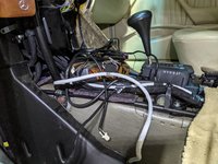
Do you guys guess this bright blue thick cable that goes up the steering column is factory or aftermarket?

PXL_20210530_021121207.jpg
 
The two remaining wires that run to the engine compartment are likely for the aftermarket alarm siren. See if there's a non-factory looking siren around the fuse box / brake booster or ABS pump area.
Found it. The siren was actually by windshield washer fluid container and a "brain" (?) Seco-larm ss-057 was neatly tucked close to driver height. Cut their respective cables and pulled them into the driver's foot well. Now all of this tragedy is out:
?hash=2185a69951eb792c169eb7f27c02fa0a.jpg

And foot well looks cleaner. Just need to rewrap cables into a tie:
PXL_20210530_223055927.jpg
 

Attachments

  • PXL_20210530_222024686.jpg
    PXL_20210530_222024686.jpg
    3.9 MB · Views: 11

Who has viewed this thread (Total: 2) View details

Who has watched this thread (Total: 1) View details

Back
Top