Follow along with the video below to see how to install our site as a web app on your home screen.
Note: This feature may not be available in some browsers.
I think you're right Dave. Lower screw secures 2 ties of cables + a single cable. All blue grey. One ties of blue/grey cables goes towards switches above HVAC, the other tie of cables goes towards power window switches. One single blue/grey cable goes to, my understanding based on JLAA's pointers to audio fader switchThe two screws are almost certainly X6/1, appears to be all Gray/Blue wires there.
@kiev, good progress through process of elimination. Let's try to answer the question "Does the blue arrow point to X6/1"?
The answers to the following questions may help us nudge closer to the answer:
Interestingly (or not). While blue/grey cables from power windows and mirror switches AND rear head restraint switch AND rear dome light switch all go to X6/1Can you trace the gray/blue wire from the gear selector light socket? As you can see in the diagram below highlighted in blue, the gear selector light socket should connect directly into X6/1, and the light socket is right there, so close to the presumed X6/1.
Rear dome lamp switch works, as in turns the light on/off, but is NOT illuminating. Rear headrest lowering switch also works, but does not illuminate.Does the rear dome lamp switch work? As you can see the the diagram below highlighted in green, this is connected directly to X6/1 and your presumed-X6/1 you mentioned basically all reads 0.0 or 0.02 volts. Note that I think the switch works even while there is no key in the ignition ... I think.
The fader works, but does NOT illuminateDoes the fader switch illunination work? As you can see the the diagram below highlighted in green, this is connected directly to X6/1 and your presumed-X6/1 you mentioned basically all reads 0.0 or 0.02 volts.
Switch itself works, but not its illumination
- With the ignition switch in the on position, do all the X6/1 wires still meter out at 0.0 or 0.02 volts? Does the rear head restraint release switch illumination work? See diagram below highlighted in red..... this is connected directly to X6/1.
Have you either checked for voltage at the blue/gray wire, at the offending switch(es), with the switch unplugged. And/or, tried making the switch illuminate on the workbench by applying voltage to the appropriate pins?Switch itself works, but not its illumination
This is normal. Zero volts is the "no reading" state. Most meters, especially inexpensive ones, may drift to slightly above zero even when not touching anything. Or, when connected to a terminal, they may show a trace voltage... either way, 0 and 0.01 should be treated as zero / no voltage.Here is the thing. My cheap Amazon voltmeter always reads zero in default state. There is no "no reading" state. I checked several times both of the screws on X6/1, with ignition on, and headlights on, and sometimes they read "0", sometimes "0.01". More often it'll read "0". Maybe I'm generating static electricity?
X6/1 appears to be powered through fuse 9 and Illuminati module N40. It also connects through X6 to the instrument cluster where the illumination rheostat will "drain" power to dim the lights as desired. @Jlaa, do you concur?I think the issue is with X6/1 connection. The upper screw hold a tie of cables, which contain red/grey cable, which my understanding is the powering cable? this tie of cables joins other ties of cables, including a tie that contains gear selector illumination cable and disappears into the depth (see arrow in the 2nd photo)
@Jlaa, looking at schematic, where does X6/1 get its power from?
X6/1 appears to be powered through fuse 9 and Illuminati module N40. It also connects through X6 to the instrument cluster where the illumination rheostat will "drain" power to dim the lights as desired. @Jlaa, do you concur?
![]()
Yes! I have power windows and mirror adjustment switches from the center console removed. Their blue/gray cables read zero. On the other hand, blue/gray cable that feeds hazard lights switch, which does illuminate, reads >7 voltsHave you either checked for voltage at the blue/gray wire, at the offending switch(es), with the switch unplugged.
I've replaced all fuses in the fuse box a few years back, so it isn't likely it. I will pull the instrument cluster and check the N40. I hope I'm getting closerCheck fuse 9 as that feeds N40. Maybe check to see if N40 (behind instrument cluster) is connected/grounded properly or replace it.
The grey/red wire is secured by the upper screw on X6/1. The upper screw reads the same - zero or 0.01 v - as lower screw that secures all of blue/grey cables....you know your next step is to measure voltage on grey/red wire.
The grey/red wire is secured by the upper screw on X6/1. The upper screw reads the same - zero or 0.01 v - as lower screw that secures all of blue/grey cables....
Here it is:@Jlaa, would you please attach this image, but without any drawings on it? I'd like to have it clean so I can more precisely ask questions here
View attachment 131025
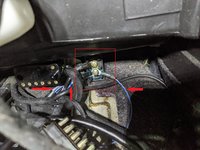
According to the ETM, the GY/BU wire from N40 is from terminal 58d, which leads to X6 (not X6/1) and is used as a reference to drive X6/1 via term 58D over the GY/RD wireMeanwhile, I believe I've located the N40 module. The connector that plugs into, one of its wires is grey/blue (red arrow, hopefully can be seen in the photo), which is probably gear selector illumination as it wasn't connected to X6/1:
View attachment 131026
View attachment 131027
@gsxr, Dave, "fuse 9", that would be in the regular fuse box, correct?
Looks like pin #2 at N40 should have a gray/red wire that goes to X6/1. Use your ohm meter to check for continuity (near zero resistance) between pin #2 and X6/1, if so, I'm getting more suspicious of the N40 relay (assuming fuse #9 is good).Meanwhile, I believe I've located the N40 module. The connector that plugs into, one of its wires is grey/blue (red arrow, hopefully can be seen in the photo), which is probably gear selector illumination as it wasn't connected to X6/1:
Correct!@gsxr, Dave, "fuse 9", that would be in the regular fuse box, correct?
Pin #1 (30) on the connector that plugs into N40 reads 12 volts(assuming fuse #9 is good).
I got a perfect zero ohm reading. There's also a separate, dedicated continuity test mode on the multimeter and it beeped when I connected red lid to pin #2 (58D) on the connector that plugs into N40 and black lid to X6/1Use your ohm meter to check for continuity (near zero resistance) between pin #2 and X6/1
I got a perfect zero ohm reading. There's also a separate, dedicated continuity test mode on the multimeter and it beeped when I connected red lid to pin #2 (58D) on the connector that plugs into N40 and black lid to X6/1![]()
***
Also, @Jlaa, I connected multimeter's red lid to pin #4 (58d) and black lid to a ground point of the front ceiling light. I got zero volts and 27 ohm of resistance...
*All tests with headlights on, max brightness on the rheostat
Do you pull these diagrams from the same EPC application you shared with me?@kiev - here is x6 (not to be confused with x6/1).
The diagrams are from the Electrical Troubleshooting Manual...... about 75 meg.Do you pull these diagrams from the same EPC application you shared with me?
…When I plug the connector back onto N40 module, with instrument cluster connected and lights on, measuring X6 to any ground point I get zero volts. Despite pin #4 (58d) of the connector that plugs into N40 producing 7-8 volts.
- Pin #4 (58d) - I get about 7-8 volts whether I ground it to ceiling light ground point OR pin #3 (31).
*** My heated rear window switch, which is also on X6/1 does illuminateWhich means X6/1 does receive power from pin #2 (58D). So then X6/1 is somehow butchered and is the cause??
@Jlaa, I read all of your posts and I totally appreciate you investing your time into my problem.
At some point over the last several days I did stare at vampire tap crap for 15 minutes, and I think you're right - it's connected to headunit power cable and not to anything else.
In theory, this may work, but I would make the test short. I don't fully understand the function of N40 but I think it's to not route the entire current draw of all interior illumination through the rheostat in the cluster. Adding the full current wouldn't be good long term, and there's a tiny risk of blowing the red fuse in the cluster (not a big deal, but be aware of this).Let’s also try and determine if x6/1 wiring is butchered. What if @kiev, with N40 relay removed, jumped pin 4 (58d) to pin 2 (58D) in the N40 connector? Then by counting which previously-dead-switches light up, he could see how much of x6/1 is butchered, if any.
In general, the super-secret diagrams supercede the old ones. Especially if labeled .034/.036 as this particular one is! Also, it is possible that X6/1 was relocated on the .034/.036 vs the non-V8 models. If so, you're still on the hunt to locate the darn thing...I know this ""super secret 1993 and above 034 and 036 wiring diagram" seems to conflict with the "after 1/1986 w124 wiring diagram" we have been using but aside from the inconsistency about the rear window defroster switch, they seem largely to agree.
Let’s also try and determine if x6/1 wiring is butchered. What if @kiev, with N40 relay removed, jumped pin 4 (58d) to pin 2 (58D) in the N40 connector? Then by counting which previously-dead-switches light up, he could see how much of x6/1 is butchered, if any.
Yeah routing that current thru the rheostat, even though it is not much, has me a tad worried too. Another way to test the degree of butchered-uppedness of x6/1, perhaps even safer then, is to:In theory, this may work, but I would make the test short. I don't fully understand the function of N40 but I think it's to not route the entire current draw of all interior illumination through the rheostat in the cluster. Adding the full current wouldn't be good long term, and there's a tiny risk of blowing the red fuse in the cluster (not a big deal, but be aware of this).
Yes! This would appear to be safer... apply voltage to the output of N40 sockets, and see what lights up. If everything gets lit (that's a good thing, I think, according to kids today) then it would appear N40 was dead.Yeah routing that current thru the rheostat, even though it is not much, has me a tad worried too. Another way to test the degree of butchered-uppedness of x6/1, perhaps even safer then, is to:
@gsxr @kiev, whaddya think?
- Ensure everything in the car and the ignition is switched off
- Unplug instrument cluster / rheostat
- Remove N40 relay from its socket
- Apply the positive lead of an independent 12v power source OR a nine-volt-battery to N40-socket-pin2 (58D)
- Apply the negative lead of an independent 12v power source OR a nine-volt battery to car-ground
Again the goal is just to see what lights up / what doesn't light up. Those are incandescent bulbs so who cares if a nine-volt-battery lights up the lights very weakly ...... we just want to know what wires are butchered, if any.
I use a makita 12VDC battery@Jlaa, thanks. I totally get the concept, but would like to ask: what do people usually use as convenient independent source of 12 volts? Do you then attach copper wire or some sort of old cables?
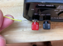
I have an el-cheapo variable voltage DC power supply that I picked up for cheap from Fry's Electronics back when they were in business. I think maybe I paid $25 for it. I have found COUNTLESS number of uses for it while tinkering with electronics / automotive electronics over the years ..... testing LED bulbs, powering radios, testing relays, making LED thingamabobbers for the kid's Halloween costumes, etc....@Jlaa, thanks. I totally get the concept, but would like to ask: what do people usually use as convenient independent source of 12 volts? Do you then attach copper wire or some sort of old cables?
In that case I recommend this one. I have been eyeing it for some time now. The display is very clear (cool WHITE 7 segment LED) and it goes up to 300watts!!! (not really sure I will ever need that much power...) These came out on ali-express a few weeks ago but shipping costs are outrageous since they ship directly from across the ocean.
This is very cheap and clever as well!I use a makita 12VDC battery
Multimeters almost all take banana plugs --- they take both the "Shielded with plastic" kind of banana plugs and the "Unshielded" kind.Do you guys have/use a similar set of leads with your 12v power supplies? These are for multimeters, so they won't fit power supplies that, on a quick glance, require banana plugs.
Just tape some wires to the 9v battery. If you feel like spending $4, buy this below. But honestly, when you insert the wires into the N40 socket, you're just touching the stuff for a second or three just to see what lights up.Say I want to use a 9 volt battery, is there a set of leads that would neatly connect to it AND securely plug in a pin of an N40 connector? Or is using a speaker cable is as best as it gets?
This: ^^^Just tape some wires to the 9v battery. If you feel like spending $4, buy this below. But honestly, when you insert the wires into the N40 socket, you're just touching the stuff for a second or three just to see what lights up.
I think this means you have a butchered x6/1. The center vent no longer lighting up might be a red herring …. But the fact that NOTHING lights up when energizing 58D means you have a break/cut in the wiring for x6/1.I also powered 58D with a 9 volt battery (car battery and everything else was disconnected). Not a single light of ANY kind lit up. Total darkness.
@Jlaa?![]()
There is no aftermarket alarm on my car currently and there wasn't any when I bought it in the summer of 2014. Illumination issue was there from day 1 of my ownership. I'm guessing when the alarm was "deactivated", somehow it took illumination with it. Likely illumination was working when the alarm was installed or the owner of the car would have noticed and taken it back.... or not...That was a messy installation of an alarm system. I cringe any time I see this stuff, as it's often difficult to restore back to factory condition.
It could be responsible for your illumination woes, if they hacked into the blue/gray Holy Grail wires you have been chasing.
![]()
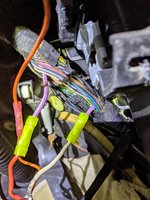
In my search for X6/1 I dropped 2 panels under the steering wheel/over driver's feet and observed this hell:
View attachment 131311
I believe that the dog is berried here. This sheath full of wires goes from around gear lever towards instrument cluster:
View attachment 131313
View attachment 131312 View attachment 131314
View attachment 131315
What the hell is this mess:
View attachment 131316
@Jlaa, you're Moses and I'm a Jew...
In that thick sheathing of wires, only a fat - all other cables in that sheath are skinny - purple/white cable was tapped into. Any idea what this cable "does"?
View attachment 131317
OK let's take it one step at a time since you are new to electrical stuff. Let's delete stuff one by one --- going from least-likely-to-impact to more-likely to impact.@Jlaa and @gsxr, what's the correct way to go about cleaning this up? Just start chopping away at a obviously aftermarket stuff or is it possible this might have unintended consequences?
I'm itching to reconnect into a direct path thick purple/white cable, cutting orange one from the loop? Should I try? I've zero experience tinkering with electrics, so I need some basic guidance and encouragement...