A short update. Note, I removed about 4" of wire on both the leads to the fan and also from the high speed (temperature relay) because the insulation had been overheated and had become brittle and no longer pliable. I removed enough to a point where the insulation was in good shape.
To make my repair... I used non-insulated butt joint connectors with high quality marine wire. The leads to the high speed relay is 12 gauge and those to fan are 14 gauge.
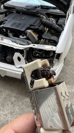
I bought some fiberglass impregnated wire heat sheathing to protect the new wiring along with some high-temp, adhesive-lined shrink tubing to keep the ends from fraying. I also used thick wall, adhesive lined shrink tubing over the (non-insulated) butt joint connections, too. You can see the finished product and a shot of the new resistor where I was testing the AC pressure triggered (low speed). The resistor drops voltage at the low speed to very near 10V (see shot of DVM).
I installed the new resistor because the connector studs were badly corroded so that the threads were no longer serviceable (as if badly galled). I found it on ebay for about $35 shipped.
Finally, I included a shot of the fiberglass sheathing made by Davlyn.
The connectors, shrink tubing, sheathing are all available from McMaster.com
Doug
One more note: I used some high temp copper terminal grease to hopefully keep the terminal ends of the resistor from corroding prematurely or from galling. With luck, I won't need to address this again for a long time.
A second note: I routed my wires a bit differently from the factory with the aim of keeping their high temperature exposure as minimal as possible.
Wow, that's an exquisite looking repair! Nice work. Here's what I wanted to rant on earlier and couldn't. There are some "off label" use prescriptions here in my post, so caution is advised and YMMV:
First here's what actually goes wrong with these resistors: They were mounted in that awkward position that causes all of the heat from that glowing! (yes, look at it in the dark) resistor element to rise upwards over the upper wire termination. This extreme thermal exposure with resultant expansion and contraction causes the threaded attachment to eventually loosen. The loose connection eventually gains resistance to the point that it overheats and burns. This heat also travels along the copper, causing the insulation to burn, which in turn also releases corrosives that infect the termination. The syndrome continues unabated until the connection finally fails and/or the wire breaks.
Two things hasten this process along: The first and most common is that many, if not most of these cars have fan clutches that haven't worked correctly, if at all, since the day the car was built. This caused the auxiliary fans to work almost constantly in a futile effort to cool these lumps off.
Note that if the air conditioning compressor is engaged, the auxiliary fan low speed is usually switched on in a very short time as the refrigerant pressure rises to above 16 bar shortly after start up on a summer day. That is all good. That's why the auxiliary fans are there. They protect and enhance the air conditioner in those conditions where the refrigerant pressure is high, the engine fan is idling (not yet heated up enough to engage), and the vehicle is at low speeds or stationary. In the cars with inadequate fan clutch action, (remember, that's a lot of them), the auxiliary fan low speed was switched on in almost any operating condition whenever the ac compressor was engaged, so that terminal junction got a lot of heat a lot of the time. It didn't stand much chance of survival. Also not surviving this abuse were the low speed auxiliary fan fuses which were either 15 or 16 amp depending on which of the several wiring and relay arrangements that these cars had. Regardless of that and on the subject of fuses, only the Germans would fuse a circuit with a fuse having a capacity only slightly above the current passed through a correctly functioning circuit so that the fuse is frequently overheated and cracks incessantly in hot climates just from the constant thermal cycling. Hello poor ac performance and short lifespan of the high pressure ac componentry including poor Mr. Kompressor. Also, hello such concoctions as the "cool harness" causing the high speed auxiliary fans to work incessantly while duty cycling off the ac compressor to prevent high temperatures, the engine temperature in this case, not yours. The various inoperative fan clutches and low speed auxiliary fans running around out there are why people think these things are just the cat's ass.
WARNING, AUCHTUNG! An "Off label use alert" is in effect for all of the following: You are free to agree or disagree. I've been through these circuits 6 ways from Sunday and have at least 20 years of real world "testing" experience for the advice I offer below. But be warned that it is "approved" by no one, and "tested and verified" by no laboratory or engineer! If you do what I suggest and your car and whatever it is parked in burns to the ground, I KNOW that none of this advice caused it, but still don't tell me about it because I won't care, because as I said, I know this didn't cause it. There, you've been warned.
Now here's what I advise:
For all 107, 123, 126, and 124, If you have a red ceramic 16 amp auxiliary fan fuse in your fuse box [fuse D on the 124], replace it with a blue 25A fuse. It will stop chronically cracking putting thousands of dollars of your refrigeration system at risk. If you develop an actual high current consumption situation, it will burn open as it should and protect the wiring. [Note: This applies to non-V8 models of the 124 chassis. The 400E/500E do not use fuse D as the power feed for the twin auxiliary fans.]
[The pre-facelift, 1992-1993 USA model year 400E/500E have an external 30A strip fuse, typically located behind the brake booster. This 30A strip fuse feeds the single large fan relay K9. See attached image/screenshot with schematic from ETM.]
For facelift (1994-95 USA model year) E420/E500 only: If you have a blue 15 amp blade fuse in the blue low speed auxiliary fan relay (K9/1), replace it with a yellow 20A fuse for the same reason stated just above.
[The high speed relay (K10) may have either a 30A or 40A fuse. See attached FSM ETM PDF; note the schematic differs between -->1993 and for 1994-->.]
The other reason that these resistors cook and fail is that MB kind of mistakenly (IMO again) thought this resistor a hazard early in the V8 124's lifespan. The hazard (ok, usually just some smoke) was actually caused by an aesthetic measure: The cramped quarters in the V8124 caused them to locate the alarm horn in plain sight right there between the brake hydraulic unit and the headlamp. Someone at MB obviously thought that this rude and often corroded bright metal clashed with the acres of black plastic surrounding it. They therefor fashioned a black plastic trim ring that fitted around the circumference of this alarm horn there by making it blend in better with the rest of the black plastic. Low and behold, this plastic ring would get all squidgy from the under-hood heat (remember those fan clutches?), and fall off the alarm horn. Then where would they land? Right on that hot auxiliary fan resistor! How you like that, Smokey?
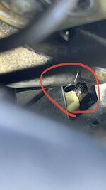
In response to this, did they have us remove the trim ring from the ATA horns? Yes they did. Then they also built in at the factory, or had us retrofit a freaking sarcophagus around that damn resistor! That's why most of these cars have an additional perforated heat shield around these things. It was yet one more thing that tried to kill these overworked resistors and their associated connections. Many of these shields are missing because technicians recognized them for the additional menace as opposed to safeguard that they actually were and they often didn't seem to find their way back onto the vehicles. So here's another off label use. Make sure there's nothing near that resistor, and that anything that could find its way to it, such as a unsecured wire, is properly secured in a position well away from the resistor. Then, assemble the resistor such that it has no additional covering. IMO, it should look exactly as Doug has it in that picture. No less, definitely no more.
Here's another "off label" modification: Let those puppies breathe! Not those puppies, Andy. I'm talking about these resistors. This is very easy to do with the headlamp out, and still doable with the headlamp installed. Using a die grinder, Dremel, or the like, cut a ventilation opening in lowermost vertical portion of the surround shell of the left air guide, just forward of and slightly below the resistor. Here's a few pictures. Expand the pictures and you can easily see the hole, along with my fickle finger through it just in case you can't:


There is already a guide for you right there, as the USA cars prior to '94 have a blanking plug or a knockout plug in that very place that you need to open up, and the Euro cars / USA '94 and later cars have the ventilation hose for the headlamp housing passing through this hole. Make sure that this ventilation hose is still in place after you add a resistor vent hole, as its purpose is to prevent the overpressure that may exist in these air guides when the vehicle is at speed from entering the headlamp units causing dirtiness and condensation. You Euro lamp fitters removed these blanking plugs and installed the vent hoses for your lamps, didn't you? I bet you will now...


")


 . Now, my low speed fans don’t work and I can’t have A/C.