• Hi Guest !

    Welcome to the 500Eboard forum.

    Since its founding in late 2008, 500Eboard has become the leading resource on the Internet for all things related to the Mercedes-Benz 500E and E500. In recent years, we have also expanded to include the 400E and E420 models, which are directly related to the 500E/E500.

    We invite you to browse and take advantage of the information and resources here on the site. If you find helpful information, please register for full membership, and you'll find even more resources available. Feel free to ask questions, and make liberal use of the "Search" function to find answers.

    We hope you will become an active contributor to the community!

    Sincerely,
    500Eboard Management

How to add a good Alpine 6 CD changer to your Becker 1432 without rewiring ANYTHING

I will take pictures tomorrow, although it will not be that clear to figure it out. In the meantime I will explain:
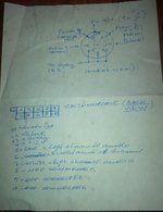
- from the front radio (Becker 1432) there is a 8-pin DIN cable that runs to the back, in the trunk. It was installed at the factory. In the trunk, I connected it to the MX3192, the female socket that has a silver dot.
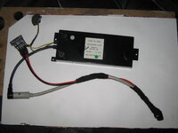
- from the second female socket of the MX3192 I installed an 8-pin DIN Mercedes cable that goes to the amplifier. At the amplifier is connected to the 8-pin female socket (there is also a 6-pin socket that is not used).
- the MX3192 has ab 8 inch cable that ends with a 8-pin DIN male connector. The CD is connected to it with a 8-pin DIN female connector. The female 8-pin is on a cable that I made myself and is shown in post #96. This cable feeds power to the Alpine CD separately thru two wires and doesn't supply power to MX3192, per answer from post #92.
- in the trunk the power cables are supplying 12V to the amplifier, the MX3192 and the CD shuttle (like I ust mentioned, from the shuttle 12V is NOT fed also to the MX3192).
That all sounds correct to me. Be1432 to the silver dot. Then the no-dot female din to the original 8 pin din on the tuner/amp module ... unless the wires themselves are wonky? Are you using the black headed din cable with the no-dot female din on the 3192?

I will check out your pictures and also test my own with a multimeter.

I read the previous posts and I cannot see a flaw in the way I connected my components. The fact that @Jlaa gets identical messages with identical results on his radio when trying to play disks 2-6 makes me think this is more of a software compatibility between components rather than me having things connected wrong.

Also I am seeing on the internet people talking about "adapters" or "interfaces" in order to play aftermarket CD shuttles like Alpine with OEM radios. That makes me think that the addition of the Alpine 6-CD changer to an OEM system may not always be a plug and play job. The type of messages and the system's behavior make me believe the Alpine doesn't get/understand the commands coming from the radio.

I did read somewhere that the ancient MBUS protocol is really really slow —- like it is only 250 baud, and it is half dupex. Have you been ableget a hold of @Dbreid? I know he’s still around here and he got it to work with a real alpine changer ....

also, when do you receive the yatour?
 
Here are the pictures:
IMG_7458.JPGIMG_7462.JPGIMG_7461.JPGIMG_7463.JPG

The setup will be complete after I figure everything out, but right now is at a stage where it should be fully functional.

That all sounds correct to me. Be1432 to the silver dot. Then the no-dot female din to the original 8 pin din on the tuner/amp module ... unless the wires themselves are wonky? Are you using the black headed din cable with the no-dot female din on the 3192?
Yes, as seen in the mirror the cable from the front goes to the silver dot. The one-end black cable goes from 3192 (barely seen in the mirror because is black on black) to the amplifier (where is connected with the grey end).

I did read somewhere that the ancient MBUS protocol is really really slow —- like it is only 250 baud, and it is half dupex. Have you been ableget a hold of @Dbreid? I know he’s still around here and he got it to work with a real alpine changer ....
No, I did not try, but I just sent him a PM asking to look at the last posts, maybe he sees something or remembers something.

also, when do you receive the yatour?
Well, this is another story: there was only one Yatour in the US with a cable with 8-pin DIN cable end. Two days after buying it on Ebay, the seller cancelled my order (item not available anymore, or not found). I placed another order in China, but to get it here will take at least a month. I am not in a big hurry and I can wait doing other things on the car, I am more interested in knowing that it works, but that does not appear to be in the cards for me. I also ordered another cable with black end from Becker, just in case.

Regardless of the final result, I do appreciate all the help offered.
 
Last edited:
Hey all. I AM still around here, but I did this quite a while ago. I will say that I used pretty much all "OEM" stuff (I am including Alpine as OEM here). I didn't splice any wires or anything like that. I can look at my setup and answer questions as needed, of course. But without laying in my trunk and following wires, I don't remember off the top of my head.

Lemme go get the car and see what I can see.
 
I will say that I used pretty much all "OEM" stuff (I am including Alpine as OEM here). I didn't splice any wires or anything like that. I can look at my setup and answer questions as needed, of course.
Thank you for jumping in to help. The only splicing is on the cable from the (small black brick) 3192 to the Alpine to supply the voltage. Everything else is OEM with no modifications. I would have used a cable with no modifications, but in earlier posts the adapter cable MBZ/E-ALP came into discussion as being needed to supply 12V to what will be connected to the 3192 (in our case is the Alpine).

@Dbreid I am interested in only one thing/pictures please: What cable(s) (8-pin DIN, 12V, etc.) do you have between the Alpine CD player and the small black MX3192? Thank you.
 
Last edited:
Yes, as seen in the mirror the cable from the front goes to the silver dot. The one-end black cable goes from 3192 (barely seen in the mirror because is black on black) to the amplifier (where is connected with the grey end).
.....I also ordered another cable with black end from Becker, just in case.
@liviu165 , thanks for sending the pictures. To be honest, your picture of the black head cable that connects between the tuner/amp and the mx3192 looks funny to me. It should have black head and a thick beige jacket. You can see my cable in post 9. However, the cable you are using seems to have a black head and a thin yellow jacket. Am I looking at your pictures correctly? This immediately jumped out at me . Maybe I am looking at the wrong thing.

810CB01F-552B-4368-984E-BDBC43A989EF.jpeg
 
You are looking at the power cable (yellow and brown wires). The cable you are referring to is next to it and starts to show up at the edge of the mirror, under your red lines. It is a Mercedes cable, just like yours.
IMG_7461_1.jpg
 
I didn't splice any wires or anything like that. I can look at my setup and answer questions as needed, of course. But without laying in my trunk and following wires, I don't remember off the top of my head.

Lemme go get the car and see what I can see.
Thank you for your offer to help @Dbreid , but I don't think you need to check your setup anymore. At a closer examination of post #1 I noticed in one of your pictures that `the 8-pin connector cable appears to had been spliced to insert 12V (my yellow arrow), I can even distinguish a black zip tie. Of course, after so many years it would be hard for anybody to remember. :)

[500Eboard] 34.jpg

@Jlaa : Would be possible please to examine your (original ) 8-pin cable with the two leads and post the electrical diagram of the cable? Regardless of what I will end up using (CD changer, Yatour or anything else) I will still need to make that cable. I don't know if the previous cable I made is my problem, but because the MBZ/E-ALP cable is NLA I am thinking that its electrical diagram will be an important reference here and help others in the future. Thank you.
 
Thank you for your offer to help @Dbreid , but I don't think you need to check your setup anymore. At a closer examination of post #1 I noticed in one of your pictures that `the 8-pin connector cable appears to had been spliced to insert 12V (my yellow arrow), I can even distinguish a black zip tie. Of course, after so many years it would be hard for anybody to remember. :)

View attachment 105696

@Jlaa : Would be possible please to examine your (original ) 8-pin cable with the two leads and post the electrical diagram of the cable? Regardless of what I will end up using (CD changer, Yatour or anything else) I will still need to make that cable. I don't know if the previous cable I made is my problem, but because the MBZ/E-ALP cable is NLA I am thinking that its electrical diagram will be an important reference here and help others in the future. Thank you.
Hi @liviu165 , which 8-pin cable with two leads are you talking about? Are you talking about this one in post #90?

[500Eboard] 1591072233799.png
 
Yes, that's the one I am talking about, thank you. There has been talk back and fourth about that cable, I think a diagram would be best.
 
Yes, that's the one I am talking about, thank you. There has been talk back and fourth about that cable, I think a diagram would be best.

@liviu165 - ask and ye shall receive.

It looks like your suspicions are correct - this cable is more complex than we thought! This time around when I tested the cable, I fashioned little wire ends to go into the female holes of the cable --- last time I used my probes and the probe tips were too big to reliablly test the electrical connectors.

Every pin in the diagram that has a color associated with it is connected to every other pin with the same color.
As well, note that the white dot Z connector shows that it is connected to TWO pins (two other white dots) on the cable ---- my previous testing with the probes was unreliable and therefore missed one of the pins. My apologies!

Please post back and let us know how you get on....

IMG_8466.png
 
Last edited:
Thank you for quick response, @Jlaa. Your picture offers some clues but it also generates new questions. If is fine with you I suggest we take it offline to figure the cable and then I will post an electrical diagram of that cable. I will PM you. Thanks.
 
Based on the above picture I made the electrical diagram of the cable. I would like stress that I never got to make the cable using my diagram, so I have no irrefutable proof that it works. However, I am posting the diagram I came up with in case somebody would like to give it a try and for the group's benefit will tell us if it works or not.

The reason I never made the cable is because I decided to go a different route: I used Mercedes CD changer MC3196NA and made an adapter cable between MX3192 and the CD changer. I had some very good reasons to go that way and I got excellent results, but I will offer the details in the future in a different thread.
 

Attachments

  • ALPINE-MBZ.JPG
    ALPINE-MBZ.JPG
    59.6 KB · Views: 65
Last edited:
@liviu165 -- so you attached a MC3196NA to the MX3192, all driven by your BE1432 right? I didn't know this was possible! I know the MC3191 could be driven by the MX3192, but didn't know about the MC3196NA.
 
@liviu165 -- so you attached a MC3196NA to the MX3192, all driven by your BE1432 right? I didn't know this was possible! I know the MC3191 could be driven by the MX3192, but didn't know about the MC3196NA.
Yes, you are correct: the BE1432 with a MX3192 can drive a Mercedes MC3192NA or an Alpine CHM-S620. In fact I also tested with great success the Alpine CHM-S630 too. They all work fine and with the same adapter cable I can use either one on MX3192. I will explain that in more detail with pictures in a thread of its own (and add a link here).
 
Last edited:
Hi liviu 165, I have exactly the same issue as you. I fitted the MX3192, purchased an Alpine player, built a special double female din cable with earth and power. Head unit can see the Alpine, knows it is a 6 stacker and logically loads discs 1 to 6. Alpine has power and the shuttle can be ejected and inserted. All CDs are commercial CDs, but no playing and no sound. Did anyone get back to you with a resolution. Amp has been rebuilt, casette and radio work properly. Previous Becker wouldn't play even though I spent $300 getting it overhauled. These things are a nightmare and a money pit but keen to get a resolution. Anyone? My Alpine is CHM S630.
 
Hi Andy, I was able to successfully build a cable to communicate with the CD player, but my cable ends with a Mercedes connector. I will explain at the end of this post.

I tried to build three versions of those cables and not all worked at that time (probably due to my limited knowledge at that time):
  1. Round 8-pin to Round 8-pin DIN both ends. That would be a direct plug cable, no modifications to existing components needed. This is what you need.
  2. Round 8-pin DIN one end and 8-pin flat connector of the CD player (this is a cable that at one end uses the connector inside the CD player, picture # 1 below). You'd have to open the CD player and build a cable directly from the board's connector to the MX3192. I would not go that route if I were you.
  3. Round 8-pin DIN connector to Mercedes 2-row connector (used in Mercedes CD players like MC3196NA, picture #2). This complicates the issue even more, I do not recommend you go this way.

In the end I chose solution #3 because it was much easier to build and I had about 6-7 CD players to play with. I built myself a longer cable as the one shown in the last picture (I bought the defective CD only to get that cable which in the end gave me the answer). Also after opening the Alpine and Mercedes CD players I noticed that I can combine a Mercedes cable with an Alpine board. That's how I was able to test the Alpine 630 and it worked.

Anyway, your case is much easier: you need to have a cable built as shown in post #110. What I did is more complicated but it worked very well for me. Did you try to have that cable shown in post 110 built?

IMG_20200601_225353.jpgPlug3.jpgIMG_20200619_211920.jpg
 
Hi yes I built that cable specifically as per the directions in post #86 and #90. Prior to that with just the double female din the CD changer was getting no power. I piggy backed the power and earth as per #86 and #90. Now the changer gets power and the shuttle will load and eject, light comes on etc but the player does not play. Player is correctly identified by the head unit as a 6 stacker and load 1 through 6 appears. First CD loads, but there is no sound and as far as I can tell from the noise at the stacker it doesn't appear to be spinning up. My colleague in Sydney has done the same steps for his and his issue mirrors mine.
 
Hi yes I built that cable specifically as per the directions in post #86 and #90. Prior to that with just the double female din the CD changer was getting no power. I piggy backed the power and earth as per #86 and #90. Now the changer gets power and the shuttle will load and eject, light comes on etc but the player does not play. Player is correctly identified by the head unit as a 6 stacker and load 1 through 6 appears. First CD loads, but there is no sound and as far as I can tell from the noise at the stacker it doesn't appear to be spinning up. My colleague in Sydney has done the same steps for his and his issue mirrors mine.
Post #86 and #90 were the early investigations, but have since been superceded by post #110. Post #110 is the most accurate representation of the cable that needs to be built. #86 and #90 were missing some of the pins for power/ground that were found in #110.

As well, post #86 assumed that the data/audio pins in the 8-pin-DIN connector were straight-through-mapping, which was not the case, as proved by post #110.
 
Last edited:
Yes ,That would be Me the colleague in Sydney ( Chris) , Hi Andy .
I have made that Cable today as well , it works . The only issue i have is that the Sound is very Low , either with the Yatour or Cd Changer . I have the CHA-620 & CHA-634 ,booth same issue . Radio is Sound as normal . To hear anything by selecting CD on Radio ,i would need to go Full Power on Radio Volume which is not a good Idea (it got me twice already) . I'm coming to think that the Fader Switch on the Middle console has something to do with this .
The MX3192 works as it should - Tuner functions - Rebuild AMP - Radio is perfect .
Great Thread here Guys .
My Lazy standing in the Garage Queen is 92 W140 600SEL Lorinser .
I made this Cable after Andrew confirmed Success Duplicating it .
Posted as Insert in Post #112 by liviu165 above .

ALPINE-MBZ.jpg
 
Last edited:
@Merc-S600, I am not familiar with your car model, but if the radio setup is the same (and I believe is the the same) as mine, then the sound volume to the fader should to be the same because it comes from the same source (the Amplifier), no matter where the signal arrives to the amplifier from (the radio-cassette or the CD player). For that reason I don't suspect your problem is the fader switch, I suspect is more upstream.

Based on your description I rather suspect that your issue might be caused by something specific to the CD player, something that is not used by the radio or the cassette player. I suspect that that "something" is the MX3192 because that's the component that is used only by the CD player or possible the cable you made. Those cables are no very easy to make because of the small area to work with. Actually one of the ones I made had a discharge to ground, a defect that took me a while to figure out.

@Jlaa : In your picture in post 110, you don't show the middle pin of the left socket connected to anything. Can you please verify that? My notes show that in the cable I am using, that pin (#8) of the socket connected to the MX3192 is actually the signal ground and is connected to the cable's shield and ground. Although not in a final version to be presented here, below is the original note I followed in making the cable that is now in my car and works perfectly. My cable is a replica of the one in the 2nd picture, except that is almost 4 feet long.
 

Attachments

  • IMG_20200626_094320.jpg
    IMG_20200626_094320.jpg
    769.8 KB · Views: 39
  • Alpine2.jpg
    Alpine2.jpg
    39 KB · Views: 30
Last edited:
@Merc-S600, I am not familiar with your car model, but if the radio setup is the same (and I believe is the the same) as mine, then the sound volume to the fader should to be the same because it comes from the same source (the Amplifier), no matter where the signal arrives to the amplifier from (the radio-cassette or the CD player). For that reason I don't suspect your problem is the fader switch, I suspect is more upstream.

Based on your description I rather suspect that your issue might be caused by something specific to the CD player, something that is not used by the radio or the cassette player. I suspect that that "something" is the MX3192 because that's the component that is used only by the CD player or possible the cable you made. Those cables are no very easy to make because of the small area to work with. Actually one of the ones I made had a discharge to ground, a defect that took me a while to figure out.

@Jlaa : In your picture in post 110, you don't show the middle pin of the left socket connected to anything. Can you please verify that? My notes show that in the cable I am using, that pin (#8) of the socket connected to the MX3192 is actually the signal ground and is connected to the cable's shield and ground. Although not in a final version to be presented here, below is the original note I followed in making the cable that is now in my car and works perfectly. My cable is a replica of the one in the 2nd picture, except that is almost 4 feet long.

@Merc-S600 @liviu165,

Excellent progress!

I just went and retested the cable this morning - no change in the diagram. The middle pin on the left socket is not connected to any other pin on the left or right, nor is it connected to the shield part of the connector on the left or the right.

That said ..... might as well try connecting that pin to cable shield/ground? Because if that pin is indeed signal ground then a floating signal ground could possibly cause reduced volumes.
It would also be interesting to hear about the experience of @AndyBlundenInOz after he remanufactures the cable.
 
Last edited:
Thanks for the Replies .
I tested & tested the cables wiring over & over again today , it appears to be perfect on every Pin with the Diagram provided . The System in the W140's (the early once) consist of Radio Becker Grand Prix 2000 (BE1432) , then the Tuner in the Trunk which has the Line for the CD Changer (BE 980) and the AMP . Somewhere i was reading that a System with the Bose" AMP system ,that when switching from Radio to CD , the frequency would lower the output to Half it's Power due to the AMP trigger wiring , i doubt it is the case but it got my attention . If i find the Article i post it here .
 
Ok , found it .
Just a few lanes from that Thread .

__________________________________________________
" A couple of notes: the aftermarket HU will require you hooking up the amp turn on wire instead of the antenna power wire since the stock system requires both. The stock wire allows the antenna to go up AND power up the amp. If you hook the ant. wire only, then the Bose amp will power only during radio operation, not CD or other music sources.
___________________________________________________
 
@Merc-S600 @liviu165,

Excellent progress!

I just went and retested the cable this morning - no change in the diagram. The middle pin on the left socket is not connected to any other pin on the left or right, nor is it connected to the shield part of the connector on the left or the right.

That said ..... might as well try connecting that pin to cable shield/ground? Because if that pin is indeed signal ground then a floating signal ground could possibly cause reduced volumes.
It would also be interesting to hear about the experience of @AndyBlundenInOz after he remanufactures the cable.

Hi all as we chase down this problem. I went ahead and made the cable as per the diagram and I report that it works as expected with no volume loss at all and the changer working as expected (I do not have the volume drop as reported by Chris) Chris and I have spoken on the phone and to eliminate problems systematically I am going to duplicate another cable for him, test it in my car and verify that it works and then send it on to him once I confirm that it is ok. Standby. We are progressing and thanks for all the help guys. BTW my car is a 1992 W140 500SEL with Bose amp (rebuilt recently by Lenny in the USA)
 
Hi all as we chase down this problem. I went ahead and made the cable as per the diagram and I report that it works as expected with no volume loss at all and the changer working as expected (I do not have the volume drop as reported by Chris) Chris and I have spoken on the phone and to eliminate problems systematically I am going to duplicate another cable for him, test it in my car and verify that it works and then send it on to him once I confirm that it is ok. Standby. We are progressing and thanks for all the help guys. BTW my car is a 1992 W140 500SEL with Bose amp (rebuilt recently by Lenny in the USA)
This is so great to hear and I am very happy for you guys! This thread is so long and so involved and spans many years —- but what is really nice is that with persistence and determination the set up works and can be duplicated!!
 
I too am very glad to hear you got it working, I had my share of frustration too trying to figure it out.

I am looking back at this thread and I am thinking that actually it has nothing to do with the title. It says is about connecting the Alpine CD "without rewiring ANYTHING" but we are talking big time about making specialty cables. Go figure!
 
Last edited:
I too am very glad to hear you got it working, I had my share of frustration too trying to figure it out.

I am looking back at this thread and I am thinking that it actually it has nothing to do with the title. It says is about connecting the Alpine CD "without rewiring ANYTHING" but we are talking big time about making specialty cables. Go figure!

Yes correct the point at which everything changed for the better was when someone figured out that the wiring was not straight through as per the original din plugs. The circuit diagram in post #112 changed everything and I've now made the spare cable for Chris and we shall see what happens this week when he gets it. Mine works perfectly and I hope after this that his does too. Thanks all
 
I've now made the spare cable for Chris and we shall see what happens this week when he gets it. Mine works perfectly and I hope after this that his does too.
Please let us know of the outcome. What did you use for the cable, the picture from post 110 or the diagram from post 120? In theory they should both be the same (the diagram was made after the picture in 110), but I never got to make a cable using the diagram. I just want to make the diagram is correct.

I am thinking that after we confirm that we found a way to connect the Alpine and have it working maybe we should start a new thread with a more appropriate title and the right info from the beginning. This thread does have valuable information too, but only after @ 100 posts or so.
 
I am thinking that after we confirm that we found a way to connect the Alpine and have it working maybe we should start a new thread....

Right on! I think it should be a HOW-TO --- right El-Guapo, El-Honcho, Mister-Emp, @gerryvz? 😇


This thread does have valuable information too, but only after @ 100 posts or so.

Well to be frank the first couple of posts were immensely valuable and super helpful, especially with the MX3192, the cables, etc. It is only because the adapter cables became completely unobtainable at some point between 2013 & 2020..... I mean those adapter cables became even harder to find than w124.036 500E headlight lenses (which ironically none of you three @liviu165 @AndyBlundenInOz @Merc-S600 are familiar with because you have taken this thread and adapted it to w140s / w126s...) .... and it is only because those adapter cables became impossible to find that this thread took a completely orthogonal track and turned into a "reverse-engineering some special cables" thread.... 😂
 
Last edited:
I agree that the first two posts were extremely valuable and we could not have done it without the MX3192 information.
 
Please let us know of the outcome. What did you use for the cable, the picture from post 110 or the diagram from post 120? In theory they should both be the same (the diagram was made after the picture in 110), but I never got to make a cable using the diagram. I just want to make the diagram is correct.

I am thinking that after we confirm that we found a way to connect the Alpine and have it working maybe we should start a new thread with a more appropriate title and the right info from the beginning. This thread does have valuable information too, but only after @ 100 posts or so.

For the benefit of others, the Diagram I used is in post #112 and my method was to find a double female 8 din cable, cut it in the middle and then join by rerouting connections as per the diagram. I used a multi meter to identify the colour wire for each pin and wrote the colour on the diagram. Then I worked from left to right i.e. start at pin one Id the colour and then find out what pin it is attached to on the right and ID that colour. I will offer you several hints here. Soldering at the plug is too hard, so cutting a cable and re routing is way easier. I used a micro soldering iron (only 10 Watt) it has a very small tip and doesn't cause the other wires or the shrink wrap to get hot. Secondly when I solder I first slide the shrink over the longer wire and then hold that wire with a pair of pliers to absorb heat and prevent the wires from heating and the shrink wrap from tightening. The smaller soldering iron alloys a very quick and precise solder join. Then I slide the shrink over and re heat. Repeat for all wires. Ensure that the copper earth is rejoined, and also ensure that the foil shield is wrapped to reduce hum. Then tape the whole area of the joins firmly with insulation tape.
 
I thought of your solution too but I decided not to go that route because some specific cables are supposed to be shielded and this solution offered the wrong insulated cables. The shielded cables are the two audio signal channels and the BUS signal (each with its own shielded cable). So, the OEM cable is having two shielded cables inside the main shield. Soldering at the plug proved to be hard for the first plug soldered, but I got better at doing it as I kept on soldering.
 
I thought of your solution too but I decided not to go that route because some specific cables are supposed to be shielded and this solution offered the wrong insulated cables. The shielded cables are the two audio signal channels and the BUS signal (each with its own shielded cable). So, the OEM cable is having two shielded cables inside the main shield. Soldering at the plug proved to be hard for the first plug soldered, but I got better at doing it as I kept on soldering.

I too was worried about hum etc but the solution I created has no interference and is quiet. Luckily.
 
Hello, does anyone know if I can use this Yatour module instead of buying an emulator and a separate Bluetooth module? What other connections will I need to make sure it gets power?

Yatour YT-BTA
 
Hello, does anyone know if I can use this Yatour module instead of buying an emulator and a separate Bluetooth module? What other connections will I need to make sure it gets power?

Yatour YT-BTA
That won’t work with a BE1432 unless you get an MX3192.
 
I do, I have a working CD changer I can cannibalise for the MX3192. I guess my question is: doesn’t the DIN connection already provide power? The “USB charging port” is throwing me off.
 
I do, I have a working CD changer I can cannibalise for the MX3192. I guess my question is: doesn’t the DIN connection already provide power? The “USB charging port” is throwing me off.
I have never used the USB port on the Yatour. i think that ebay ad is wrong. The Yatour USB port is for jacking in a USB memory stick (from the instructions) - I do not believe the USB port is meant to charge anything.
 
That’s what I thought after looking back at a listing for the M07. Thanks for clarifying, I think I will try my luck with this unit.
 
UPDATE:
Andrew B did make & send me the Cable plus additional Becker cables for further testing . Same result with just barely any Sound yet at full volume on radio , the cable i made was ok as well (just for the record lol) .
Purchased another Tuner (pictured below) in the trunk which has yet to arrive .
I suspect that the Previous Owner ,since he started selling parts of this 600 i have ,that the Tuner might be either defective for the Cd function Chanel or the incorrect one all together as i have 1 power cable leading to no were except looking at the lengths , somewhere near the Tuner Section .
This one has a little "LINE OUT" extra connection at the back to which i have no idea what that is for or were or what it gets connected to ,maybe someone here has more info on it .
Pic attached of the part i bought . Red square is that Line Out ,(?) .
 

Attachments

  • Mercedes 001-820-96-89 BE1432 SL600 1432.jpg
    Mercedes 001-820-96-89 BE1432 SL600 1432.jpg
    31.3 KB · Views: 12
Hi @Merc-S600, yes, in USA market 1992 and 1993 500Es, that line-out module has three pins -- left, right, and common audio ground. From that line-out module, the signal goes to the fader wheel in the cabin. From the fader wheel in the cabin, the signal then goes to the two amplifiers in the boot. Does your S600 have the fader wheel in the cabin and two amplifiers?

1602736515820.png
1602736805124.png

1602736835277.png
 
Hi Jlaa .
Thanks for the Reply . Yes mine has the Fader Wheel which i strongly suspect to be the problem , 1 AMP in trunk with of course the Tuner to it .
 
Hi Jlaa .
Thanks for the Reply . Yes mine has the Fader Wheel which i strongly suspect to be the problem , 1 AMP in trunk with of course the Tuner to it .
Hi @Merc-S600 you are welcome. OK I'm not sure how S600s were configured, but in the USA, w124s often times had two variants of the BE1432-based system.

  1. The SOUND SYSTEM type, which is what I have, uses TWO amplifiers in the boot. The fader wheel is before the amplifiers, and the fader wheel is fed by the line-out module as mentioned above on the back of the tuner module. The two amplifiers in the boot power all the speakers in the car. The wiring diagrams I posted above are for SOUND SYSTEM type cars. The line-out module is for these types of cars.

  2. The ACTIVE BASS type, which I have provided a wiring diagram for below. This type has ONE amplifier in the boot. (I mention this because you mentioned that your configuration has one amplifier). In the ACTIVE BASS type, the tuner module itself powers the front dash and rear deck speakers, and the amplifier in the boot powers the pair of door speakers. With this type, the fader wheel is a bit convoluted I believe the fader wheel is AFTER amplification. This system is really quite strange and I do not believe this type uses the line out module (but I am not really sure). These systems are notorious for having finicky fader functionality.
1602737483334.png
 
Here is a Diagram . They basically all the same in a way just that the S class W140's only have 1 AMP for earlier once ( 91-94) then later once don't have the Tuner anymore in-between . Makes me wonder if Andrew has the Fader Wheel , he should since i believe he has an S500 . Some call the Fader Wheel the INFAMOUS FADER WHEEL ,must be a reason for that . Mine is a UK import with a lot of extra options to it ,maybe it has also something to do with all this .
 

Attachments

  • 1432_%20system_configuration.png
    1432_%20system_configuration.png
    232.5 KB · Views: 39
Hi @albeee care to show us how you wired it up ?

Also can you control the BT setup from the head unit or do you have to use the iPhone controls ?

Regards

 
@liviu165 asked me a good question tonight about this diagram:

View attachment 104742

He asked me if the Z cable connects to both DIN Female ends or just one end. So I took the cable out of my car and measured continuity w/ the mulimeter. OMIGOSH! The Z cable connectors (+12v and ground) only connects to the OTHER END!

View attachment 104741

@liviu165 that was a great question!!!!!!!! So please make sure that if you are making up your own replica-cable that you introduce power only to one end!!! @JoeyManhattan please take note ---- I know you think that you have 2 busted MX3192s but I wonder if the reason why stuff isn't working for you is because your cable is made incorrectly and powers both ends? I don't remember if you are using a cable that you made up or if you are using a purchased cable.

As a reminder for posterity as well, this is how this cable connects to the MX3192:

View attachment 104743
Thanks for the tip, when I get the car out of storage I’ll look at the cabling and go from there.
 
@Jlaa I got the car out of storage today and tested the cable, it’s wired correctly and still no cd recognition after sitting all winter without a battery. Willing to send one of the MX3192 units for repair but I can’t find anyone that works on them.
 
@Jlaa I got the car out of storage today and tested the cable, it’s wired correctly and still no cd recognition after sitting all winter without a battery. Willing to send one of the MX3192 units for repair but I can’t find anyone that works on them.
I can take a look at it if you would like. I repair similar devices, and have several "parts" MX3192s for spares as well. Let me know.
 
@liviu165 - ask and ye shall receive.

It looks like your suspicions are correct - this cable is more complex than we thought! This time around when I tested the cable, I fashioned little wire ends to go into the female holes of the cable --- last time I used my probes and the probe tips were too big to reliablly test the electrical connectors.

Every pin in the diagram that has a color associated with it is connected to every other pin with the same color.
As well, note that the white dot Z connector shows that it is connected to TWO pins (two other white dots) on the cable ---- my previous testing with the probes was unreliable and therefore missed one of the pins. My apologies!

Please post back and let us know how you get on....

View attachment 105702


I just wanted to post my THANKS to everyone who has contributed to this thread, and to personally thank @Jlaa for his amazing contributions, as well as directing me to this thread.

I just used the Post #110 diagram to wire my own cobbled-together adapter harness w/ a Becker 1432, MX3192, and Alpine CHM-S620 CD Changer, (1992 600SEL) and I am overjoyed to report that it is working PERFECTLY! No weirdness or anything at all to speak of. Couldn't have done it without you guys and this thread. (ok, i probably could have, but I don't have that kind of time!)
 

Attachments

  • IMG_0166.JPG
    IMG_0166.JPG
    940.6 KB · Views: 22
Back
Top