• Hi Guest !

    Welcome to the 500Eboard forum.

    Since its founding in late 2008, 500Eboard has become the leading resource on the Internet for all things related to the Mercedes-Benz 500E and E500. In recent years, we have also expanded to include the 400E and E420 models, which are directly related to the 500E/E500.

    We invite you to browse and take advantage of the information and resources here on the site. If you find helpful information, please register for full membership, and you'll find even more resources available. Feel free to ask questions, and make liberal use of the "Search" function to find answers.

    We hope you will become an active contributor to the community!

    Sincerely,
    500Eboard Management

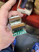
Antenna inspection and board repair.

Simon455

Member
Member
Figure I share this with the group, the power antenna would not go up on my newly acquired ‘92 500e. Simply tested power feeds and ground, all good, removed it, had a look inside the assembly, internal gears and belt drive looked really nice shape, jumped power directly to the motor circuit, verified its operation and mechanism worked really good, pulled out the circuit board and as suspected, found corrosion. Further cleaned it, dropped it off at a local electrical guy that specializes in board repairs.
Had it back in a couple of days repaired, tried it, confirmed operation, works as it should.
 

Attachments

  • IMG_0949.jpeg
    IMG_0949.jpeg
    681.9 KB · Views: 19
  • IMG_0950.jpeg
    IMG_0950.jpeg
    2.7 MB · Views: 17
  • IMG_0955.jpeg
    IMG_0955.jpeg
    1.4 MB · Views: 19
  • IMG_1108.jpeg
    IMG_1108.jpeg
    1.4 MB · Views: 19
Last edited:
Nice! Did the shop tell you what component(s) failed?
I already saw it my self prior dropping it off,
the two big resistors under the rear heat sink had badly corroded feet and separated from the board, input terminals were corroded and one of the pathways looked severely damaged. So it wasn’t really components failure, rather water/moisture intrusion through the mast over the span of over 30 years.
 
I found this thread particularly timely as I have a Hirschmann Auta 6000 control board and determined that mine had a shorted BD438 power transistor and I need help identifying adjacent resistor values to complete my fix.

Car: 1991 420SEL (W126, chassis 126.035), final model year.

I’ve been chasing a dead short and have it narrowed down to the antenna control board. Posting the full diagnostic chain in case it’s useful to anyone else, but my specific ask is at the bottom.

Symptom
Fuse #15 (8A) blows instantly whenever the power antenna is connected. With the antenna unplugged, the fuse holds and everything else on that circuit — interior lights, trunk light, door lights, central locking — works normally.

What I’ve ruled out
• Split the antenna from its harness at the unit, re-fused: holds fine with the harness live and hanging. So the run from the fuse box to the antenna is clear.
• Reconnected the antenna: fuse blows instantly.
• Bypassed the control board and ran the motor directly: motor works fine.
• Mast and drive cord move freely, no binding.

Key detail: when it blows, there’s no relay click, no motor twitch, no delay. Instant. So current never reaches the relay coil or the motor — it’s finding ground at the drive stage.

What I found on the board
Unit markings: mechanism casting 721 075-001, control board 722 398-00.
On the solder side there’s a clearly charred, carbonized area with browned laminate around two adjacent joints. Directly above it on the component side sits a BD438 PNP power transistor (TO-126) bolted to the copper heatsink strip. The mounting nut and heatsink show browning consistent with sustained heat. My working theory is a collector-emitter short in the BD438, which matches the no-click/instant-blow behavior exactly.

Where I need help
I have a bench tech lined up who’s willing to do the component-level repair — desolder the BD438, clean the carbon down to clean laminate, check the pads and traces, and replace. The BD438 itself is easy to source.

The problem is the three resistors immediately adjacent to the transistor. A shorted driver often takes its base resistor with it, so we want to replace whatever’s damaged. But I can’t read the color bands reliably — the copper heatsink throws a warm reflection that pushes everything toward red/orange, and at least one of them is heat-browned.

So: does anyone have an intact 722 398-00 board they could read the values off of? Or has anyone rebuilt one of these and noted the values?
Photos attached — component side showing the BD438 and the three resistors, plus the solder side showing the char pattern.

One more thing I’d welcome opinions on: what killed it. There was some nylon drive cord debris on the spool gear. I’m wondering whether marginal binding over time raised motor current enough to cook the output stage — in which case a new transistor alone would eventually fail again and I should do the gear/cord kit at the same time. Has anyone seen that pattern?

(For reference, I understand these went from a 5-pin connector through end of 1990 to a 3-pin for 1991, so its my understanding that board variants aren’t interchangeable — mine is the 3-pin.)

Thanks in advance. These units are NLA from both Hirschmann and MB, so I’d much rather repair than hunt for a used one.
 

Attachments

  • IMG_5812.jpeg
    IMG_5812.jpeg
    911.1 KB · Views: 5
  • IMG_5810.jpeg
    IMG_5810.jpeg
    1.8 MB · Views: 5
  • IMG_5814.jpeg
    IMG_5814.jpeg
    949.3 KB · Views: 5
  • IMG_5809.jpeg
    IMG_5809.jpeg
    1.7 MB · Views: 5
  • IMG_5790.jpeg
    IMG_5790.jpeg
    1.3 MB · Views: 5
Last edited:

Who has watched this thread (Total: 2) View details

Back
Top