• Hi Guest !

    Welcome to the 500Eboard forum.

    Since its founding in late 2008, 500Eboard has become the leading resource on the Internet for all things related to the Mercedes-Benz 500E and E500. In recent years, we have also expanded to include the 400E and E420 models, which are directly related to the 500E/E500.

    We invite you to browse and take advantage of the information and resources here on the site. If you find helpful information, please register for full membership, and you'll find even more resources available. Feel free to ask questions, and make liberal use of the "Search" function to find answers.

    We hope you will become an active contributor to the community!

    Sincerely,
    500Eboard Management

FYI Beru spark plug wire set ZEF-635

Trae

E500E **Meister**
Member
Hi guys,

I had been chasing a misfire on my 93' 500E for a month. I had replaced spark plugs, caps, rotors, and insulators behind the rotors thinking it might have been moisture build up behind the cap. Car ran fine cold, BUT would misfire as soon as it reached operating temperature.

Then, I started focusing on the suppressors that fit over the spark plugs and the terminals that fit over the cap. Measured each wire for 2,000 ohms of resistance +-10%. Number 8 wire tested a little out of range, so I replaced the terminal and suppressor. Still, I had a misfire after warm up. The wires were a mix of Bremi terminals and Karlyn suppressors. I was not impressed with any of them.

Finally replaced all 8 plug and both coil wires with new Beru wires made in France. Gsxr sent me this link and I am very happy to report that my problem is solved. Select the wires that are specifically E500E because they are cut to the proper lengths. 1992-1993 500E, OR 1994 E500.

If you decide to do this job, Wurth Rubber Care will be your savior and make life very easy when adjusting wires and connecting them to plugs and caps. Many thanks to Gsxr for his excellent pictures and link to these wires.

Also, many thanks to Jono as he told me about Rubber Care and wire numbers to the corresponding cylinders that are listed in the plastic tracks. It would be difficult to do this job without those numbers.

This was my first time to replace wires and it took 4 hours to make mine look like Gsxr's pictures, but I think I could do the job in about 2 hrs. now. I ordered wire markers and clipped them onto the wires BEFORE I started the job by measuring each wire first and labeling them. Made it easier to keep up with the wires.


Link to Beru wires available at PartsGeek:
W0133-1599712 | Partsgeek.com

Update Nov-2022: Beru ZEF-635 is now also available from FCP with lifetime warranty. See post #14 below.


Wurth Rubber Care:

Wurth Rubber Care Silicone Free - Clean, protectect, nourish, and replenish all rubber surfaces—without silicone! Wurth brings the multi-faceted Rubber Care to the US—a versatile, all-in one spray for all your rubber needs. Paint-friendly Wurth ...


Wire markers: Edit- these wire markers will expand with heat and slip around on the wire after installation. You may want to find other markers that won't slip. But, the markers still made installation easier.

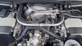
Photo attached below shows the correct wire routing.

More pictures here:
Index of /images/M119/EZL/wires


M119_ignition_wires5.jpg
 
Last edited by a moderator:
I ordered a set of these wires, they are Beru ZEF-635. Appear to be parts made in Germany, assembled in France. I measured all the wire lengths and they are just about perfect, ±1 inch, better than most aftermarket sets. Photos attached below. These are FAR better quality than the Bosch wire sets with gray wire and orange plastic plug boots, for roughly the same price.

Note that PartsGeek charges sales tax for the state you live in (they don't show this until the final page of checkout). They have a coupon for $15 off an order over $300, code SAVE15, in case you find anything else on their site you might need.

Trae, thanks for posting the details above!

:deniro:

Beru_ZEF635_1.jpg Beru_ZEF635_2.jpg Beru_ZEF635_3.jpg Beru_ZEF635_4.jpg Beru_ZEF635_5.jpg Beru_ZEF635_6.jpg
 
Experienced, exactly, the same symptoms with the 92' Renntech as the 93' 500E.

After replacing the caps, rotors, and insulators. . . still had the same symptoms.

SO. . . I replaced all wires. This time only took an hour and a half.

We will see if it takes care of the problem tomorrow.
 
Sitting around wondering whether I fixed the problem would not let me sleep tonight, so, at the encouragement of the wife, took it for a drive.

Yeeehaww!!! not a miss anywhere in 15 miles of very spirited Redline driving.

Conclusion: I probably had a bad [orange plastic] suppressor at the end of one of the old Bosch 180 degree wires.

New Berus performed flawlessly.
 
Last edited:
While I have a spare set of new Beru Wires, checking the resistance end to end before buying new is probably the best wallet friendly four letter word you can utter: T-E-S-T. :rugby: :grouphug:
 
Since this is my second go at this, I am going to post a "how to" here using GSXR's pictures. Moderators can edit or move to wherever would be helpful to the group. The first time took 4 hours, the second only 1 hour and 30 minutes.

Tools:
5mm hex
Wurth Rubber Care, or another silicone lubricant.
Stubby Phillips head screw driver

Wires: W0133-1599712 | Partsgeek.com

1. Lay out your new wires on table from shortest to longest. Use GSXR's chart to determine.
Note that the Beru wires are 1-2" longer than the chart for each cylinder.


Only had a yard stick, so, I converted to inches.

2. Since the Beru wires are 1-2" longer, I started with the shortest and labeled each wire with wire markers thusly. Remember that NONE of the wires will be exact. All will measure 1-2 in. longer.

So, from shortest to longest, per EPC data:

Cylinder 6- 790mm, or 31.1024in.​
Cylinder 2- 850mm, or 33.464in.​
Cylinder 4- 885mm or 34.84in.​
Cylinder 5- 900mm or 35.43in.​
Cylinder 1- 955mm or 37.59in.​
Cylinder 3- 990mm or 38.97in.​
Cylinder 7- 990mm or 38.97in.​
Cylinder 8- 1015mm or 39.96in.​

GSXR EDIT: The EPC data is not ideal, and does not match the aftermarket wire lengths. The chart below will work for the Beru ZEF-635 aftermarket wire set. Lengths shown are from center of boot to center of boot, which is slightly longer than measuring the exposed wire (boot collar to boot collar).

1 = 38.5'"
2 = 34.5"
3 = 40"
4 = 38"
5 = 36.5"
6 = 32"
7 = 40"
8 = 41"
Coil 1 = 24"
Coil 2 = 44.5"


Clip on markers:


These wire markers will expand with heat and slip around on the wire after installation. You may want to find other markers that won't slip, like these:


3. Remove air box and cover MAF intake with rag to prevent dirt/dust from entering.
4. Remove the metal bracket at the back of the passenger plastic spark plug covering with 5mm hex. Remove four large plastic screws with Phillips head screwdriver from top of valve covers.
5. Remove plastic coverings from cap and rotors.
6. Remove spark plug wires by pulling straight up at spark plugs and remove from caps on both sides.
7. Remove wires. I found that there is just enough room to slip the wire part of the wire out, one at a time, between the front valve covers and the fuel rail. Also remove both coil wires noting their routing.

This is where your Wurth Rubber Care, or silicone lubricant will make it easy.

Install wires. GSXR' pictures are worth a thousand words here.


This photo shows the correct wire routing:
http://www.w124performance.com/images/M119/EZL/wires/M119_ignition_wires5.jpg

More pictures here:
Index of /images/M119/EZL/wires

The routing wire numbers are very small and stamped on the plastic tracks. I took a picture and blew it up so I could see the numbers.

8.Lay the shortest coil wire first, then the longest coil wire in the deepest front track.

Since the wires are all 1-2in. too long, I started from the cap and routed in the tracks to the valve cover. Doing it this way provided enough room to install the plastic covering cap and rotors. Again, Rubber Care/silicone spray made it easy to slide in the tracks.
You can manipulate the wires under the spark plug cover to take up any slack to make your installation look like GSXR's pictures.

9. Route cylinders 1 and 4 wires first. Note that they lay in the tracks side by side, and make a u-turn in the plastic trays to passenger side cap.
10. Route cylinders 5 and 8 next. They also lay in tracks side by side and make a u-turn in the plastic trays to drivers side cap.
11. Route cylinders 6 and 7 next. Note the route in the pictures from driver's side to passenger side as the two wires make a slight S turn in the middle.
12. Route cylinders 3 and 4 next. Again, refer to GSXR's pictures for routing.

Try to make your installation look like GSXR's pictures. Then the black plastic cap and rotor covers will finally fit as they should.
However, you may want keep them uncovered to show off because they are BABE magnets!!!


M119_ignition_wires5.jpg

 
Last edited:
Just as a heads up, I bought and installed Kingsborne wires on the weekend. They have BREMI ends (plugs in to the distributor cap) and BERU boots (connects to the spark plugs). The wires are labelled. #1 is way to long and #4 is way to short . So I exchanged them and relabeled.
Silicon grease really helps the job go smoothly. The only issue I ran into is by the Power steering reservoir as I could not get under it, but made it work. Anyone have a similar issue?
 

Attachments

  • 20210515_210616.jpg
    20210515_210616.jpg
    3 MB · Views: 32
  • 20210515_210625.jpg
    20210515_210625.jpg
    1.2 MB · Views: 32
A lot of the aftermarket wire sets have non-optimal, if not totally incorrect, lengths. That is why the Beru set is so nice, it has near-perfect lengths. However they are not numbered, you need to figure out which is which. See the chart in post #8 above, for the Beru wires, to determine which goes where.

Routing everything is not easy. As Trae noted above, for the X-shaped plastic tray, the routing wire numbers are very small and stamped on the bottom of the plastic tracks. Follow these, and Trae's instructions, and the wires should lay neatly everywhere. Slight adjustments may be needed at either end to make them perfect. This may require taking wires out to adjust ones underneath. Takes a couple hours to do it well enough that @Jlaa would approve.

:jono:
 
Since this is my second go at this, I am going to post a "how to" here using GSXR's pictures. Moderators can edit or move to wherever would be helpful to the group. The first time took 4 hours, the second only 1 hour and 30 minutes.

Tools:
5mm hex
Wurth Rubber Care, or another silicone lubricant.
Stubby Phillips head screw driver

Wires: W0133-1599712 | Partsgeek.com

1. Lay out your new wires on table from shortest to longest. Use GSXR's chart to determine.
Note that the Beru wires are 1-2" longer than the chart for each cylinder.


Only had a yard stick, so, I converted to inches.

2. Since the Beru wires are 1-2" longer, I started with the shortest and labeled each wire with wire markers thusly. Remember that NONE of the wires will be exact. All will measure 1-2 in. longer.

So, from shortest to longest, per EPC data:

Cylinder 6- 790mm, or 31.1024in.​
Cylinder 2- 850mm, or 33.464in.​
Cylinder 4- 885mm or 34.84in.​
Cylinder 5- 900mm or 35.43in.​
Cylinder 1- 955mm or 37.59in.​
Cylinder 3- 990mm or 38.97in.​
Cylinder 7- 990mm or 38.97in.​
Cylinder 8- 1015mm or 39.96in.​

GSXR EDIT: The EPC data is not ideal, and does not match the aftermarket wire lengths. The chart below will work for the Beru ZEF-635 aftermarket wire set. Lengths shown are from center of boot to center of boot, which is slightly longer than measuring the exposed wire (boot collar to boot collar).

1 = 38.5'"
2 = 34.5"
3 = 40"
4 = 38"
5 = 36.5"
6 = 32"
7 = 40"
8 = 41"
Coil 1 = 24"
Coil 2 = 44.5"


Clip on markers:


These wire markers will expand with heat and slip around on the wire after installation. You may want to find other markers that won't slip, like these:


3. Remove air box and cover MAF intake with rag to prevent dirt/dust from entering.
4. Remove the metal bracket at the back of the passenger plastic spark plug covering with 5mm hex. Remove four large plastic screws with Phillips head screwdriver from top of valve covers.
5. Remove plastic coverings from cap and rotors.
6. Remove spark plug wires by pulling straight up at spark plugs and remove from caps on both sides.
7. Remove wires. I found that there is just enough room to slip the wire part of the wire out, one at a time, between the front valve covers and the fuel rail. Also remove both coil wires noting their routing.

This is where your Wurth Rubber Care, or silicone lubricant will make it easy.

Install wires. GSXR' pictures are worth a thousand words here.


This photo shows the correct wire routing:
http://www.w124performance.com/images/M119/EZL/wires/M119_ignition_wires5.jpg

More pictures here:
Index of /images/M119/EZL/wires

The routing wire numbers are very small and stamped on the plastic tracks. I took a picture and blew it up so I could see the numbers.

8.Lay the shortest coil wire first, then the longest coil wire in the deepest front track.

Since the wires are all 1-2in. too long, I started from the cap and routed in the tracks to the valve cover. Doing it this way provided enough room to install the plastic covering cap and rotors. Again, Rubber Care/silicone spray made it easy to slide in the tracks.
You can manipulate the wires under the spark plug cover to take up any slack to make your installation look like GSXR's pictures.

9. Route cylinders 1 and 4 wires first. Note that they lay in the tracks side by side, and make a u-turn in the plastic trays to passenger side cap.
10. Route cylinders 5 and 8 next. They also lay in tracks side by side and make a u-turn in the plastic trays to drivers side cap.
11. Route cylinders 6 and 7 next. Note the route in the pictures from driver's side to passenger side as the two wires make a slight S turn in the middle.
12. Route cylinders 3 and 4 next. Again, refer to GSXR's pictures for routing.

Try to make your installation look like GSXR's pictures. Then the black plastic cap and rotor covers will finally fit as they should.
However, you may want keep them uncovered to show off because they are BABE magnets!!!


View attachment 114649


Which ones are these red wires @gsxr ? These? W0133-1599712 | Partsgeek.com
 
Sad news, nothing lasts forever. At this time the Beru plug wires are $300.99 on their website. :runexe:

Good news is that partsgeek still shows the wires priced at $215.97 a set.:thumbsup2:
 

Attachments

  • 1751896656692.png
    1751896656692.png
    211.8 KB · Views: 6
Last edited:
Back
Top