• Hi Guest !

    Welcome to the 500Eboard forum.

    Since its founding in late 2008, 500Eboard has become the leading resource on the Internet for all things related to the Mercedes-Benz 500E and E500. In recent years, we have also expanded to include the 400E and E420 models, which are directly related to the 500E/E500.

    We invite you to browse and take advantage of the information and resources here on the site. If you find helpful information, please register for full membership, and you'll find even more resources available. Feel free to ask questions, and make liberal use of the "Search" function to find answers.

    We hope you will become an active contributor to the community!

    Sincerely,
    500Eboard Management

HOW-TO: Replacing 500E/E500 A/C Compressor

gerryvz

Site Honcho
Staff member
This HOW-TO is focused on replacing the A/C compressor in the V-8-based W124 Mercedes-Benz models. Since the compressor and key components of the A/C system are very similar on other W124 models, most of this HOW-TO should also apply to the inline-six models.

The Nippon Denso compressor as used in the W124 MB models is generally very reliable. However, "accessory" items such as the electromagnetic clutch on the front of the compressor, and the RPM sensor on the rear, do tend to go out with age, mileage and usage. The clutch is considered a "wear" item, and with use will wear down and eventually have difficulty engaging when the signal is sent by the climate control system to do so. Often this will show up as codes from the BM (Base Module) computer that indicate clutch non-engagement and/or belt slippage. RPM sensor failure or intermittent engagement can also show a "belt slippage" code, because the engine's RPM is being sensed by the BM as not being in sync with the compressor RPM due to failure of the sensor.

Both the RPM sensor and the clutch can be removed from the compressor and replaced; however, only the clutch assembly is available from MB as a separate component. The price on the clutch is somewhere around $150; you can purchase a brand-new Denso compressor via Amazon or other online sources for not much over $200, and via many other sources for $250-275, which is a more typical price. If you want to replace the RPM sensor, you would have to find a used one from another compressor; it is (again) just easier to remove and replace the entire compressor, which has NEW clutch and RPM sensor attached.

Note that if you wanted to remove the clutch or RPM sensor to replace them, it is pretty much de rigeur to remove the compressor to do so, so that you have everything exposed on the workbench. And again, since you would have to remove the compressor, doing all the work, it's just easier to remove and replace the entire compressor assembly and get new components with it.

R&R of the compressor assembly is roughly about a Level 5 job, on a 1-10 difficulty scale.

Tools reqiured:
  • Pair of ramps and/or lift
  • Pair of wheel chocks, if using ramps
  • 8mm socket and appropriate 1/4" ratchet (an extension is optional)
  • 3/8" ratchet
  • E10 "female" (internal) Torx socket (for belt tensioner on later E500E models)
  • Set of A/C gauges
  • R-134a refrigerant can tap
  • A/C vacuum pump
  • Set of A/C o-rings
  • 13mm wrench
  • 13mm offset box-end wrench (if available)
  • 8mm, 10mm and 13mm sockets (1/4" and 3/8" ratchets)
  • 5mm Allen key
  • 6mm Allen key or Allen socket
  • short and long 3/8" socket extensions
  • Two measuring cups (from kitchen)
  • more
  • more

Fluids required:
  • 8 oz of PAG-46 refrigerant oil
  • Three 12-oz cans of R-134a refrigerant
Prerequisite job:
It is important, before you open the A/C system or remove any components, that you properly evacuate the A/C system of refrigerant. This is best done by a professional shop that has an R134a refrigerant evacuation machine. Have the shop evacuate the system with their machine, and in the process they can pull a vacuum on the system. Pulling a vacuum will tell you whether you have any leaks in the system (before you get started), which is helpful information to know. Generally it takes about 45-60 minutes for a shop to evacuate the system, and would generally cost $75-125 to have them do this. This is more responsible than just venting the refrigerant into the atmosphere, which in the past has been illegal.

Getting to the job:
The first step, after evacuating all refrigerant from the A/C system, is to get the car positioned properly. You will need to pull the car up on ramps, or put it on a lift if you have one. Ramps (or jack stands) are just fine; they should provide plenty of clearance under the car, and the compressor is located on the bottom side of the engine on the driver's side. So, it is relatively easy to access for this job.

In this case, I used ramps for the job. Pull the car up on the ramps, apply the parking brake, and secure one of the back wheels with a pair of wheel chocks. This will keep it stable and secure for the work you are going to do.
IMG_1509.JPG IMG_1511.JPG


The next step is to open the hood. Put it in the vertical position for best access to everything, if you have the overhead space to raise it.
IMG_1512.JPG IMG_1513.JPG


After that, get underneath the car, and use your 8mm socket and ratchet/extension to remove the eight screws that hold the plastic underbelly panel to the bottom of the engine compartment. Note that my panel, after driving the car nearly 2,500 miles after last year's Top End Refresh, has ZERO oil drops or other oily gunk on the belly pan..just a little bit of dirt/dust that blew in, but this is of no concern. This made me very happy to see!
IMG_1506.JPG IMG_1507.JPG


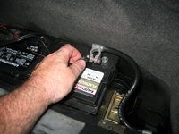
The next step is to disconnect the battery. Loosen and remove the negative battery terminal from the battery, using your 13mm box-end wrench. I wrap the negative terminal in a dry rag, and set it aside next to the battery so that it doesn't make contact with anything.
IMG_1518.JPG IMG_1519.JPG IMG_1520.JPG


Next up, remove the driver's side "zoom tube" from the intake air-box and the headlight airflow scoop.
IMG_1514.JPG


Unplug the intake air temperature sensor from the headlight airflow scoop and set it aside. Then pull up on the scoop to remove it from the car.
IMG_1515.JPG IMG_1516.JPG IMG_1517.JPG


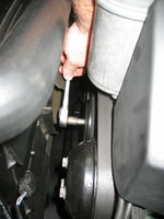
Next up, loosen the belt tensioner to free the belt. Later E500E owners with the revised belt tensioner design have it somewhat easier here. If you have the later tensioner design, you'll need your E-10 female/internal Torx socket to do this properly.

Rotate the belt tensioner toward the passenger side of the engine compartment to loosen the slack on the belt. This should free up enough slack so that you can slip the belt off of the tandem pump pulley, and other pulleys in the engine compartment as shown. Slip the serpentine belt off of the A/C compressor pulley, located underneath the tandem pump pulley. You should be able to do this from above with no problem.
IMG_1521.JPG IMG_1522.JPG IMG_1523.JPG


More to come as the job progresses. This post will be updated with additional tools and other equipment on an ongoing basis.
 
Last edited:
FYI - the refrigerant evacuation machine does not remove all oil from the system. There will still be oil spread throughout the system, and there is no way to measure how much. But you would absolutely not want to put 8oz in. PAG oil is typically sold in 250mL/8oz containers, but you won't use all of it.

The FSM specs for oil capacity are, IMO, extremely confusing and unclear (click here). But they imply the compressor may have 160cc total which is only 5.5 ounces, and the rest of the system may contain another 60-80cc (2.0-2.7 ounces). You'll want to start by measuring the amount of oil drained from the old compressor and then determine if additional amounts should be added to the new compressor (after also draining the new compressor).

:rugby:
 
FYI - the refrigerant evacuation machine does not remove all oil from the system. There will still be oil spread throughout the system, and there is no way to measure how much. But you would absolutely not want to put 8oz in. PAG oil is typically sold in 250mL/8oz containers, but you won't use all of it.
Correct. And why I mentioned only refrigerant being evacuated from the system, not refrigerant + PAG oil. Which is the environmentally sensitive element, and the responsible thing to take care of.

Screen Shot 2021-07-13 at 10.24.38 AM.jpg


The FSM specs for oil capacity are, IMO, extremely confusing and unclear (click here). But they imply the compressor may have 160cc total which is only 5.5 ounces, and the rest of the system may contain another 60-80cc (2.0-2.7 ounces). You'll want to start by measuring the amount of oil drained from the old compressor and then determine if additional amounts should be added to the new compressor (after also draining the new compressor).

:rugby:

A little bit ahead of the process, as I have not yet removed the front sway bar and motor mount cooling pipe + side encapsulation panel, nor removed the compressor yet. But I will get to all of this, and discuss it, in due time.
 
Picked up the next steps on the job today, as I had a company day-off today. Taking my time and a lot of photos, I spent about two hours out in the shop, total. Here's how the job progressed.

The first task was to remove the front sway-bar from the bottom of the car. This step is IMPERATIVE for removing the compressor, to make enough room to drop it down. It turned out not to be a big deal at all.

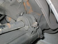
I started with the driver's side outside sway bar mount, which has two nuts that hold it to the front lower control arm. These require a 13mm socket to remove, and are not too tight. It is advisable, if you have one, to use a six-point 3/8" socket to give yourself a good bite, and enough leverage, to loosen the nuts. I loosened them in stages, and then the mount cap popped right off.
IMG_1524.JPG IMG_1525.JPG IMG_1526.JPG IMG_1527.JPG IMG_1528.JPG


Then, I turned my attention to the passenger side outside mount, and did the same thing.

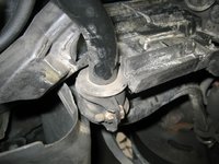
Next, I turned my attention to the driver's side inside mount. This is held by two 13mm nut-and-bolt combos, again with a cap on one side. I used a 13mm offset box-end wrench, which is ESPECIALLY helpful for the top-most nut, to get a grip on it from below, particularly because the side engine compartment encapsulation panel is right against it.

Removing the two 13mm nut and bolts for the inside sway bar mount.
IMG_1529.JPG IMG_1530.JPG IMG_1531.JPG


After doing the same operation on the passenger side inside sway bar mount, I carefully lowered the bar onto the floor.
IMG_1532.JPG IMG_1533.JPG


Here is the front sway bar, removed from the car, with the rubber mounts attached.
IMG_1534.JPG


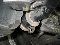
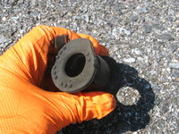
Close-up photos of the sway bar mounts. They weren't in HORRIBLE condition, but at 26 years old, and being chassis rubber, they were very due for replacement. I may have had one replaced in the past, when I lived in Portland. I'll have to look at my records to confirm that.

The next task was the remove the driver's side motor mount cooling pipe, and the side encapsulation vertical rubber panel. The cooling pipe is held on by a single plastic nut, and you can wiggle it apart from the extension/scoop assembly right behind the front spoiler. The second photo shows the cooling pipe coming down and out from underneath the car.
IMG_1537.JPG IMG_1538.JPG IMG_1539.JPG


Next was the side encapsulation panel. It is held by four screws -- three of them being 8mm, and one a 10mm screw. They screw into the frame rail and under the car. Last year, when I was doing my Top-End Refresh, I found that one of the frame rail 8mm screws was stripped, and I could not turn it out to completely remove the panel. So for this operation, I removed the three screws that I could, and then swiveled the panel downward toward the floor on the screw that I could not remove. This worked.
IMG_1540.JPG IMG_1541.JPG


The next job is to remove the three clamps that hold the power steering line (which goes from the tandem pump to the steering box) from their anchorage to the side of the oilpan and the front triangle bracket. These were very easy to do, and only require a 5mm Allen key to loosen and remove. I just pushed the bolts back into the clamps, which held them just fine. These were clean and most of the clamps were new from last year's Top-End Refresh.
IMG_1542.JPG IMG_1543.JPG IMG_1544.JPG


With the clamps removed, this allows the power steering line to be moved aside, which will be very important when dropping the compressor from its bracket.

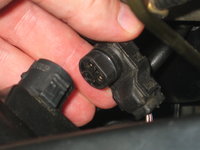
Next step was to remove the three-pin electrical connector from the top of the compressor. With the sway bar removed and the PS line able to move to the side, it was relatively easy to reach up and unfasten the connector.
IMG_1545.JPG IMG_1546.JPG


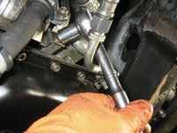
Next up, I began loosening the two 13mm long bolts that hold the compressor to the bracket. The bottom two bolts are easy to get to, and they also have a bracket that serves as the anchor point for one of the PS line clamps.
IMG_1547.JPG IMG_1548.JPG IMG_1549.JPG


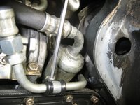
From there, I reached up and loosened the metal flange that connects the two lines to the A/C compressor. This is held on by a single 6mm Allen bolt, and was fairly easy to access. I didn't remove it all the way, preferring to this at a slightly later time.
IMG_1550.JPG


Taking a bit of a break from underneath the car, I removed the four rubber sway bar mounts from the sway bar. They pretty much slid right off the bar, with little difficulty.
IMG_1535.JPG IMG_1536.JPG IMG_1551.JPG IMG_1552.JPG IMG_1553.JPG IMG_1554.JPG IMG_1555.JPG IMG_1556.JPG


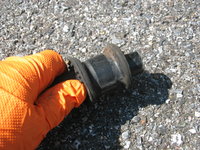
Here are the mounts immediately after removal from the bar. A little ragged, but could be worse.
IMG_1557.JPG IMG_1558.JPG


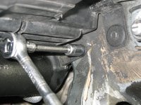
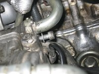
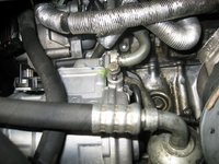
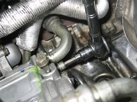
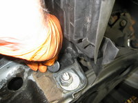
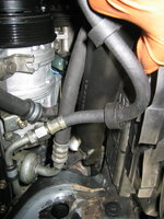
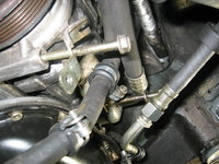
The last item to get was a single, 13mm nut that is very difficult to see. This nut is directly above the A/C hose and holds the hose to the engine. You have to reach it by feel, and then put a socket on it. In the photo below, I used a short extension and the 13mm socket, and placed it on the nut. Then I attached the 3/8" ratchet, and loosened and removed the nut.
IMG_1559.JPG


After that, I then further loosened and then removed the 6mm Allen bolt that attaches the A/C line flange to the compressor. You can see it while I was loosening it, and then removed.
IMG_1560.JPG IMG_1561.JPG IMG_1562.JPG


The next step was to remove the two remaining long bolts that held the compressor to its bracket. You have to be careful as the compressor weighs about 12 pounds, so you need to hold it, especially when loosening and removing the last bolt. For the top-most bolt that is closest to the pulley, I used a foot-long 3/8" socket extension to give me enough room to get a purchase on the bolt. This worked fine.
IMG_1563.JPG


The compressor then drops down in a forward direction, at an angle. Be careful not to tip it so as not to let any PAG oil in the compressor leak. Keep the manifold (hose attachment to the compressor) in a vertical/upright position as it is mounted to the car, when lowering the compressor.

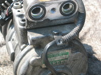
Here are some views of the compressor, as removed from the car.
IMG_1564.JPG IMG_1565.JPG IMG_1566.JPG IMG_1567.JPG


A close-up of the manifold on the top of the compressor. The hole in the center is where the 6mm Allen bolt goes in.
IMG_1568.JPG


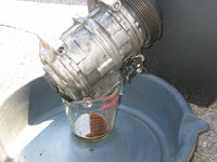
From there, I removed the manifold for better drainage access, and turned the compressor upside down to drain the PAG oil from it. When draining it, you can gently turn the clutch about 20 times to ensure that the oil moves and then drains out. Let it drain for about 15 minutes, returning once or twice to gently turn the clutch a few times. I only got about 1.5 ounces of oil out of the compressor -- likely because some of it was removed throught the refrigerant evacuation process.
IMG_1569.JPG IMG_1571.JPG


A view of the manifold as removed from the top of the compressor.
IMG_1570.JPG


While the compressor was draining, I cleaned off the sway bar with a rag with some brake cleaner on it, and then installed the four new sway bar mounts onto the bar. The inner mounts (larger inner diameter) require a bit of lubrication to get past the curve and into position, so I used a few sprays of silicone lubricant spray to help it along. The silicone lube will pretty quickly evaporate, but it did the trick as you can see from the photos below.
IMG_1572.JPG IMG_1573.JPG IMG_1574.JPG IMG_1575.JPG IMG_1576.JPG IMG_1577.JPG


TO BE CONTINUED....
 
Last edited:
A couple of notes as I get into the job today. As noted, the old compressor only had about 1.5-1.75 ounces of PAG lubricant oil in it. This is likely because some of the oil was evacuated along with the refrigerant.

I unboxed and disassembled the manifold on the top of the new compressor. Emptying it of factory-fill fluid, it had just over four ounces of clear PAG oil in it. I drained it and am going to replace with the factory recommended fill of 5.4 ounces / 160 cubic centimeters (mandated for a new compressor) along with an half-ounce or so for the rest of the system, making a total fill of around 6 ounces of PAG-46.

The next step is to re-install and reconnect the compressor, and pull a vacuum to ensure there aren't any system leaks. I'll pick up the story later today. I'm taking my time with the job and enjoying this first REAL foray into A/C work. It, along with transmissions, is one of the last frontiers of W124/126 work that I've never really delved into.....

Cheers,
Gerry
 
Here's the next installment of the A/C compressor replacement.

Here are a few comparison photos of the old compressor and the new one. As you can see, they are nearly identical. Also interestingly, the new compressor came with a proper manifold, which meant that I didn't have to use the old compressor's manifold (where the A/C hoses connect to the compressor).
IMG_1578.JPG IMG_1579.JPG IMG_1580.JPG


Next, I examined the three-pin electrical connector. Other than being a little greasy, it appeared to be fine, although the wiring was a little heat-baked. It didn't seem quite as bad as requiring repair or replacement, but it is likely going to require this, because I am sure it is the "biodegradable" wiring.
IMG_1583.JPG


Then, I removed the manifold from the top of the new A/C compressor, and drained it of the PAG oil that it had shipped with. Turning the clutch helps drain the compressor more rapidly. I got just over 4 ounces of PAG oil out of the compressor, as you can see from the Pyrex measuring cup that I borrowed from my wife's cabinet.
IMG_1584.JPG IMG_1585.JPG


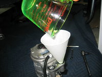
Next up, it was time to replace the clear PAG oil that the compressor shipped with, with my own PAG oil with the proper level. I decided to put almost six ounces of PAG-46 oil (with green fluorescent dye) into the compressor. It probably worked out to about 5.5 ounces with drippage and spillage, which is just about right.
IMG_1587.JPG IMG_1588.JPG


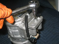
Then, I removed the shipping plate from the manifold, with the single 6mm Allen bolt that held it on.
IMG_1590.JPG IMG_1591.JPG IMG_1592.JPG IMG_1593.JPG


This exposed the open ports of the compressor. You want to fill the compressor by putting it on end (resting it on the pulley/clutch) in a vertical position. I used a paper funnel, and poured the new PAG oil into the compressor's low-side port (the larger diameter hole).
IMG_1594.JPG IMG_1595.JPG


Then, for mixing and circulation purposes, I re-attached the shipping plate, but did not tighten it. This is to cap the ports off for the next operation.
IMG_1596.JPG


What you want to do next, is put the compressor back into its normal position, and rotate the compressor clutch by hand about 8-10 times. This circulates the newly filled PAG oil in and among the compressor components, and will make sure it is properly lubricated when the compressor first starts up.
IMG_1597.JPG


By the way, here is the bolt that I mentioned, that has a 13mm nut, that holds the suction hose in place to the engine block when it is installed and in place (the hose flange is attached to the compressor's manifold. I finally was able to get a good photograph of this bolt.
IMG_1598.JPG


Now, it was time to install the compressor back into the car. I removed the shipping plate from the compressor's flange. After doing this, you MUST hold the compressor level, or with the manifold ports tipped into an upward angle, so that the PAG oil doesn't leak out.
IMG_1599.JPG


Here, I am lifting the compressor at an angle upward (with the clutch/pulley at a downward angle) and into place underneath the engine.
IMG_1600.JPG


And here, the compressor is in place. I temporarily installed the two lower bolts to hold it in place, and then installed the rear-most upper bolt as you can see in the photo.
IMG_1601.JPG


Here the compressor is finally in place, and I have begun tightening the upper-most bolt. You can see that the suction hose flange is nearly in position, as well.
IMG_1602.JPG


The compressor will be a bit loose, but the bolts that you started should hold it in place in its bracket. Finish installing finger-tight the remaining bolt(s) on the upper side. Then you can begin connecting the suction hose flange to the compressor's manifold. You want to be VERY CAREFUL that you line both ends of the suction hose pipes up with the compressor manifold, and ENSURE that the o-rings aren't pinched or otherwise compromised. Start the 6mm Allen center bolt and tighten it with your fingers.
IMG_1603.JPG

Once you have confirmed by sight (visually) and by feel (with your fingertips all around the manifold edges) that the hose flange and manifold are mated correctly, you can use your 6mm Allen socket to tighten the center flange bolt. Then, you want to torque it down to the MB specified 23Nm +/- 2.3Nm (I just torqued it to 24 Nm).
IMG_1604.JPG


Then, use your torque wrench and a 13mm socket to tighten down the four long bolts that hold the compressor to its bracket. The torque rating for these four 13mm bolts is the same -- 23Nm +/- 2.3Nm. Remove the bottom two bolts and thread them through the long metal bracket, which serves as a hold-down for a couple of the clamps for the power steering and A/C lines along the bottom of the engine.
IMG_1605.JPG


Next, connect the three-prong electrical connector to the connector on the top of the compressor.
IMG_1606.JPG


Then you can begin attaching the four clamps for the power steering, A/C and transmission cooler lines to the bracket that you just installed, and to the oilpan and the front of the engine. There should be four clamps -- three of them take 5mm Allen sockets/keys, and one takes a 10mm socket.
IMG_1608.JPG IMG_1609.JPG


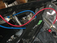
Then the real fun begins. The next step is to see whether the system is tight and doesn't have any leaks, and holds vacuum. Connect your vacuum gauge set to the low side (blue hose/connector) and the high side (red connector) by removing the caps, snapping on the connectors, and turning the connector valves in a clockwise direction to open the Schrader valves.
IMG_1610.JPG IMG_1611.JPG IMG_1612.JPG IMG_1613.JPG IMG_1614.JPG


Then, connect the yellow hose to your vacuum pump. Once you are confident that all of your connections are tight to the high and low-side ports, and to the vacuum pump, turn the vacuum pump on. Then open the high-side and low-side manifold valves (by turning them counter-clockwise ... the opposite direction of the service port connector valves. The pump should immediately begin pulling vacuum, and it should quickly settle between 29 and 30 inches of Hg (mercury) on the low-side dial gauge. The high side gauge should also go down below the Zero mark. You can see the low-side gauge below.
IMG_1617.JPG IMG_1619.JPG


Run the vacuum pump for a full five minutes. Then, shut off the MANIFOLD valves by turning them clockwise (both the high side and the low side). Turn the vacuum pump off (IMPORTANT -- it is important to close the manifold service valves BEFORE turning the vacuum pump off). Observe the exact position of the low-side gauge needle when you do this.


To be continued.......
 
My low-side vacuum gauge needle was at ~29.5 inches of Hg (mercury) when I closed the valve and then shut off the pump.

I came back to it approximately 45 minutes later and the gauge needle had not moved, indicating that the system was tight and holding vacuum. Perfect.
IMG_1622.JPG


At that point, it was time to begin pulling a total vacuum on the system. After opening up both valves at the manifold gauge, I started the vacuum pump up again, noting the time I started (12:25 PM). I then let the pump run for around 2 hours and 15 minutes, checking on things every 30 minutes or so to ensure that the pump was still running and it was pulling vacuum. The gauge stayed pegged at 29.5 inches of Hg the entire time I was running the pump.
IMG_1623.JPG IMG_1624.JPG IMG_1625.JPG


Connections to the A/C ports, and the vacuum pump running.
IMG_1626.JPG IMG_1627.JPG


After 2.25 hours, I closed off both of the valves at the manifold, and then turned off the pump. All was still well at 29.5 inches Hg.
IMG_1628.JPG


Now that the system was evacuated, it was time to fill it with fresh, new R-134a refrigerant. The system takes just under three full 12 oz cans of R-134a, so this is how much you want to have on hand.

@LWB250 gave me a hot tip to get a bucket of very hot water from the tap, to immerse and swish the cans in as they unloaded their refrigerant into the A/C system. I got a large, 5-gallon bucket and filled it about one-half full with the hottest tap water I could draw. Then I poured in a full electric kettle of boiling water to raise the temperature of the water even more.
IMG_1629.JPG


I got my first can of refrigerant, and screwed my can tap onto the top of it. Then I attached the yellow hose from the A/C gauge set. Then I turned the can tap to drive the Schrader valve in the top of the can down, to begin discharging refrigerant into the yellow line. Of course, the manifold valves were still closed.
IMG_1631.JPG IMG_1632.JPG


Acting on another tip from @LWB250, I twisted the yellow hose fitting at the manifold gauge set for about 1/2-1 second to purge the yellow line of air. This was the last step before I opened the BLUE manifold valve, to allow the refrigerant to begin to flow into the car's A/C system through the low-side (blue) line.
IMG_1633.JPG


Opening the blue valve only (DO NOT OPEN THE RED MANIFOLD VALVE) to let refrigerant begin to enter the system.
IMG_1634.JPG


After the refrigerant begins to flow, you will immediately feel the outside of the can get cold, and begin to sweat. This is the time to immerse it in the hot water in your bucket, slowly moving the can back and forth in the water, and swishing it around. This external heat against the can will hasten the passage of the refrigerant into the car's A/C system.
IMG_1635.JPG


After a couple of minutes, you will feel the refrigerant can get very light, and shaking it will show that there is no refrigerant left in the can. Turn off the blue manifold valve, and remove the can tap from the can. You will see a little "hiss" as the last remnants of the refrigerant escape when you remove the tap. You will probably see somewhere around 80-90 PSI of pressure indicated on the low-side (blue) gauge after the first can of refrigerant has been introduced, and probably somewhere around 90-100 PSI on the high (red) side gauge.

Start your second can of refrigerant, using the same process. Don't forget to purge the air from the yellow line (as mentioned above) with a quick twist of the yellow line connector, before opening the blue manifold valve again. Using the same procedure, empty the second can of refrigerant into the system.

After the second can has been introduced into the system, you will see a system pressure of around 100-105 PSI on the low (blue) side, and 110-120 PSI on the high side.

At this point, you should have enough refrigerant in the system that you will be able to trigger the compressor, and get the remaining amount of the refrigerant charge into the system. Remove and attach the third can of refrigerant per the above procedure, and purge the yellow line of air.

The next step is to re-install the serpentine belt onto the pulleys and on the new A/C compressor pulley. Use the reverse of the process by which you untensioned the tensioner and removed the belt at the beginning of the job.

Then, re-connect the battery in the trunk, and start the car. Let it run for a minute or two at idle, and warm up a bit. Activate the compressor via the push-button unit in the dash. If all of the other components are working, the compressor should immediately fire up and begin turning. Test it by switching the A/C on and off via various settings, checking the compressor status to see if the clutch is turning or not. It should work as advertised.

Take a look into the sight-glass at the receiver-drier. You will probably see alternating bubbles and clear refrigerant inside as the A/C system pressure cycles. You will also see the pressure on the gauges climbing and falling around 5-10 PSI on the low side as the compressor cycles.
IMG_1643.JPG


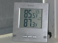
Then, using the procedure above and with the car and A/C system running on "High," administer the third can of refrigerant into the system, using the water bucket method. Check the system pressures after doing this against the external temperature. In my case, the ambient temp was around 85F, so this mandated around 40-45 PSI on the low side, and 220-225 PSI on the high side. Generally, my pressures were right on.
IMG_1644.JPG


Also, while I was loading the third can of refrigerant into the system, the low-speed fans kicked on, as appropriate.

After you determine that everything is working well, get back underneath the car and check for leaks, particularly at the manifold and suction hose flange area on the top of the compressor, and at the front seal where the compressor pulley shaft goes into the compressor body. All should be good, but it is a good thing to double-check.

If everything checks out, it's time to begin re-assembling the final parts. The re-assembly is pretty much the reverse of disassembly. First, re-install the side panel using the three 8mm and one 10mm screws that hold it to the car's frame.
IMG_1636.JPG IMG_1637.JPG


Then, re-install the driver's side motor mount cooling pipe. Fasten it into place with its plastic 10mm nut, and attach it to the end of the air-scoop behind the front spoiler.
IMG_1638.JPG IMG_1639.JPG IMG_1640.JPG


Then, re-install the front sway-bar, and then the under-belly panel, and the job is completed. Here is a photo of my engine compartment, before I re-installed the driver's side "zoom tube" and the intake air scoop behind the headlight.
IMG_1645.JPG
 
A couple of final notes for folks who do this job in the future:
  1. For the four long bolts that hold the A/C compressor to its bracket, it is highly recommended -- though it does not explicitly state in the MB work instructions -- that you use Blue Loctite on the threads of the bolts. This is to help ensure that they stay in place. The compressor is subject to a lot of vibration, and the Loctite will help keep the bolts torqued properly. Next time I have my belly pan off, I will remove the four bolts, one by one, add Loctite to the threads, and re-torque them to their 23Nm +/- 2.3Nm spec.
  2. The factory MB work instructions say that all of the front sway-bar mounting nuts should be replaced upon re-installation of the sway bar. I re-used my original nuts, but I have placed a new set of these nuts on order, and again next time I am under the car, I will replace them with fresh, new nuts. I will do the same for the four matching bolts for the inner sway bar mounts.
Cheers,
Gerry
 
Thanks for another nice, concise DIY write up as I have the same project pending. Do you have a preferred refrigerant brand/manufacturer or most conveniently available?
 
Thanks for another nice, concise DIY write up as I have the same project pending. Do you have a preferred refrigerant brand/manufacturer or most conveniently available?
If you have multiple cars, consider buying a 30-lb cylinder, which allows more precise filling of each vehicle's system. Last time I bought a tank it was ~$150 for Chemours, Made in USA refrigerant. You need a refrigerant scale to go along with the tank.

R134a_Chemours1.jpg
 
I ordered three cans of made in USA 134a off of Amazon. Easy enough.

Let us know how your job goes here on this thread. Helps when people add their experiences. I’d say this is a day’s job. I work slowly and take photos for HOW-TOs so I am very slow. Nature of the beast.
 
Adding Supplemental WIS Information
 

Attachments

  • Compressor Removal p.1.jpg
    Compressor Removal p.1.jpg
    741 KB · Views: 9
  • Compressor Removal p.2.jpg
    Compressor Removal p.2.jpg
    396.8 KB · Views: 9
  • W124 Temperature Chart.jpg
    W124 Temperature Chart.jpg
    515.9 KB · Views: 9
  • W124 AC Capacity.jpg
    W124 AC Capacity.jpg
    510 KB · Views: 9
The page with graphs, "D" in particular, is very interesting as it shows coolant temps around 100°C are normal with AC on... even with ambient temps at only 86°F/30°C:

View attachment 210342

:duck:
My off the cuff observations over many years, and with multiple cars, are that A/C operation generally adds about 5-7 degrees (F) to the indicated coolant temp on the 124 gauge. On my car, definitely +5F.
 
I always wondered if having the AC on would actually decrease the coolant temperature because the low-speed fans won't activate without the AC on. Maybe the added heat to the radiator outweighs the cooling from the low-speed fans?

EDIT: I just serviced my system using the bucket of hot water technique as described by the @gerryvz above (hat tip to @LWB250). I’ve never used this technique before. It worked very well using my (free) 5-gallon Harbor Freight bucket half full of hot tap water and an added 2 quart Pyrex of boiling water from the microwave. I also loosened the yellow supply line for a fraction of a second prior to adding every can of refrigerant as the @gerryvz suggested.
 
Last edited:
Who has viewed this thread (Total: 3) View details

Who has watched this thread (Total: 1) View details

Back
Top