Navigation
Install the app
How to install the app on iOS
Follow along with the video below to see how to install our site as a web app on your home screen.
Note: This feature may not be available in some browsers.
More options
Style variation
-
Hi Guest !
Welcome to the 500Eboard forum.
Since its founding in late 2008, 500Eboard has become the leading resource on the Internet for all things related to the Mercedes-Benz 500E and E500. In recent years, we have also expanded to include the 400E and E420 models, which are directly related to the 500E/E500.
We invite you to browse and take advantage of the information and resources here on the site. If you find helpful information, please register for full membership, and you'll find even more resources available. Feel free to ask questions, and make liberal use of the "Search" function to find answers.
We hope you will become an active contributor to the community!
Sincerely,
500Eboard Management
You are using an out of date browser. It may not display this or other websites correctly.
You should upgrade or use an alternative browser.
You should upgrade or use an alternative browser.
ASR defeat wiring diagram
- Thread starter modzona
- Start date
Re: ASR delete wiring diagram
So I got a request to make an extra "ASR delete" wiring harness.
Anyone else interested in one?
It will come complete. With the ASR off button and everything.
And enough wire to put the switch in the dash and center console. The only thing you have to do is connect the voltages and the ASR signals. + pull the wires inside the cabin of course.
Wires will be german made silicon wires that can take -60 *c and + 160*c. And high quality relays.
Every wire will have dual protection. And it will have a gasket for the hole the CAN box so no water/moisture can get inn.
Price will be 150$ +25$ in tracked/signed for shipping worldwide. This price will only available to the end of January 2016. You will have to make a 50% deposit before 1 of February.
[TABLE="class: grid, width: 500"][TR][TD]User[/TD][TD]Paid[/TD][/TR][TR][TD]Taxi Driver[/TD][TD]
[/TD][/TR][TR][TD]AMGTesTDriverNJ[/TD][TD]100%[/TD][/TR][TR][TD]500ESpain[/TD][TD]100%[/TD][/TR][TR][TD]e500.org (extra wire)[/TD][TD]50%[/TD][/TR][TR][TD]jhodg5ck x3[/TD][TD]
[/TD][/TR][TR][TD]500AMM x3[/TD][TD]100%[/TD][/TR][TR][TD]bing[/TD][TD]100%[/TD][/TR][TR][TD]peeps500 (extra wire)[/TD][TD]100%[/TD][/TR][TR][TD]Sheward
[/TD][TD]
[/TD][/TR][TR][TD]Mejnoon
[/TD][TD]
[/TD][/TR][TR][TD]lil_dz33
[/TD][TD]50%[/TD][/TR][TR][TD]hean500e (extra wire)[/TD][TD]100%[/TD][/TR][/TABLE]
Last edited:
Re: ASR delete wiring diagram

The switch/relay/wiring should work, but you will need to figure out what wires to interrupt on the M104 ASR module. I don't think I've read of anyone doing this. Steve Geyer or Russell Drake may know.Would this be compatible with a m104 w124?

Re: ASR delete wiring diagram

This is medium/advanced DIY. You have to remove all modules and partly disassemble the CAN box, then cut & splice wires in the main harness below the ASR module. Also have to remove passenger airbag, disassemble HVAC console area, route wires through the firewall, and do some more splicing inside the car. If you're not comfortable with electrical work, go slow & careful... takes me 4-5 hours but I'm picky about my electrical work.I'm interested. Could you elaborate on what exactly needs to be done to install this? Specifically, if wires need to be spliced and where. I'm weak in electrical knowledge. Thanks.

Re: ASR delete wiring diagram
 (Same here)
Eric
I'm interested. Could you elaborate on what exactly needs to be done to install this? Specifically, if wires need to be spliced and where. I'm weak in electrical knowledge. Thanks.
drew
 (Same here)
Eric
Re: ASR delete wiring diagram
As an electrician I see some faults with the way he has done it. Its not bad, just not up to my standards on wiring.
Mine will come completely sleeved and with gasket to the hole in the can box. Every connection will be crimped and soldered.
The thing you have to do your self i
- connect +/-12volts
- Put ASR top on the switch if not you can have two rear light switches up to you. If you want to mod the rear window lock switch to do this instead you can do that to. You only need a normal on/off switch in this setup.
- drill a hole in the canbox,
- pull some wires inside to the switch
- cut-connect the 6 wires with the ASR signals.
Some basic DIY skills will be needed.
Last edited:
Re: ASR delete wiring diagram
I am also interested - please PM me once you have the kits ready. Can you advise if instructions will be given to finish the install off? I will go with the ASR button in the console for ease of turning it on/off as/when - something like this would be nice.
Does anyone know if MB sells the wood console trim which has all cut-outs to add extra options? Or do the holes have to be drilled?

Re: ASR delete wiring diagram
If you can find some wiring diagrams of the ASR module on the M104 i probably find out what you need to do.
As i dont own a M104 car i cant make wiring harness to fit them.
But this harness probably will be good and just extend/cut the cabels as needed. Then its almost better to just start from scratch.
Some wood console are still in stock. This has been talked about before so just search the forum and you will find a lot about drilling new hole vs buy new wood.
Would this be compatible with a m104 w124?
If you can find some wiring diagrams of the ASR module on the M104 i probably find out what you need to do.
As i dont own a M104 car i cant make wiring harness to fit them.
But this harness probably will be good and just extend/cut the cabels as needed. Then its almost better to just start from scratch.
I am also interested - please PM me once you have the kits ready. Can you advise if instructions will be given to finish the install off? I will go with the ASR button in the console for ease of turning it on/off as/when - something like this would be nice.
Does anyone know if MB sells the wood console trim which has all cut-outs to add extra options? Or do the holes have to be drilled?
Some wood console are still in stock. This has been talked about before so just search the forum and you will find a lot about drilling new hole vs buy new wood.
Re: ASR delete wiring diagram
OK maybe I am missing something here. I was under the impression if an ASR defeat wiring / relay configuration was installed like this one would simply pull out the "Snow Chains" Button on the upper console and replace it with a modified R129 "ASR Off" switch exactly like is shown in e500.org's post above. Is that not the case???

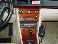
OK maybe I am missing something here. I was under the impression if an ASR defeat wiring / relay configuration was installed like this one would simply pull out the "Snow Chains" Button on the upper console and replace it with a modified R129 "ASR Off" switch exactly like is shown in e500.org's post above. Is that not the case???

Re: ASR delete wiring diagram
You can do what you want. If you feel like you dont need the "snow chains" take it away. I will not recommend it.
Correct me if i am wrong on this
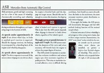
Snow chains does let you have some spin on one tire. Not maniac spin. It will also reduce power to put less stress on the drive train. And only works to 60km/h (35 ish mp/h ?)
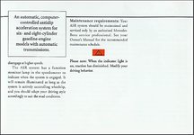
ASR delete will take the complete ASR function away. Power reduction and skid control (tyre slip). And it will not generate error codes in the ASR system. And you still will have ABS.
Personally I will only recommend taking away the snow tire switch if you have an LSD. It will do the job of make both tires spin. If you dont and take it away you are really going to be angry that one time you need it to get out of a non plowed parking space in the snow.
Edit: I am going to put the switch in the alarm led socket.
OK maybe I am missing something here. I was under the impression if an ASR defeat wiring / relay configuration was installed like this one would simply pull out the "Snow Chains" Button on the upper console and replace it with a modified R129 "ASR Off" switch exactly like is shown in e500.org's post above. Is that not the case???

You can do what you want. If you feel like you dont need the "snow chains" take it away. I will not recommend it.
Correct me if i am wrong on this
Snow chains does let you have some spin on one tire. Not maniac spin. It will also reduce power to put less stress on the drive train. And only works to 60km/h (35 ish mp/h ?)
ASR delete will take the complete ASR function away. Power reduction and skid control (tyre slip). And it will not generate error codes in the ASR system. And you still will have ABS.
Personally I will only recommend taking away the snow tire switch if you have an LSD. It will do the job of make both tires spin. If you dont and take it away you are really going to be angry that one time you need it to get out of a non plowed parking space in the snow.
Edit: I am going to put the switch in the alarm led socket.
Last edited:
Re: ASR delete wiring diagram
I have no idea how that function works. Can one of the heavy weights way in on this???
Yes that is exactly what I would want if I pursued this. Also even though my car does have a LSD I live in Southern California so snow (hell even rain) would never be an issue for me.
Thanks
Eric
Correct me if i am wrong on this
Snow chains does let you have some spin on one tire. Not maniac spin. It will also reduce power to put less stress on the drive train. And only works to 60km/h (35 ish mp/h ?)
I have no idea how that function works. Can one of the heavy weights way in on this???
...ASR delete will take the complete ASR function away. Power reduction and skid control (tyre slip). And it will not generate error codes in the ASR system. And you still will have ABS..
Yes that is exactly what I would want if I pursued this. Also even though my car does have a LSD I live in Southern California so snow (hell even rain) would never be an issue for me.
Thanks
Eric
Re: ASR delete wiring diagram
The snow chain switch can be considered as a partial or temporary ASR defeat allowing some tire spin to help one get the car moving on snow or ice as modzona states. Limited effectiveness at anything but low speeds and partial throttle. You would not need to retain it with your LS or the ASR defeat. I think some folks are just purists and understandably would like to retain it. If I go this route i'll probably just use the opening since it's reversible and cutting a new hole is a risky and exacting job. Silver Wrench award to those that have done it.
I want a Limited Slip as well. Hopefully Johnathan will still have one when my wallet's thicker.
drew
Last edited:
Re: ASR delete wiring diagram
Snow chain switch slightly changes the intervention point of ASR. Key word here is "slightly". I believe there is a chart buried somewhere in the FSM which shows the effect. There isn't much point to this switch except for the factory intended use with snow chains. I'm sure most people would never miss it if the switch was removed, or replaced with a switch of a different function.
Full ASR defeat / ASR off is very different. I've mentioned this in the past, but IMO turning ASR off is for track-only use, or hooning. I don't recommend ever turning it off for normal street driving, no matter what diff upgrades have been done to the car.

Re: ASR delete wiring diagram
Precisely...

...but IMO turning ASR off is for track-only use, or hooning...
Precisely...


Re: ASR delete wiring diagram
Led with resistor on 1 and 3 in the switch and you have light.
Will add it later.. going to do some more non critical changes on it.
Have to look in the papers. Cant remember on th spot. I will let you know.
Another stupid question... Isn't there wiring for the switch lighting?
Led with resistor on 1 and 3 in the switch and you have light.
Will add it later.. going to do some more non critical changes on it.
Thanks for the diagram and method.
Stupid question,
the blue, yellow and green wires that go out of the diagram to the top, where do they go?
cheers
Have to look in the papers. Cant remember on th spot. I will let you know.
Last edited:
Re: ASR delete wiring diagram

OK maybe I am missing something here. I was under the impression if an ASR defeat wiring / relay configuration was installed like this one would simply pull out the "Snow Chains" Button on the upper console and replace it with a modified R129 "ASR Off" switch exactly like is shown in e500.org's post above. Is that not the case???


Attachments
Re: ASR delete wiring diagram


You mean everyday driving....??Precisely...

Re: ASR delete wiring diagram
This is with shipping.
85£
115€
The prototype will be a test. Its not going to look good. It will be made just to get the wire lengths right.
Martin, how much in Euros or Sterling to UK ? Also, could you post a photo of the prototype once it's ready, please ?
Cheers
Bing
This is with shipping.
85£
115€
The prototype will be a test. Its not going to look good. It will be made just to get the wire lengths right.
Re: ASR delete wiring diagram
But, Eric I thought you were an electrician and you have the master mechanic Matt Stockwell.
(Same here)
Eric
But, Eric I thought you were an electrician and you have the master mechanic Matt Stockwell.
Re: ASR delete wiring diagram
Additional snow-chain switch info at this link, see graph on page 3:
http://www.w124performance.com/docs/mb/other/ASR_snow_chain_switch.pdf

Additional snow-chain switch info at this link, see graph on page 3:
http://www.w124performance.com/docs/mb/other/ASR_snow_chain_switch.pdf

Re: ASR delete wiring diagram
Yeah I am an electrical contractor and although I work with AC not DC the fundamental wiring concept via the relays makes perfect sense to me so that is not the problem. As for Matt I already gave him the heads up about this idea as I thought modzona's initial post and wiring diagram looked pretty well thought out and I know Matt is also interested in coming up with an ASR defeat system. In short if he is on board with this idea I am in.

But, Eric I thought you were an electrician and you have the master mechanic Matt Stockwell.
Yeah I am an electrical contractor and although I work with AC not DC the fundamental wiring concept via the relays makes perfect sense to me so that is not the problem. As for Matt I already gave him the heads up about this idea as I thought modzona's initial post and wiring diagram looked pretty well thought out and I know Matt is also interested in coming up with an ASR defeat system. In short if he is on board with this idea I am in.

Re: ASR delete wiring diagram
These wires are the specific blue, yellow and green wires from the existing socket harness connecting to the ASR CAN module. These wires get cut & then each cut end is spliced to the corresponding relay IN & relay OUT wires associated to these three circuits (throttle, braking, dash indicator light).
The most important fail-safe relay wiring consideration is to ensure that if a relay were to fail, ASR remains ON.
Thanks for the diagram and method.
Stupid question,
the blue, yellow and green wires that go out of the diagram to the top, where do they go?
These wires are the specific blue, yellow and green wires from the existing socket harness connecting to the ASR CAN module. These wires get cut & then each cut end is spliced to the corresponding relay IN & relay OUT wires associated to these three circuits (throttle, braking, dash indicator light).
The most important fail-safe relay wiring consideration is to ensure that if a relay were to fail, ASR remains ON.

Last edited:
Re: ASR delete wiring diagram
Thanks alot, understood!
These wires are the specific blue, yellow and green wires from the existing socket harness connecting to the ASR CAN module. These wires get cut & then each cut end is spliced to the corresponding relay IN & relay OUT wires associated to these three circuits (throttle, braking, dash indicator light).
The most important fail-safe relay wiring consideration is to ensure that if a relay were to fail, ASR remains ON.
Thanks alot, understood!
Re: ASR delete wiring diagram
Sorry guys but my price has to change. It will now be 150$ + 25$ in shipping.
Im really sorry for this but it will make it easier for me to make all the same. They will all have brand new"ASR off" tops on them.
It just to much of a a hazel to get a hold of them used in this amount. And i don't want ship out switches that shows signs of use in different quality.
It will also make it easier for you to fit. So that the only thing you have to do when you get it is cut and splice in to the ASR signals, fit the switch and pull one cable inside.
I will send pm to everyone that has said they are interested. And let them know and say if they are still in or not.
Re: ASR delete wiring diagram
My daily car has this so i will check that.
Hi, I'm also interested in this mod. Just have one question - will the "ASR Off" switch fit into the fader switch hole?
My daily car has this so i will check that.
Re: ASR delete wiring diagram
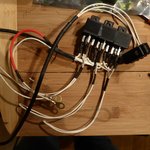
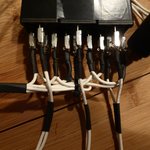
So i only had white cabel at home in the right size. And the lengths are not quite right. This is just an example of how this will be. Every cable will be in different color but ground of course. And the diagram will be the same as in the real harness.
Some stuff is not there. The switch will be separate with connectors in such way that it cant be connected wrong.
Grommet to stop water to getting in to the CAN box will be on the on the harness at the correct place.
I don't know if the relays have to go out side the CAN box or in the bottom. The rain surprised me to day when i finally got the box completely dismantled. Might get time to have a look at that tomorrow. The only different if they go outside the box is that you have to drill two holes (7.5mm) in the box. If i was only to do one, you would have to use a step drill. And thats maybe not something everybody has.


Re: ASR delete wiring diagram
Looks very nice I am glad to hear your intention to include a grommet for the penetration that is going to be needed at the CAN box. With regards to a location for the relays I was thinking space permitting trying to find a home for them in the console behind the stereo head unit and climate controls. On that note although I do not want to step on your toes what are your thoughts about sticking the relays in a small plastic enclosure? Besides it just really cleaning up the finished product if installed inside the car it would probably also help mute the sound of the relays clicking when the ASR switch was pressed. Using the connectors and the light switch in your picture as a reference for size it doesn't look like you would need something that big and there are all kinds of plastic electronics enclosures on eBay that seem like they would be perfect for an application like this.
Example: http://www.ebay.com/itm/Plastic-Ele...474?pt=LH_DefaultDomain_0&hash=item1c502b323a
Again I do not want to step on you toes but just wanted to contribute my $.02. I look forward to your continued progress on this.
Thanks
Eric

So i only had white cabel at home in the right size. And the lengths are not quite right. This is just an example of how this will be. Every cable will be in different color but ground of course. And the diagram will be the same as in the real harness.
Some stuff is not there. The switch will be separate with connectors in such way that it cant be connected wrong.
Grommet to stop water to getting in to the CAN box will be on the on the harness at the correct place.
I don't know if the relays have to go out side the CAN box or in the bottom. The rain surprised me to day when i finally got the box completely dismantled. Might get time to have a look at that tomorrow. The only different if they go outside the box is that you have to drill two holes (7.5mm) in the box. If i was only to do one, you would have to use a step drill. And thats maybe not something everybody has.
Looks very nice I am glad to hear your intention to include a grommet for the penetration that is going to be needed at the CAN box. With regards to a location for the relays I was thinking space permitting trying to find a home for them in the console behind the stereo head unit and climate controls. On that note although I do not want to step on your toes what are your thoughts about sticking the relays in a small plastic enclosure? Besides it just really cleaning up the finished product if installed inside the car it would probably also help mute the sound of the relays clicking when the ASR switch was pressed. Using the connectors and the light switch in your picture as a reference for size it doesn't look like you would need something that big and there are all kinds of plastic electronics enclosures on eBay that seem like they would be perfect for an application like this.
Example: http://www.ebay.com/itm/Plastic-Ele...474?pt=LH_DefaultDomain_0&hash=item1c502b323a
Again I do not want to step on you toes but just wanted to contribute my $.02. I look forward to your continued progress on this.
Thanks
Eric

Re: ASR delete wiring diagram
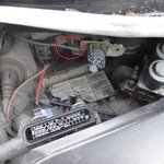
Thx! i am always open for new input. I want to have the relays originally in the CAN box. But it will be to tight it looked like yesterday when i had it open. But i did not have the test harness ready then. To have a proper fit and check.
I also dont want to take the ASR signals to far from the canbox. And as a result of that it will be less mass (cables) to pull through the torpedo wall. These types of relays have no problem being in the open to the elements. So boxing them in has no point and it will make more bulky and more hard to place.
I think the best place and easiest place will be here. Just use a zip tie or two. Then the wires from the CAN dont have to go to long. And if the relays fail some time in the future its just to cut the zip tie and pull them out to where you can work on them.

Last edited:
Re: ASR delete wiring diagram
So guys im ready to start ordering parts. So we can do this two ways. A 50% deposit or the total sum. If we do the 50% i can order everything but the "ASR off" switches. And order them when i have the harness ready for them as you pay the rest. What will make it take about 2-3weeks longer if not more.
What do you guys want?
Re: ASR delete wiring diagram
Me too
I'm ok with full payment with ASR switch .
Me too
Similar threads
- Replies
- 9
- Views
- 994
- Replies
- 2
- Views
- 675
- Replies
- 0
- Views
- 429
- Replies
- 15
- Views
- 520


