• Hi Guest !

    Welcome to the 500Eboard forum.

    Since its founding in late 2008, 500Eboard has become the leading resource on the Internet for all things related to the Mercedes-Benz 500E and E500. In recent years, we have also expanded to include the 400E and E420 models, which are directly related to the 500E/E500.

    We invite you to browse and take advantage of the information and resources here on the site. If you find helpful information, please register for full membership, and you'll find even more resources available. Feel free to ask questions, and make liberal use of the "Search" function to find answers.

    We hope you will become an active contributor to the community!

    Sincerely,
    500Eboard Management

Center Console Bulb

Do you guys guess this bright blue thick cable that goes up the steering column is factory or aftermarket?
That is factory. Note the red connector, indicating it is part of the SRS (airbag) system. It goes to the slip-ring brushes/contacts at the steering wheel.


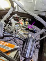
Could you please confirm if this is X6? (It's located 2-4 inches behind the ashtray)

View attachment 131661
@kiev, I think you have have solved the Mystery of the Missing X6!

:love:

1622414092579.png


Found it. The siren was actually by windshield washer fluid container and a "brain" (?) Seco-larm ss-057 was neatly tucked close to driver height. Cut their respective cables and pulled them into the driver's foot well. Now all of this tragedy is out:
View attachment 131664
:wahoo:
 
TEST 1

what happens if you touch the positive of a 9v battery to pin2 of N40 relay (58D) and the negative terminal of the 9v battery DIRECTLY to the negative terminal of ONE window switch illumination….

You may have to fashion a jumper wire of some sort but the positive terminal of the window switch should be connected to the car and the negative terminal of the window switch should NOT be connected to the car.

TEST 2

Also what if we do the reverse? Positive term of 9v battery DIRECTLY to positive illumination terminal of ONE window switch bulb and negative term of 9v battery to some chassis ground like w12 or w1?

You may have to fashion a jumper wire of some sort but the NEGATIVE terminal of the window switch should be connected to the car and the POSITIVE terminal of the window switch should NOT be connected to the car.
Jlaa, for test #1:

  1. 9 volt battery positive terminal into N40 connector (pin 2, 58D)
  2. Window switch is NOT plugged into its connector - 9 volt battery negative terminal to negative pin of the window switch
  3. Window switch is NOT plugged into its connector - find a wire and connect its one end to positive pin of the window switch and the other end into a respective pin of the window connector
All other window switch pins remain unplugged? Did I get this correct?


:update:

Confusion abounds. Now that - apparently - I did tests correctly, using a total of 3 wires: 9V batter positive, 9V batter negative, AND a 3rd wire from window switch connector TO window switch pin - both tests, as in BOTH #1 AND #2, light up an individual window switch....

I also remeasured a resistance between pin 2 (58D) of N40 connector and W12 ground - and got zero ohm. Same between pin 2 (58D) and front ceiling light ground - zero ohm

🤯
 
Last edited:
Jlaa, for test #1:

  1. 9 volt battery positive terminal into N40 connector (pin 2, 58D)
  2. Window switch is NOT plugged into its connector - 9 volt battery negative terminal to negative pin of the window switch
  3. Window switch is NOT plugged into its connector - find a wire and connect its one end to positive pin of the window switch and the other end into a respective pin of the window connector
All other window switch pins remain unplugged? Did I get this correct?


:update:

Confusion abounds. Now that - apparently - I did tests correctly, using a total of 3 wires: 9V batter positive, 9V batter negative, AND a 3rd wire from window switch connector TO window switch pin - both tests, as in BOTH #1 AND #2, light up an individual window switch....

I also remeasured a resistance between pin 2 (58D) of N40 connector and W12 ground - and got zero ohm. Same between pin 2 (58D) and front ceiling light ground - zero ohm

🤯
Well! this is progress! Through tests 1 and 2, you have established that pin2 (58D) of the N40 socket IS CONNECTED to the window switch positive illumination connector! You have also established that w12 chassis ground IS CONNECTED to the window switch neg illum connector! Good progress.

Because you measure 0 ohms between n40 pin2 58D socket and chassis ground w12, I am reasonably sure that the reason why some of your illumination is not working is because you n40r pin2 58D socket is somehow shorted to chassis ground. You can confirm this by re running test 1 and using the mutimeter to measure voltage between w12 chassis ground and the negative terminal of the battery. I bet this will show 9 volts, which definitely would confirm n40 pin2 58D socket is shorted to chassis ground!! You just need to figure out why. 🥺. I would also no be surprised if all three of your n40s are now unfortunately fried (bc of the short to ground condition)

BTW is the instrument cluster connected?
 
Could you please confirm if this is X6? (It's located 2-4 inches behind the ashtray)
Kiev, I'm pretty dang sure that is X6. When touching the red probe of your DMM to this terminal block and the black probe to chassis ground, are you seeing 12V with the headlights on?

Looking at the spaghetti pile of wires, I noticed that one wire seems to be a factory blue/grey wire the alarm "installer" spliced into. It looks like it runs to the blue wire of the aftermarket alarm harness, which is a negative door trigger wire (ground when door is open). This isn't correct for any alarm install, but we should see where on the vehicle it was cut.
 

Attachments

  • [500Eboard] PXL_20210530_222024686.jpeg
    [500Eboard] PXL_20210530_222024686.jpeg
    1.6 MB · Views: 7
You can confirm this by re running test 1 and using the mutimeter to measure voltage between w12 chassis ground and the negative terminal of the battery. I bet this will show 9 volts, which definitely would confirm n40 pin2 58D socket is shorted to chassis ground!!
Will try this today!

Because you measure 0 ohms between n40 pin2 58D socket and chassis ground w12, I am reasonably sure that the reason why some of your illumination is not working is because you n40r pin2 58D socket is somehow shorted to chassis ground.
Could you please explain. My understanding is that ALL of the switches that currently don't light up make up 1 circle. If the bare blue/grey wire touches bare brown wire ANYWHERE, nothing on the circuit will work. It could be inside the rear door, somewhere in a wire "highway" under the carpeting, inside a junction of several sheathes of wires joining together.... ANYWHERE, right?

If I will short pin 4 (58d) to pin 2 (58D) and then turn on lights, will I see all of the switches briefly light up, until fuse 9 burns out?

I would also no be surprised if all three of your n40s are now unfortunately fried (bc of the short to ground condition)
How long would it take for N40 to burn, like right away (a few seconds) right? All 3 were already connected several times over. 2 of them are out and I can open them up. I'll do that to take a look at the signs of burning

BTW is the instrument cluster connected?
For both testes instrument clusters main thick harness was disconnected. Car battery too, obviously.

It looks like it runs to the blue wire of the aftermarket alarm harness, which is a negative door trigger wire (ground when door is open).
Speedy, would you be kind enough to explain the bolded part in housewife's terms? Thanks
 
Because you measure 0 ohms between n40 pin2 58D socket and chassis ground w12, I am reasonably sure that the reason why some of your illumination is not working is because you n40r pin2 58D socket is somehow shorted to chassis ground. You can confirm this by re running test 1 and using the mutimeter to measure voltage between w12 chassis ground and the negative terminal of the battery. I bet this will show 9 volts, which definitely would confirm n40 pin2 58D socket is shorted to chassis ground!!
In-mucking-deed it shows 9 volts... @jlla, mate, without you chewing things out for me I wouldn't have gotten anywhere.

So blue/grey and ground wires paths are uninterrupted and intact, but somewhere.... SOMEWHERE in the circuit bare blue/grey and bare ground wires come in contact 🔍🔍🔍
 
Last edited:
@Jlaa, another question. The W12 ground point (red arrow) has x2 ground cables connected to it (circled in blue). If I disconnect both of them and perform test #2 (connect negative terminal of the 9 volt battery to W12) an individual window switch still lights up... Does that mean anything?


5th1.jpg
 
Last edited:
In-mucking-deed it shows 9 volts... @jlla, mate, without you chewing things out for me I wouldn't have gotten anywhere.

So blue/grey and ground wires paths are uninterrupted and intact, but somewhere.... SOMEWHERE in the circuit bare blue/grey and bare ground wires come in contact 🔍🔍🔍
Excellent! You are making progress even with your repeated whining of me asking you to re-do tests. :stickpoke: 🤣 No worries mate, you are doing GREAT considering you've never worked with electricity before .... you are a fast learner!

If the bare blue/grey wire touches bare brown wire ANYWHERE, nothing on the circuit will work. It could be inside the rear door, somewhere in a wire "highway" under the carpeting, inside a junction of several sheathes of wires joining together.... ANYWHERE, right?

ALL of the switches that currently do not light up seem to be fed by pin2 of N40 through x6/1 according this this diagram below. Please familiarize yourself with the following 2 diagrams. Study it. MEMORIZE it.
24 Electrical Troubleshooting <--- THIS IS THE INDEX ---- look @ the bottom half (MY 1993 thru 1995)
https://freescruz.com/.priv/W124/w124CD1/Program/ETM/24822200.pdf <---- This is 82-22.00 - Interior Lighting, Model 124.034/.036
https://freescruz.com/.priv/W124/w124CD1/Program/ETM/24823501.pdf <---- This is 82-35.00/I - Power Windows, Convenience Feature (CF), Sedan, Coup Page I


[500Eboard] 1621749564050.png

Also note in the above diagram the wire colors that are called out. It is not always GY/BU. For example, for E10/3 (Right Air Nozzle) it looks like the wire color could be GY/RD. As well for E20 (Ext Lamp Switch Illum) it could also be GY/RD. As well for E10/2 (Left Air Nozzle) it could be GY/RD. For E12 (Gear Selector Illum) it is GY/BU.

aa.png

Note in the above diagram that all six power windows switches seem to be fed by x6/1 with GY/BU. So while "ANYWHERE" as you state could possibly by true, I would start with the colors and work backwards from the switches themselves to try and identify how the hot lead from pin2 58D of the N40 socket is shorted to ground.

Could you please explain. My understanding is that ALL of the switches that currently don't light up make up 1 circle.
I wanted to call out the above statement's use of the word "CIRCLE". I might not be reading you correctly, but when I see someone use the word circle, I start to think maybe that person is describing wiring in SERIES. NO. These switches are wired in PARALLEL, not in series. Please forgive my capital letters if I have misread you.


If I will short pin 4 (58d) to pin 2 (58D) and then turn on lights, will I see all of the switches briefly light up, until fuse 9 burns out?
I do not know. However as @gsxr and @speedy300dturbo may agree with me, DO NOT intentionally short pin2 58D and pin 4 58d of the N40 socket. You don't know if fuse 9 will burn and save you.. It is already perplexing to me how you have a short-circuit condition AND your fuse 9 seemingly is still in tact. I do not understand this, and my only explanation is that the N40 relay itself has fried itself before fuse 9 could burn. This is my theory --- I could be wrong
How long would it take for N40 to burn, like right away (a few seconds) right? All 3 were already connected several times over. 2 of them are out and I can open them up. I'll do that to take a look at the signs of burning
I have no idea. As fuse 9 is not burned, my theory is that your N40s fried themselves prior to fuse 9 burning. But this is a theory.

For both testes instrument clusters main thick harness was disconnected. Car battery too, obviously.
The fact that you have disconnected the instrument cluster represent an unknown for me. I don't know if that affects anything w.r.t. the fact that you measured 0 ohms between pin2 58D of N40 socket and W12. I say this because in the above diagram (you've MEMORIZED the diagram now, right?), you can see that A1 instrument cluster is connected to N40. I mean, it SEEMS that not having the cluster connected wouldn't affect anything, but I really don't know. Just to be super anal you might want to connnect the instrument cluster and just triple check, just to be anal, that pin2 58D of N40 socket is still not short circuited to ground. Of course, do NOT connect the car's battery when doing this.
 
@Jlaa, another question. The W12 ground point (red arrow) has x2 ground cables connected to it (circled in blue). If I disconnect both of them and perform test #2 (connect negative terminal of the 9 volt battery to W12) an individual window switch still lights up... Does that mean anything?


View attachment 131694

OK. Just to refresh, TEST 2 is:

TEST 2

Also what if we do the reverse? Positive term of 9v battery DIRECTLY to positive illumination terminal of ONE window switch bulb and negative term of 9v battery to some chassis ground like w12 or w1?

You may have to fashion a jumper wire of some sort but the NEGATIVE terminal of the window switch should be connected to the car and the POSITIVE terminal of the window switch should NOT be connected to the car.


So in this situation, the negative terminal of the 9V battery is connected to the chassis of the car.
The positive terminal of the 9V battery is directly connected to the window switch itself (not the socket)
All the brown ground wires going to W12 ground point in the car (where the window switch sockets connect to ground) are disconnected.

The current flow from the 9V battery goes as follows:

9V battery positive terminal --> directly over wire to positive illum pin of window switch ---> little LED inside window switch --> negative illum pin of window switch --> negative wire of window switch socket --> some chassis ground that is NOT w12 ---> negative terminal of 9V battery.

This means that the window switches are grounding to something else other than w12, which is not what the electrical diagram indicates. I don't know what else this tells us. :-(
 
Last edited:
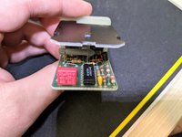
I've opened both of the N40 relays that were tried in my set up several times. To my untrained eyes there are no signs of burning. Here are close ups of one of them:

1622482549418.jpeg
1622482589718.jpeg
1622482600779.jpeg
1622482611090.jpeg
1622482658649.jpeg
 
I've opened both of the N40 relays that were tried in my set up several times. To my untrained eyes there are no signs of burning. Here are close ups of one of them:

View attachment 131700
View attachment 131701
View attachment 131702
View attachment 131703
View attachment 131704
Great! It looks pretty good to me and I note that there is a diode on the board so maybe that diode is what is saving you from the short circuit condition. Maybe. Otherwise I see ok looking transistors, resistors and capacitors on there. Also there is an MC3302 IC which is just a quad op-amp / comparator IC. The MC3302 is probably the thing that is "checking" the "reference" lighting intensity from the Instrument cluster over pin 4 58d of the N40 socket and spitting out a comparable amount of intensity (voltage) over pin 2 58D of the N40 socket. Probably.

That said, I am a theory guy ---- I am not a applied-working-knowledge kind of guy so I don't know what that whitish-greyish cylinder hovering over the board is.???
 
BTW @kiev just something to keep in the back of your head so you don't drive yourself crazy when troubleshooting ----
The two rear window switches in the rear doors appear to ground to W12 THROUGH the child-lockout switch. So if the child lockout switch is not connected or IS connected and set to lockout the rear doors, then the rear window switches will never illuminate. In fact, I just checked this on my own car and indeed this is true.

1622484711457.png
 
Kiev, I'm pretty dang sure that is X6. When touching the red probe of your DMM to this terminal block and the black probe to chassis ground, are you seeing 12V with the headlights on?

Looking at the spaghetti pile of wires, I noticed that one wire seems to be a factory blue/grey wire the alarm "installer" spliced into. It looks like it runs to the blue wire of the aftermarket alarm harness, which is a negative door trigger wire (ground when door is open). This isn't correct for any alarm install, but we should see where on the vehicle it was cut.
Hi @speedy300dturbo! Where do you see the part in bold? I went through all the pictures posted of spaghetti wires and I could not identify the part in bold text. You are much better at pixel peeping than I!

BTW everyone --- I once visited @speedy300dturbo at his house Temple of w124 worship and I realized he is one of those guys who have probably forgotten more about w124s than I will ever learn..... 🤣
 
Hi @speedy300dturbo! Where do you see the part in bold? I went through all the pictures posted of spaghetti wires and I could not identify the part in bold text. You are much better at pixel peeping than I!
I circled it in orange. It looks like a factory blue/grey illumination wire, so I wonder where it got cut.

[500Eboard] PXL_20210530_222024686.jpeg

Speedy, would you be kind enough to explain the bolded part in housewife's terms? Thanks
Aftermarket alarms have various "trigger inputs" that cause the siren to sound. These triggers are typically ground signals. For example, the contact switches at the front and rear doors are open (not grounded) when the doors are shut. When you open a door, the switch closes and completes a ground circuit, which turns on the dome light and /or triggers the alarm if armed.

When your aftermarket alarm was installed, the blue wire running to the white connector would cause the siren to blare if it became grounded (via the door contact switches) but I'm not sure why the "installer" spliced into what looks like a factory blue/grey wire!
 
I circled it in orange. It looks like a factory blue/grey illumination wire, so I wonder where it got cut.

View attachment 131743


Aftermarket alarms have various "trigger inputs" that cause the siren to sound. These triggers are typically ground signals. For example, the contact switches at the front and rear doors are open (not grounded) when the doors are shut. When you open a door, the switch closes and completes a ground circuit, which turns on the dome light and /or triggers the alarm if armed.

When your aftermarket alarm was installed, the blue wire running to the white connector would cause the siren to blare if it became grounded (via the door contact switches) but I'm not sure why the "installer" spliced into what looks like a factory blue/grey wire!
Good stuff. @kiev I had a thought since from @speedy300dturbo’s and your travails, so much of the crap aftermarket wiring you deleted seems to be in the left side of the driver’s footwell ....... How does the wiring behind the lightswitch look? Have you dropped the left knee bolster to take a look?

I refer to post 208. Note E20, Exterior Light Switch Illumination, seems also to be driven by pin2 58D of the socket for N40. Does your exterior headlight switch and all the icons around it light up?
 
I had to take a break from the electricals. From hours of staring at all the wiring, trying to take it in and process, it came to my seeing intense dreams on the subject matter. Thankfully my headliner has been completed (took a guy 3 months 😱) so this week I spent available time to install it and B pillars that have also been refurbished.

To get a few things out of the way:
I circled it in orange. It looks like a factory blue/grey illumination wire, so I wonder where it got cut.
I don't think it's it. While it looks similar to a blue/get factory illumination cable, in person it differs from it.

How does the wiring behind the lightswitch look? Have you dropped the left knee bolster to take a look?
Factory. Untouched. Knee bolster has been dropped since early on. I spent at least a few hours with my head in the driver foot well, face up with a headlight staring and starting at all of the wiring - nothing else looks molested. Overall, while the wiring looks its age, it's in good condition: no cracking or fraying anywhere...

Does your exterior headlight switch and all the icons around it light up?
No! But if I turn on my rear fog lights the red light in the headlight switch comes on.


Now, onto today. After completing major chunk of headliner/b pillars, I took a fresh look at the electrics. I'm now 99.7% convinced that X6/1 is combined with X6 on V8 models. It's located in the depth, behind the ashtray. There's a sheath with 6+ blue/gray cables (red arrow) connected to it. I've disconnected all of the connections (There are only 5) to X6/1 and did a few tests
PXL_20210605_005510062~3.jpg

***Test 1.

Power a tie of 6 or so blue/great cables (red arrow) with a positive terminal of a 9 volt battery and connecting negative terminal of the 9 volt battery to a W12 ground - window switcheS light up!

***Test #2.

Positive terminal of 9 volt battery to N40 connector's pin 2 (58D), negative terminal of 9 volt battery to W12 ground. Then check if there's voltage on any of the disconnected from X6/1 connectors. The one to which a purple arrow points, if I connect a positive lid of the voltmeter to it and a negative lid of the voltmeter to W12 ground, I get 9 volts!

Connecting just connection with a purple arrow which has 9 volts on it to just a connection with a red arrow (a tie of a bunch of blur/grey cables) doesn't light up any switches

@Jlaa, mate, help me figure out what this all means? Thanks!
 
Last edited:
[Does your exterior headlight switch and all the icons around it light up?]
No! But if I turn on my rear fog lights the red light in the headlight switch comes on.
Well well well! This is as we expected. Look at the 1st diagram in post 208. The illumination for the Exterior Lamp Switch, which is fed by a GY/RD wire from X6/1, is not lighting up! Just like everything else being fed by X6/1.

Now, onto today. After completing major chunk of headliner/b pillars, I took a fresh look at the electrics. I'm now 99.7% convinced that X6/1 is combined with X6 on V8 models. It's located in the depth, behind the ashtray. There's a sheath with 6+ blue/gray cables (red arrow) connected to it. I've disconnected all of the connections (There are only 5) to X6/1 and did a few tests
View attachment 131944

***Test 1.

Power a tie of 6 or so blue/great cables (red arrow) with a positive terminal of a 9 volt battery and connecting negative terminal of the 9 volt battery to a W12 ground - window switcheS light up!

***Test #2.

Positive terminal of 9 volt battery to N40 connector's pin 2 (58D), negative terminal of 9 volt battery to W12 ground. Then check if there's voltage on any of the disconnected from X6/1 connectors. The one to which a purple arrow points, if I connect a positive lid of the voltmeter to it and a negative lid of the voltmeter to W12 ground, I get 9 volts!

Connecting just connection with a purple arrow which has 9 volts on it to just a connection with a red arrow (a tie of a bunch of blur/grey cables) doesn't light up any switches

@Jlaa, mate, help me figure out what this all means? Thanks!
Wow now that's just so weird isn't it?!?!? I don't know exactly what's going on, but I can ask you to run another cycle of what seems to be a never-ending cycle of tests until we get to a point where you may stumble on what the true problem is! I mean, you've gotten SO FAR already! And you've made so much progress. Let me re-label your diagram:

[500Eboard] PXL_20210605_005510062~3.jpeg

So your finding is that when you power N40 socket terminal 2 (58D) with the + term of a 9v battery and connect w12 to the - term of the 9v battery, that B shows nine volts!

Question 0 - When you are powering N40 socket term 2 (58D) w/ the 9v battery, what do points C, D, and E show on the the multimeter?

Further, your secondary finding is that when you connect the + term of a 9v battery to A and the - term of the 9v battery to W12, that your window switches light up.

But, your third finding is that connecting A & B while powering N40 socket terminal 2 (58D) with the + term of a 9v battery and connecting w12 to the - term of the 9v battery results in nothing happening??!!?!? Question 1 - when this is happening, what does the multimeter say? Does the union of A & B meter out at 9v relative to W12, or is it shorted to W12?

Question 2 - Is B going to the Left & Right Air Nozzle and the illumination light for the headlamp switch?
Note that the diagrams in post 208 show only these three things as using GY/RD wires. Try a 9v battery on B. What happens?

Question 3 - Is C going to the gearshift light bulb? Note the diagrams in post 208 show this as using a GY/BU wire. Try a 9v battery on C.

Question 4 - Is E going to the rear dome lamp switch illumination? Note the diagrams in post 208 show this as using a GY/BU wire. Try a 9v battery on E.

Question 5 - What the heck does D lead to? Does that show a BR/GY wire? I don't see any BR/GY wires on the wiring diagram going to x6/1 (although I see them going to other stuff like rear door switches & door light wiring)!!!! And of course this is not the first time the wiring diagram is wrong. Is this from pin 2 (58D) of the N40 socket? What happens when you use the multimeter to test for continuity between D and pin 2 (58D) of the N40 socket? How about continuity between D and ground? :shock: What happens when you try a 9v battery on D (do not do this if D is ground!)? Measure all this with point D both with all doors closed and doors open.

Question 6 - What happens if we try to rule out the crazy possibility that a bulb might be shorting inside the socket? What happens if you REMOVE the light bulbs in Left Air Nozzle, Right Air Nozzle, the panel that houses the headlight switch that lights up all the little icons, and the gearshifter? Does anything change when you remove those four light bulbs and you do test 1, 2, and 3 again?
 
Last edited:
@Jlaa, mate, I just sat down into my car and will go through your tests, but very quickly. That test #1 that I did a few days ago. I just tried it again, and I realized this: if I put NEGATIVE terminal of the 9 volt battery to a connection that has several Blu/grey cables in it (you marked it "A") and a POSITIVE terminal of 9 volt battery to ground W12 then switches light up. If I reverse terminals switches don't light up.... This isn't normal, right? This is probably why connection "B" that reads 9 volts can't power "A"....

Also, measuring connection "B" with voltmeter, if I put voltmeter's positive lid to "B" and negative to W12 ground, I get -9 volts. If I reverse lids, so that positive lid of voltmeter is to W12 ground I get normal 9 volt reading, without minutes sign... An I ignorant or is this a tangible anomaly?
 
Last edited:
The two rear window switches in the rear doors appear to ground to W12 THROUGH the child-lockout switch. So if the child lockout switch is not connected or IS connected and set to lockout the rear doors, then the rear window switches will never illuminate. In fact, I just checked this on my own car and indeed this is true.
Yeah, can confirm on my end as well, thanks!
 
@Jlaa, mate, I just sat down into my car and will go through your tests, but very quickly. That test #1 that I did a few days ago. I just tried it again, and I realized this: if I put NEGATIVE terminal of the 9 volt battery to a connection that has several Blu/grey cables in it (you marked it "A") and a POSITIVE terminal of 9 volt battery to ground W12 then switches light up. If I reverse terminals switches don't light up.... This isn't normal, right? This is probably why connection "B" that reads 9 volts can't power "A"....
The window switches have LEDs in them for illumination. LEDs have polarity --- hook them up backwards and then won't light up. What you have established is that in order for the window switches to light up A needs to have LESS voltage potential than W12. In essence, you have established that a negative voltage will work.

What we don't know is if:
  1. the car is designed this way (seems odd) OR
  2. if somehow something in your car is swapped around.
However this doesn't explain why the other illumination is not lighting ---- like the air nozzles, gearshift indicator, icons around the headlamp switch ---- those are incandescent bulbs (I'm assuming someone has not put LEDs in here). Incandescent bulbs light up whether they are wired in forward or backwards and they do not have any polarity. Can you please put the "negative window switch illumination" finding aside for a while and continue with all those other tests to see what you find?


Also, measuring connection "B" with voltmeter, if I put voltmeter's positive lid to "B" and negative to W12 ground, I get -9 volts. If I reverse lids, so that positive lid of voltmeter is to W12 ground I get normal 9 volt reading, without minutes sign... An I ignorant or is this a tangible anomaly?
You are saying B meters out at -9v (NEGATIVE nine volts)? Under what circumstance please? How is the 9v battery connected when B meters out at -9v? This is a very important piece of information. Are you sure you do not have the test leads in your multimeter plugged in with the wrong polarity?


Yeah, can confirm on my end as well, thanks!
Good.
 
Oh Lord!! I'm feeling cracked out!! 😆 Boy is this fun!!

So, if I connect negative(!!) lid of the 9 Volt battery to pin 2 (58D) and a positive lid of same 9 volt battery to ground W12 and then connect just "B" to just "A" - window switches light up!!! :slosh:

Also, negative terminal of 9 volt battery to respective wires below and a positive(!!) to ground(!!) W12:

C - lights up fader
E - lights gear shift illumination
D - lights up rear headrest switch (but not rear dome light)

I'll do more tinkering/test to secure my findings in regards to side vents illumination. Because I'm doing tests from passenger seat and it's possible passenger vent bulb is out and I can't see driver side vent because I have instrument cluster out and blocking my view. Center vent was always illuminating, but isn't now, but perhaps a bulb gave out...
 
You are saying B meters out at -9v (NEGATIVE nine volts)? Under what circumstance please? How is the 9v battery connected when B meters out at -9v? This is a very important piece of information. Are you sure you do not have the test leads in your multimeter plugged in with the wrong polarity?
When a positive (+) terminal of 9 volt battery is connected to pin 2 (58D) and a negative terminal of same battery connected to ground W12, "B" meters out negative 9 volts if red lid of voltmeter is connected to "B" and negative lid of voltmeter is connected to ground W12

Black lid of voltmeter goes to COM, right?
PXL_20210606_182012665.jpg
 
Oh Lord!! I'm feeling cracked out!! 😆 Boy is this fun!!

So, if I connect negative(!!) lid of the 9 Volt battery to pin 2 (58D) and a positive lid of same 9 volt battery to ground W12 and then connect just "B" to just "A" - window switches light up!!! :slosh:
This begs the question (and I do not know the answer) --- is:
  1. pin2 (58D) of the N40 relay designed to spit out NEGATIVE VOLTAGE? or is
  2. something in your car hooked up backwards / reversed?
Also, negative terminal of 9 volt battery to respective wires below and a positive(!!) to ground(!!) W12:

C - lights up fader
The Fader I think is an LED, so I think polarity matters.

E - lights gear shift illumination
I think the gear shift is an incandescent bulb, so I think polarity shouldn't matter with E. You might want to confirm.
D - lights up rear headrest switch (but not rear dome light)
The rear headrest switch I think is an LED, so I think polarity matters.
I'll do more tinkering/test to secure my findings in regards to side vents illumination. Because I'm doing tests from passenger seat and it's possible passenger vent bulb is out and I can't see driver side vent because I have instrument cluster out and blocking my view. Center vent was always illuminating, but isn't now, but perhaps a bulb gave out...
Yeah--- still have to get the air nozzle(s) illumination and headlightlight switch icons working ---- but look on the bright side ---- YOU ARE MAKING PROGRESS!!!!!!!!! At least you know the wiring is in tact ... just ....... opposite?!?!?!

When a positive (+) terminal of 9 volt battery is connected to pin 2 (58D) and a negative terminal of same battery connected to ground W12, "B" meters out negative 9 volts if red lid of voltmeter is connected to "B" and negative lid of voltmeter is connected to ground W12
Dang that is so weird. That makes me think there is something in the wiring IN BETWEEN pin2 (58D) of the N40 socket and x6/1. Or something hooked up there that shouldn't be. So confusing.

Black lid of voltmeter goes to COM, right?
View attachment 132005
This is correct. Hang in there @kiev. You are getting closer!
 
So! I plugged N40 connector into N40 relay, reconnected battery, turned on lights and connected just "B" to just "A" - window switches light up!!! So negative voltage is by design then. However, if I nail (screw) "A" and "B" to X6-X6/1 combo window switches don't light up!!

Looking at X6-X6/1 and feeling behind it, I don't see/feel anything. It appears to be just a mounting point...(?) Otherwise, it appears to be shorted...

Screenshot_20210606-145616.png
 
So! I plugged N40 connector into N40 relay, reconnected battery, turned on lights and connected just "B" to just "A" - window switches light up!!! So negative voltage is by design then.
Yes!!! Progress!!!!

However, if I nail (screw) "A" and "B" to X6-X6/1 combo window switches don't light up!!

Looking at X6-X6/1 and feeling behind it, I don't see/feel anything. It appears to be just a mounting point...(?) Otherwise, it appears to be shorted...
Can you isolate the leg that appears to be causing the short? Can you disconnect everything at X6-X6/1 and then just connect A and B BY ITSELF (meaning not connect A and B to X6-X6/1 .... just connect A&B together with some tape) ......and turn the lights on and watch the window switches light ...... and then slowly reconnect the other legs one at a time WITH TAPE and see what happens ?

This way you can isolate if the short is on one of the other legs C D E or if the short is somehow within the X6-X6/1 point itself .....

 
Can you isolate the leg that appears to be causing the short? Can you disconnect everything at X6-X6/1 and then just connect A and B BY ITSELF (meaning not connect A and B to X6-X6/1 .... just connect A&B together with some tape) ......and turn the lights on and watch the window switches light ...... and then slowly reconnect the other legs one at a time WITH TAPE and see what happens ?
So for now, I have everything that WAS connected to X6-X6/1 disconnected. If I connect "A" and "B" in my hands window switches light up. If transfer A+B connection to X6-X6/1 window switches no longer light up. That's why I'm preliminary thinking the issue is straight up with X6-X6/1 even though it appears to be just a mounting point, so I'm not sure how can it be shorted out....

I'll be back 😀
 
Is it possible to physically remove connector X6-X6/1 so it's "free-air", and connect the wires to it?

Almost acts like X6-X6/1 is somehow shorted to ground but doesn't appear that way in the photos. Weird.
 
Is it possible to physically remove connector X6-X6/1 so it's "free-air", and connect the wires to it?

Almost acts like X6-X6/1 is somehow shorted to ground but doesn't appear that way in the photos. Weird.
I wonder if the bolt next to x6-x6/1 is grounded? I wonder if the A B C D E wires are somehow shorting out on the bolt? Maybe :
  • Multimeter - test for continuity between X6-x6/1 and W12
  • Multimeter - test for continuity between X6-x6/1 and the adjacent "red" bolt

In that way you can determine if x6-x6/1 is indeed somehow physically shorted to ground, of it the problem somehow is if wires A B C D E are grounding out on something when they are bent in such a way to make a physical connection to x6-x6/1.


[500Eboard] Screenshot_20210606-145616.png[500Eboard] 117.jpg
[500Eboard] PXL_20210605_005510062~3.jpeg
 
I connected all 5 connectors that were connected to X6-X6/1 to each other like so. X6-X6/1 is OUT of the loop
Screenshot_20210606-155026.png

Then went to turn the lights on. (I am missing one bulb in the left most vent):
 
Last edited:
Based on the updates that Kiev has posted so far, it sounds like one of the illumination wires may be shorted to ground. This could happen if the connector pins in a bulb socket get bungled and somehow touch each other. Look very carefully at the square air vent bulb socket. You can also pull back the heat-shrink tubing on the wire side of the connector by a millimeter or so and probe for continuity (which you should NOT have) at the solder joint.
 
I connected all 5 connectors that were connected to X6-X6/1 to each other like so. X6-X6/1 is OUT of the loop:
View attachment 132011

Then went to turn the lights on. (I am missing one bulb in the left most vent):
HALLELUJAH! So the lights light up when x6-x6/1 is out of the loop! SWEET progress!!!!
Can you use your mutlimeter to test for continuity between x6-x6/1 and ground (w12) WITHOUT any wires connected to x6-x6/1?
 
Based on the updates that Kiev has posted so far, it sounds like one of the illumination wires may be shorted to ground. This could happen if the connector pins in a bulb socket get bungled and somehow touch each other. Look very carefully at the square air vent bulb socket. You can also pull back the heat-shrink tubing on the wire side of the connector by a millimeter or so and probe for continuity (which you should NOT have) at the solder joint.
@speedy300dturbo that is a good theory --- I think @kiev ruled out the possibility that one of the illumination wires is shorted to ground though ---- check out the lastest video he posted when he took x6-x6/1 out of the circuit (one minute before you uploaded your comment)?
 
I wonder if the bolt next to x6-x6/1 is grounded?
Yeap, the bolt is grounded, but X6-X6/1 itself doesn't appear to be. I'm so content but drained after the burst endorphins earlier today.
 
Just installed a missing gear selector illumination bulb and a burned out center vent rotary wheel bulb. Now every. single. bulb. works. Since day one of my ownership (August 2014) ONLY climate unit (all of its switches and dials), air recirculation, hazard lights, rear defroster, and center vent rotary wheel illuminated. Everything else was dark. Made for quite a grim interior ambiance.

I had no idea driver seat memory, sunroof switch and around headlight knob modes actually could be illuminated 💡💡💡. Feels like a totally different cabin now - wow!!!

@Jlaa, without you this wouldn't have happened. Thanks for patiently babysitting me through this whole process. I've learned a lot.... of basic electrical knowledge and then some 🙂. @gsxr, you've mostly sited this one out, but I know you were pulling for me - so thank you! 🙂. @speedy300dturbo, thank you as well for your attempts to help out!

1623730507371.jpeg

🎄🎄🎄🎄🎄:
 
Congratulations @kiev! You did it all yourself! We just all collectively helped keep you in track. I am sure you now are experiencing euphoric levels of satisfaction from self-fixing this 7 year irritant. Bravo!👏. And the best part was that you got to delete all that crap 💩 aftermarket wiring!
 

Who has viewed this thread (Total: 1) View details

Who has watched this thread (Total: 1) View details

Back
Top