EDIT: I wrote this for O-ring replacement, but the same information applies to replacing the entire control pressure cable assembly, since it needs to be removed anyway. Thread title updated.
This is not a step-by-step traditional HOW-TO, but rather a general description with some tips & tricks, along with the factory procedure from the WIS (not available in the CD-ROM). PDF attached.
Part numbers:
First, I would NOT recommend attempting this unless:
With that out of the way, here is some background on this problem: When the control pressure cable O-ring leaks, the transmission will lose fluid slowly over time. For example, when parked all year due to COVID. The fluid level can get low enough so that the transmission will flare badly or encounter a false neutral when driving, particularly when cold. When the fluid level is low enough (down ~2 quarts), the transmission may not engage gears at all, or require revving the engine to engage. If this happens, add just enough fluid to allow moving the car if necessary (i.e., driving into your garage), but don't fill it... because you'll have to drain the pan anyway. No point in adding 2+ quarts that you'll drain out immediately.
I'm also assuming you have done due diligence, and confirmed that the leak really is from the control pressure cable (edit: or, that the control pressure cable is faulty and needs replacement). The transmission must be completely de-greased / de-oiled, and driven enough to verify the exact leak point. Wrapping a clean paper towel around the base of the control pressure cable plastic, where it touches the transmission housing, will help positively identify the source. If the B1 and B2 covers are dry, and the dipstick is too, the lower edge will be dry and red ATF will only appear at the control pressure cable area.
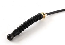
Before lifting the car, disconnect the end of the control pressure cable from the throttle linkage behind the airbox, and remove the C-clip which holds the cable in the bracket. Lift up the rubber boot and release the cable from the bracket, so you can pull the cable down to the bottom of the engine, and allow complete removal of the control pressure cable assembly. The cable may have a plastic clip attaching it to the vacuum pipe, if so, remove the clip. Now lift the car and begin disassembly underneath.
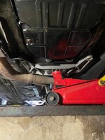
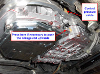
Access in the transmission tunnel area is extremely tight on the W124 with M119. To make more room, you must pry the transmission sideways towards the driver side. It does not move much, maybe 1 inch total, but every little bit helps. I loosened the exhaust crossover pipe so it flops around but still has bolts in place, and also loosened the bolts at the passenger exhaust manifold to allow the catalyst pipe to also move freely. This will keep the exhaust system from restricting movement as you pry the transmission to the side. The rear exhaust bracket from transmission to catalyst pipe should be removed, along with the rear transmission mount support bracket. The transmission will lower down and the driveshaft will sit on the chassis support brace. If you need more room to fit your hands around the control pressure cable, unbolt the flex disc from the rear of the transmission; this will let the trans drop down even further... be careful, other things may bind and the engine tilts backwards, don't force it down.
With the transmission lowered and pushed sideways, clean the area around the control pressure cable as best you can using solvent, rags, screwdrivers to scrape gunk, small wire brushes, compressed air, whatever you can do to clean it as much as possible. If the transmission tunnel insulation is badly swollen or (in extreme cases) soaked in ATF, cut or tear the insulation away between the trans tunnel wall and the plastic body of the control pressure cable. You don't want debris falling into the hole during R&R. Long needle nose pliers can be used to tear away insulation if necessary.
Drain the transmission pan. If possible let the car sit overnight after draining, you'll get another pint out the next morning. The pan does not need to come off yet. To remove the control pressure cable, follow the directions in the PDF. The locking tab shown in the diagram for step 1 must be pushed upward, this will allow the control pressure cable body to rotate away from the transmission (step 2). It only has to rotate enough to allow the assembly to move vertically upward, maybe rotate 30° or so. Push the whole assembly straight up to remove; the linkage rod should disconnect itself. Extract it from the car and clean it thoroughly. Don't lose the plastic cap for the top vent (#12 in the diagram), this can be held in place with RTV or similar adhesive if it is loose. Ignore all the adjustments mentioned in the PDF unless you are installing a new (or different) control pressure cable assembly.
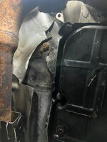
With the control pressure cable out, use a mirror to see how clean the bore is where the O-ring seats. This is extremely difficult to clean. I stuffed clean paper towels into the hole and first cleaned the area around the hole, so no more debris would fall in. With the external area around the bore cleaned, remove the paper towel plug and clean the inside of the hole. I used solvent-soaked Q-tips with long-handle 90° needle-nose pliers repeatedly until the bore was clean. If a SMALL amount of dust or dirt falls into the hole, don't worry about it, that's what the filter is for. A few specks are not a big deal. If a large amount falls inside, you'll have to drop the valvebody to clean it out, as the debris will sit on the top corner of the VB where you can't access it with the pan removed.
After the transmission housing and bore is clean, and control pressure cable plastic body clean, you are ready to re-install the control pressure cable. Slide a new O-ring (MB # 016-997-04-48) on the control pressure cable body, apply some ATF to lubricate it. As mentioned in step 5 of the PDF, pull the black plastic plunger as far down as possible (item #2 in the diagram). It will poke out the bottom maybe 1/2 inch (10mm) and you will feel a click as there is a detent which holds it in this "assembly position". With a mirror, try to place the metal linkage rod in the location needed to match the guide slot and hole in the black plastic plunger. See attached photos of the bore and linkage rod. Don't forget to connect the vacuum hose as you move the assembly into position, it will be very difficult to connect afterwards.
When you slide the control pressure cable down into the transmission bore, the metal rod SHOULD fall into place. Push the plastic body all the way down until it seats on the aluminum housing. Pull on the ball end of the cable and verify it feels normal, and the ball end pulls back from spring pressure inside the transmission. If not, remove and try again, pulling the plunger into the assembly position each time. You may need to drop the transmission pan and push on the metal lever to force the linkage rod to pop further up. Repeat as needed until you are positive the linkage is attached correctly.
With the linkage attached inside the transmission, rotate the plastic body towards the transmission, and swing the metal locking tab down that holds it in place. Re-install whatever else had been disconnected (exhaust, brackets, trans mount, etc). Re-attach the ball socket to the throttle linkage, re-install the vacuum line clip if removed. Torque the transmission pan to spec if it was removed, replace pan gasket as needed. Measure the amount of fluid drained and pour in the same amount, if you don't know how much was drained, start with 2 quarts (assuming the pan was drained completely, even if not removed) and slowly add fluid with the engine running until it's at least showing at the bottom of the dipstick. Adjust fluid level same as you would after a fluid & filter change.
Use the contents from the newly-filled swear jar to buy a 12-pack of your favorite frosty beverage, and contemplate what sadist engineered this contraption.


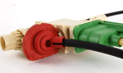
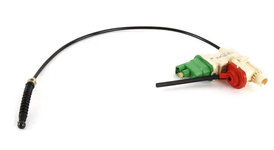
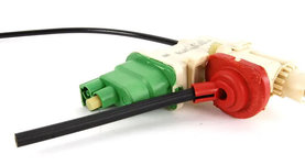
Note: In the photos, the green plastic vacuum box is for the catalyst-heating cold upshift delay. The small red plastic box is for the E/S (Economy/Standard) program selector which was not offered in USA. Only the control pressure cable assembly with BOTH the green and red sections is sold now. Your old one on a USA-spec car may only have the green plastic, as shown in the photo below on an original 1994 E500 transmission. The red plastic vacuum port should be sealed off if not used.
This is not a step-by-step traditional HOW-TO, but rather a general description with some tips & tricks, along with the factory procedure from the WIS (not available in the CD-ROM). PDF attached.
Part numbers:
140-270-05-73 = Control pressure cable assembly ($159 MSRP, Dec-2020)
016-997-04-48 = O-ring ($1.70 MSRP, Dec-2020)
First, I would NOT recommend attempting this unless:
1) You have a lift, or other means of getting the car pretty high off the ground. This job will be sheer misery if you cannot stand underneath the vehicle.
2) You are 110% certain that absolutely every other seal on the transmission is not leaking and/or are somewhat recent. If not, remove the transmission and re-seal everything, not just the control pressure cable. The seals are cheap and removing the transmission is easier than attempting to replace most seals with the trans in the car.
With that out of the way, here is some background on this problem: When the control pressure cable O-ring leaks, the transmission will lose fluid slowly over time. For example, when parked all year due to COVID. The fluid level can get low enough so that the transmission will flare badly or encounter a false neutral when driving, particularly when cold. When the fluid level is low enough (down ~2 quarts), the transmission may not engage gears at all, or require revving the engine to engage. If this happens, add just enough fluid to allow moving the car if necessary (i.e., driving into your garage), but don't fill it... because you'll have to drain the pan anyway. No point in adding 2+ quarts that you'll drain out immediately.
I'm also assuming you have done due diligence, and confirmed that the leak really is from the control pressure cable (edit: or, that the control pressure cable is faulty and needs replacement). The transmission must be completely de-greased / de-oiled, and driven enough to verify the exact leak point. Wrapping a clean paper towel around the base of the control pressure cable plastic, where it touches the transmission housing, will help positively identify the source. If the B1 and B2 covers are dry, and the dipstick is too, the lower edge will be dry and red ATF will only appear at the control pressure cable area.
Before lifting the car, disconnect the end of the control pressure cable from the throttle linkage behind the airbox, and remove the C-clip which holds the cable in the bracket. Lift up the rubber boot and release the cable from the bracket, so you can pull the cable down to the bottom of the engine, and allow complete removal of the control pressure cable assembly. The cable may have a plastic clip attaching it to the vacuum pipe, if so, remove the clip. Now lift the car and begin disassembly underneath.
Access in the transmission tunnel area is extremely tight on the W124 with M119. To make more room, you must pry the transmission sideways towards the driver side. It does not move much, maybe 1 inch total, but every little bit helps. I loosened the exhaust crossover pipe so it flops around but still has bolts in place, and also loosened the bolts at the passenger exhaust manifold to allow the catalyst pipe to also move freely. This will keep the exhaust system from restricting movement as you pry the transmission to the side. The rear exhaust bracket from transmission to catalyst pipe should be removed, along with the rear transmission mount support bracket. The transmission will lower down and the driveshaft will sit on the chassis support brace. If you need more room to fit your hands around the control pressure cable, unbolt the flex disc from the rear of the transmission; this will let the trans drop down even further... be careful, other things may bind and the engine tilts backwards, don't force it down.
With the transmission lowered and pushed sideways, clean the area around the control pressure cable as best you can using solvent, rags, screwdrivers to scrape gunk, small wire brushes, compressed air, whatever you can do to clean it as much as possible. If the transmission tunnel insulation is badly swollen or (in extreme cases) soaked in ATF, cut or tear the insulation away between the trans tunnel wall and the plastic body of the control pressure cable. You don't want debris falling into the hole during R&R. Long needle nose pliers can be used to tear away insulation if necessary.
Drain the transmission pan. If possible let the car sit overnight after draining, you'll get another pint out the next morning. The pan does not need to come off yet. To remove the control pressure cable, follow the directions in the PDF. The locking tab shown in the diagram for step 1 must be pushed upward, this will allow the control pressure cable body to rotate away from the transmission (step 2). It only has to rotate enough to allow the assembly to move vertically upward, maybe rotate 30° or so. Push the whole assembly straight up to remove; the linkage rod should disconnect itself. Extract it from the car and clean it thoroughly. Don't lose the plastic cap for the top vent (#12 in the diagram), this can be held in place with RTV or similar adhesive if it is loose. Ignore all the adjustments mentioned in the PDF unless you are installing a new (or different) control pressure cable assembly.
With the control pressure cable out, use a mirror to see how clean the bore is where the O-ring seats. This is extremely difficult to clean. I stuffed clean paper towels into the hole and first cleaned the area around the hole, so no more debris would fall in. With the external area around the bore cleaned, remove the paper towel plug and clean the inside of the hole. I used solvent-soaked Q-tips with long-handle 90° needle-nose pliers repeatedly until the bore was clean. If a SMALL amount of dust or dirt falls into the hole, don't worry about it, that's what the filter is for. A few specks are not a big deal. If a large amount falls inside, you'll have to drop the valvebody to clean it out, as the debris will sit on the top corner of the VB where you can't access it with the pan removed.
After the transmission housing and bore is clean, and control pressure cable plastic body clean, you are ready to re-install the control pressure cable. Slide a new O-ring (MB # 016-997-04-48) on the control pressure cable body, apply some ATF to lubricate it. As mentioned in step 5 of the PDF, pull the black plastic plunger as far down as possible (item #2 in the diagram). It will poke out the bottom maybe 1/2 inch (10mm) and you will feel a click as there is a detent which holds it in this "assembly position". With a mirror, try to place the metal linkage rod in the location needed to match the guide slot and hole in the black plastic plunger. See attached photos of the bore and linkage rod. Don't forget to connect the vacuum hose as you move the assembly into position, it will be very difficult to connect afterwards.
When you slide the control pressure cable down into the transmission bore, the metal rod SHOULD fall into place. Push the plastic body all the way down until it seats on the aluminum housing. Pull on the ball end of the cable and verify it feels normal, and the ball end pulls back from spring pressure inside the transmission. If not, remove and try again, pulling the plunger into the assembly position each time. You may need to drop the transmission pan and push on the metal lever to force the linkage rod to pop further up. Repeat as needed until you are positive the linkage is attached correctly.
With the linkage attached inside the transmission, rotate the plastic body towards the transmission, and swing the metal locking tab down that holds it in place. Re-install whatever else had been disconnected (exhaust, brackets, trans mount, etc). Re-attach the ball socket to the throttle linkage, re-install the vacuum line clip if removed. Torque the transmission pan to spec if it was removed, replace pan gasket as needed. Measure the amount of fluid drained and pour in the same amount, if you don't know how much was drained, start with 2 quarts (assuming the pan was drained completely, even if not removed) and slowly add fluid with the engine running until it's at least showing at the bottom of the dipstick. Adjust fluid level same as you would after a fluid & filter change.
Use the contents from the newly-filled swear jar to buy a 12-pack of your favorite frosty beverage, and contemplate what sadist engineered this contraption.
Note: In the photos, the green plastic vacuum box is for the catalyst-heating cold upshift delay. The small red plastic box is for the E/S (Economy/Standard) program selector which was not offered in USA. Only the control pressure cable assembly with BOTH the green and red sections is sold now. Your old one on a USA-spec car may only have the green plastic, as shown in the photo below on an original 1994 E500 transmission. The red plastic vacuum port should be sealed off if not used.
Attachments
-
27-115B_R+R_Control_Pressure_Cable.pdf101.5 KB · Views: 46
-
 tranny05_722.370.jpg157.9 KB · Views: 81
 -
 bowden_cable_bore1.jpg115.9 KB · Views: 71
 -
 bowden_cable_bore2.jpg115.3 KB · Views: 60
 -
 cable1.jpg17.3 KB · Views: 60
 -
 cable2.jpg35.9 KB · Views: 57
 -
 cable3.jpg14.3 KB · Views: 54
 -
 cable4.jpg28 KB · Views: 52
 -
 MB_140-270-05-73.jpg68.5 KB · Views: 60
 -
 cable5.jpg27.3 KB · Views: 55
 -
 valvebody.jpg114.7 KB · Views: 80