• Hi Guest !

    Welcome to the 500Eboard forum.

    Since its founding in late 2008, 500Eboard has become the leading resource on the Internet for all things related to the Mercedes-Benz 500E and E500. In recent years, we have also expanded to include the 400E and E420 models, which are directly related to the 500E/E500.

    We invite you to browse and take advantage of the information and resources here on the site. If you find helpful information, please register for full membership, and you'll find even more resources available. Feel free to ask questions, and make liberal use of the "Search" function to find answers.

    We hope you will become an active contributor to the community!

    Sincerely,
    500Eboard Management

HOW-TO: Replacing M119 camshaft oiler tubes

BTW, are there any audible signs (or other) wo removing the valve cover to know if these are in pieces?
Usually, there are no symptoms, audible or otherwise... unless things get really bad. I've seen some where it appears the chain was rubbing the underside of the valve cover, possibly from broken rails allowing the chain to deviate from the normal path.

:duck:
 
Folks, do anyone can give an advice from his humble POV?
I understand that is not good to drive while having this issue but waiting for the spare parts and car is of vital importance rn.
How many time is acceptable to drive ? Based on the experience or maybe some other recommendations about rpms maybe ... for not to do worse.
My regards!
 
To update this post (because of it's importance and being common) the www/124-zone links are not working so this is the PDF of what was found on that page.
IT IS IMPORTANT BECAUSE, depending on your M119 there are at least 2 different valve cover bolts AND 3 different ones for early models:
I will post the PDF link-
 

Attachments

Hi, I’d appreciate some advice please. My 97 SL500 has 103k miles on it, and the engine is normally smooth and quiet. 10 miles ago it developed a distinct tappetty noise - a regular tick, suggesting it was one lifter not pumping up. I was even a little pleased as it gave me a valid reason to do the long planned metal oiler tube replacement. New seals, gaskets, breather hoses and the top chain guides, and this very helpful guide, all ready to go.

I have pulled the cam covers. There’s various mentions of plastic tubes “blowing” and the like here; I didn’t really know what I expected - I doubt any tubes will rupture or similar - but everything looks worryingly normal. A few of the plastic tubes wobble very slightly, but I believe the metal ones may do that too. The old O rings on the metal tubes seemed pretty tired and flat, compared to the MB new items, and I daresay the seals on this engine may well be similarly tired - I have yet to pull any plastic tubes as I’m a little deflated!

I am concerned I do all this work and the problem persists. Is the tappetty noise = oiler tubes diagnosis infallible or should I be checking anything else while I’m in here? Is the issue the plastic tubes MAY give way but at this mileage the tube O rings will be tired and allow oil to escape the lifter?

(ETA I’ve pulled the left front oiler tube. The seals remain bright green but they barely extend beyond the surface of the plastic tube, whereas the new seals appear “plumper” on the metal tube so perhaps I’ve answered my own question!).

Many thanks

Steve
 
Last edited:
The plastic oiler tubes’ ENDS blow out, not the seals. It’s the round end of the main body of the tube that fails.

The seals don’t really fail or cause any issue.

You need to remove all of the tubes and replace them wholesale with aluminum ones. In the process of doing this you will likely find the one that has failed. The green seals again don’t really fail. But If you are replacing the tubes, it’s worth the $15 for a new set of 32 seals for the replacement tubes.
Woo hoo! Thanks Gerry, faith and enthusiasm fully restored! Rearmost tube on UK driver’s side is open at the bottom, so I can entirely see what’s wrong and how the aluminium tubes are better. New seals here and ready to go when the aluminium tubes have finished their ultrasonic bath! I have a second set for the other SL. The seals in the UK are just over £1 each plus VAT - currently one short (for the second SL) as MB placed 9 in a pack of 10, so single seal on the way from Germany!
 
@Stegel, don't forget to replace the oil separator on the passenger side (no separator on the driver's side)
Thanks, new parts here for that (driver’s side here!). I’ve also got the small square gaskets that sit on the (new) plastic guides that fasten around the chains between the sprockets. There will be nothing beneath the cam covers made of rubber or plastic original to the engine’s build when I finish, and far less plastic in total!

Thanks for everyone’s advice - I knew aluminium tubes were good, but hadn’t realised the failure mode of the plastic pipes. It must have saved just a few Euro per engine when the change was made.
 
For anyone doing this on a W140/C140..

Just did this upgrade on my 99 CL500. Again spot on article. I did find that the lower rear valve cover bolt on each side was indeed reachable both by hand and with a 1/4" torque wrench. Perhaps the Engine bay on the W140 is just slightly more roomy around the rear. Same goes for setting the Valve covers back in place, i didnt have any issues landing them first time and without having the gasket move or sit out of place.

Made a good writeup with pictures on my thread over on Benzworld too....
About halfway down the third page

20210628_231903.jpg20210629_225151.jpg

Thanks again for the info, such a great passion for those keeping these cars running

Nick
 
just adding this here in case it wasn't added so people have options for the cam cap copper crush washers;
washer dimensions: 6x10x1mm
 
I recently was able to obtain a set of used, but good condition, metal M119 camshaft oiler tubes from a 500Eboard member. I decided to begin the installation procedure and finish it up this coming week as I get the E500 prepared for the trip to MBCA's StarTech meeting in Alabama during the middle of May.

This job overall is not very hard, but it is labour-intensive and requires one to pay attention. It also requires that you have a number of parts on hand, that need to be replaced during the procedure. I would say it would take the average person about 4-5 hours to do this job, perhaps more. I spent three hours alone on the passenger side engine bank, simply because I took my time and cleaned up everything I found.

The following types of tools will be required:
  • various sizes of flat-blade screwdrivers
  • 1/4" and 3/8" ratchets, extensions
  • 11mm socket (1/4 and 3/8" sizes)
  • can or two of brake cleaner
  • 3-4 shop rags
  • flashlight or other strong light source
  • torque wrench
  • 5mm flex-head allen socket
  • 5mm regular allen socket
  • Needle-nose or standard pliers

The following MB parts* are HIGHLY recommended for this job:
  • valve cover gasket kits for left and right side engine banks (MB part numbers 119 010 13 30 and 119 010 14 30)
  • 18 copper "crush" washers for valve cover bolts (MB part number N007603 006106)
  • Replacement metal cam oiler tubes (16)
  • Upper plastic chain rail guides (MB part numbers 119 052 09 16 (two required); 119 050 03 16; and 119 050 02 16)
  • 32 new o-rings for replacement cam oiler tubes (MB part number 015 997 31 48)
*GSXR note: "MB parts" means "Genuine Mercedes" only, not aftermarket, i.e. not Victor valve cover gaskets.


Here's the procedure I followed. The first post will be for the passenger side of the engine. The second post will be for the driver's side. It's also a good idea to replace the spark plugs when you are doing this job; they are rarely so accessible. If you have more than 20K miles on your plugs, you should plan to do the plugs.

First of all, a view of the engine as the hood is opened, and with the air intake "zoom" tubes, air box and plastic vanity panel removed.
View attachment 15429 View attachment 15431


If anyone is interested, here's the solenoid setup for the nitrous-oxide injection system, that sits on the inner firewall just behind the airbox.
View attachment 15433


Next up is to remove the plastic panel that covers the distributor and cam advance solenoid. This just unclips and lifts off. Then, it's time to take a large flat-blade screwdriver, and remove the two plastic bolts that hold the ignition and spark plug wire cover to the aluminum valve covers. Photos 3 and 4 below show the plastic cover coming off, and what's underneath it.
View attachment 15435 View attachment 15437 View attachment 15439 View attachment 15441


The next step is to remove these two wiring bundles from their secured point to the top of the valve cover. The flat metal plate holds them to the valve cover, and the plate is attached by two 5mm allen head bolts, which are removed with ease. Note that one bolt is longer than the other. The longer bolt goes on the side toward the passenger compartment (firewall) - something to remember at re-assembly time.
View attachment 15443 View attachment 15445 View attachment 15447 View attachment 15449 View attachment 15451 View attachment 15453


For future reference, here's how the ignition wires are routed to the passenger-side engine bank.
View attachment 15455 View attachment 15457


Then it's time to remove the spark plug connectors, and the breather hose at the bank of the valve cover. The clamp can be squeezed together with a pair of needle nose or channel-lock pliers to release it, and then the hose can just be twisted off the fitting.
View attachment 15459 View attachment 15461


I also took the time to remove the two 5mm allen bolts that held the black plastic wire routing piece atop the cylinder head. I move then back a couple of inches toward the MAF, as shown. This was to provide more clearance/room for the next steps.
View attachment 15463


Here begins the process of removing the nine valve cover bolts. The pivoting-head 5mm 1/4" socket came in extremely handy for both the front and rear corner bolts, which would have been EXTREMELY difficult to remove otherwise. This tool is almost imperative for the job. Make sure you get it before you remove the valve covers.
View attachment 15465 View attachment 15467 View attachment 15469 View attachment 15471 View attachment 15473 View attachment 15475


Here's the bolts, laid out in the correct order on my work table. Notice that the middle bolt at the front of the motor is longer than the others.
View attachment 15477


Then, I pried loose the cam cover with a large flat-blade screwdriver and carefully removed it from the top of the cylinder head. Notice that three of the four spark plug boots stayed attached to the head, not the valve cover. These boots will be pried off and removed later. All of this rubber (boots and the valve cover gasket) was quite hard - not petrified, but very close to being rather brittle.

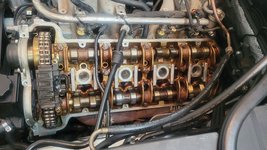
Also included are a couple of photos of the removed valve cover, and the valvetrain immediately after the cover was removed. Notice it's quite clean in there, as a result of using synthetic motor oil !!
View attachment 15479 View attachment 15481View attachment 15484


Here's a close-up of the brown plastic timing chain top slide rail.
View attachment 15486


Next, I covered the exposed area of the motor with clean rags so that it would be rather protected from airborne pollen, dust and other contaminants.
View attachment 15488


Here are the 16 replacement cam oiler tubes lined up on my work table, ready for replacement. All of the tubes have new, green, MB factory o-rings installed. This is highly advisable to do as a precaution, as older/used sets of oiler tubes will have used rubber o-rings, which can be brittle and/or petrified. I found this exactly to be the case when I removed the old rubber o-rings that came on the oiler tubes. They were quite rigid and fairly brittle.
View attachment 15490 View attachment 15493


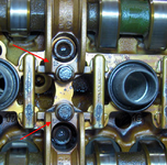
Next step is to begin removing the cam bearing caps, two at a time (one for the intake cam, the other for the exhaust cam. For three of the five towers, you will replace two cam oiler tubes when you remove the pair of bearing caps. DO NOT MIX UP THE CAPS WHEN YOU REMOVE THEM -- KEEP THEM IN THE ORDER AND ASSOCIATED WITH THE CAM THEY CAME OFF OF. The cam bearings are held on by two 11mm bolts, which are re-torqued to 10 Nm when re-installed. For the frontmost and rear-most cam bearing caps, you will only replace ONE tube each. The front-most tube also requires replacement of the plastic slide rail assembly, which will be shown a bit later.
View attachment 15494 View attachment 15496 View attachment 15498 View attachment 15501


Here is a detailed comparison of the plastic vs. metal oiler tubes. Notice that my stock plastic tubes also came from the factory with green o-rings.
View attachment 15502 View attachment 15504 View attachment 15506 View attachment 15509


Here are a few views of installing the new oiler tubes into place .... fitting them and pressing them down with a "click"
View attachment 15510 View attachment 15512 View attachment 15518


After fitting the tube(s) in place, it's time to replace that pair of cam bearing caps. Because I'm rather anal, I cleaned off the bearing surface with a rag, and then added a small dollop of assembly lube that I'd initially used on my M117 rebuild several years back, for exactly the same purpose -- to provide some initial lubrication at startup, until proper oil pressure can be built up and the oil circulates properly through the valvetrain.
View attachment 15514 View attachment 15520 View attachment 15517
Doing this right now wish me luck and thanks for the write up :D
 
6BD9BD52-374A-4097-9C89-79427172F277.jpeg5157774C-9D65-4F64-884F-54FB2A384B9E.jpeg
Just finished disassembling everything
One of the hoses is physically damaged I noticed.
And one pesky bolt was stripped from before when I changed the gasket last year.

Is the hose ok to use?
 
It isnt leaking, but getting a new one should be on your list based on age. Fuel will dry out the rubber over the decades and there is a lot of heat. Just routine things to do, a gouge in the rubber should not affect it but keep an eye. Me, I would replace the fuel hoses in the engine bay and the fuel pressure regulator. (if original) just me...

If you have a swivel attachment for that and other bolts, it is very simple to get the valve covers to seal properly without exceeding the torque spec in newton meters.
 
Update: I finished the entire job. None of my oiler tubes were broken but I changed them to aluminum anyway + the new timing chain guides.

@nocfn Are you a moderator? Please delete my 3 above messages and I will move this discussion to my other post in the M119 section of the forum.
 
Just finished disassembling everything
One of the hoses is physically damaged I noticed.
Is the hose ok to use?
That hose is OK to use. Those are a 2-ply style hose and the "dent" is only on the outer sheath. However, new hoses are generally inexpensive and replacing them would be a good idea after 30 years. It's not bulk hose, you have to buy a replacement from Mercedes. If NLA, a hose/hydraulic shop can replace the rubber hose portion and re-use the existing end fittings.


:jono:
 
I just finished this job today. Thank you Gerry for the excellent write up.

I thought I might share some of my experiences in hopes that it might help someone, like I have been helped by others here.
I assembled the parts and the tools and, this thread and, did great, until it came time to reinstall the cam covers without losing the gasket.
I expected it to take a number of tries, but it is still very frustrating by the time I got to attempt 5 or 6 on the passenger side.

I realized the issue I was having was keeping the cam cutout "half moons" clear of the cam caps before lowering the cam cover.
I was finally successful (partly) by reaching under the cam cover with a long screwdriver and pushing the lower, exhaust, half moon past the cam cap and then lowering the cam cover. To be honest, on the passenger side, I gave that half moon a slight push with the screwdriver then pushed the cover back, hard, compressing the hose that is in the way back there, and then lowering the cover.

On the driver side, I got it it one shot. (Insert self congratulations here!)

I tried to get a picture as I was in process, but it is not that clear.
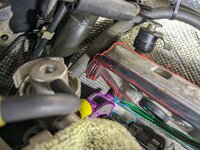
The picture below is peeking under the driver's side cam cover, at the rear.
The half moon for the exhaust cam cutout is hung up on the cam cap. It is hard to see, but there is a screwdriver blade there attempting to push it past the cam cap. What I ended up doing was lifting the cam cover towards the throttle body, positioning the exhaust half moon between the intake and exhaust cam caps, and then pushed it back and down. It dropped right into place.

So, in the end, I don't know if the screwdriver really made a huge difference. But it helped me to understand just where the problem was originating.

Your mileage may vary.


PXL_20230829_145440675.jpg
PXL_20230829_145436847~3.jpg
In an attempt to clarify things, I boogered up the picture using my fat finger on my phone screen and my 2 yr art degree to outline some of the different parts...
Cam cover gasket: red
Exhaust cam cap: blue
Intake cam cap: purple
Screwdriver blade: green
 
The next step is super-important and delicate ... the removal and replacement of the plastic sliding rail for the top of the timing chain, located between the cam sprockets. This plastic rail consists of two plastic pieces (which are rather inexpensive) that press together and are locked by six small tangs, which snap into slots. It's fairly self-explanatory once you see it. I used a couple of small flat-blade screwdrivers to release the tangs. It's a GREAT idea to place rags below the sprockets and plastic slide rail area, because you WILL break some of the tangs off in the process, and you don't want to lose these pieces of plastic down into the motor. As you can see from the photo, I broke off quite a few pieces and was able to capture them. This plastic is quite old and brittle, and is subjected to quite a lot of heat and abuse, so it's IMPORTANT that you purchase new plastic rails BEFORE you do this job. Part numbers are above. Trust me, you WILL break the plastic in the process of removing it, unless it is brand new or near new.

The large piece is held on with two 5mm allen bolts.
View attachment 15573 View attachment 15522 View attachment 15525 View attachment 15526 View attachment 15528


You can see the difference between the old (right, dark brown plastic) and new (left, lighter brown plastic) guide pieces.
View attachment 15530


Also, notice on the older piece that there is a square rubber piece. This piece should be transferred over from the older guide piece to the newer piece. This can be accomplished in just seconds.
View attachment 15533 View attachment 15534 View attachment 15536


Here I am fitting the two plastic pieces into place around the timing chain, and locking the upper and lower tangs (there are 6 tangs in total .. four on the top side and two on the underside.
View attachment 15538 View attachment 15541


Last up was the rear bearing caps, which had to be removed so that the last tube could be replaced. I used a coat hanger to secure the wiring bundles and hoses so they were out of the way, and I could get a "bite" on the cam bearing bolts with my 11mm socket.
View attachment 15542


After successfully replacing the last of the eight oiler tubes on that side, I turned my attention to prying off and removing the oil-baked-on spark plug boots. Two photos here, removing the boot, and what the cylinder head looks like with the boot removed, between two replaced cam oiler tubes. You can see the seating surface for the spark plug boot; I cleaned these off with a brake-cleaner-soaked rag.
View attachment 15544 View attachment 15546


After that, I was pretty much done with the cylinder head side of things. It was time to turn my attention toward the valve cover. First, I removed the near-petrified valve cover gasket, and then cleaned EVERYTHING off (particularly on the outside of the cover) with brake cleaner to get off all the dirt and grime in the crevasses.
View attachment 15549 View attachment 15550 View attachment 15552


The next step was to install the new valve cover gasket, which went on seamlessly and quite easily. I then installed the four new spark plug boots that came in the kit.
View attachment 15554 View attachment 15557 View attachment 15558


Here are a few photos of the boxes that the valve cover/spark plug boot kits came in, along with the part number and inscription on the side of one of the spark plug boots.
View attachment 15560 View attachment 15562 View attachment 15565 View attachment 15566


And finally, two views of the cleaned and completed valve cover, ready for re-installation back onto the passenger side cylinder head. Assembly is exactly the reverse of removal.....
View attachment 15568 View attachment 15570
I’m doing this as we speak on a 97 E420, and while there are slight differences between the 5.0 and 4.2 engines, this DIY/Tutorial was instrumental in ensuring that THIS rookie didn’t blow it. My son and I are forever grateful.

//BKU
Dallas, Tx
 
Hey there,

i was wondering if anybody ever had a metal oiler tube break or ever heard of one fail? Just asking as they have that ball on the end and if its possible for them to pop out just like the caps on the plastic oiler tubes.
 
I bought a set for my car a long time ago and when they arrived, 2 of them were broken. The end where the o-ring seats was completely broken off. Probably damaged when removed. Ended up buying two brand new plastic oiler tubes because I couldn't find another set or two missing ones.
 
I bought a set for my car a long time ago and when they arrived, 2 of them were broken. The end where the o-ring seats was completely broken off. Probably damaged when removed. Ended up buying two brand new plastic oiler tubes because I couldn't find another set or two missing ones.
Yes - I've seen this before, but it always happened when removing the OE metal tubes from the engine. They must be carefully pried out, otherwise the "seat" can break. This doesn't occur with normal engine operation though.

:rugby:
 
I can definitively tell you that it is fairly easy to break off the end of a tube, where the o-ring slots onto the tube, through careless removal from a car.

As the @gsxr says, there is zero chance that a ball-end could or would pop out of a metal tube, or the end of a tube (o-ring slot) would come off through normal operation of the vehicle.

:v8:

There should be folks here on the forum who may have spare tubes for sale. I may even have a spare or two. In the past I purchased one from @captruff.
 
I recently was able to obtain a set of used, but good condition, metal M119 camshaft oiler tubes from a 500Eboard member. I decided to begin the installation procedure and finish it up this coming week as I get the E500 prepared for the trip to MBCA's StarTech meeting in Alabama during the middle of May.

This job overall is not very hard, but it is labour-intensive and requires one to pay attention. It also requires that you have a number of parts on hand, that need to be replaced during the procedure. I would say it would take the average person about 4-5 hours to do this job, perhaps more. I spent three hours alone on the passenger side engine bank, simply because I took my time and cleaned up everything I found.

The following types of tools will be required:
  • various sizes of flat-blade screwdrivers
  • 1/4" and 3/8" ratchets, extensions
  • 11mm socket (1/4 and 3/8" sizes)
  • can or two of brake cleaner
  • 3-4 shop rags
  • flashlight or other strong light source
  • torque wrench
  • 5mm flex-head allen socket
  • 5mm regular allen socket
  • Needle-nose or standard pliers

The following MB parts* are HIGHLY recommended for this job:
  • valve cover gasket kits for left and right side engine banks (MB part numbers 119 010 13 30 and 119 010 14 30)
  • 18 copper "crush" washers for valve cover bolts (MB part number N007603 006106)
  • Replacement metal cam oiler tubes (16)
  • Upper plastic chain rail guides (MB part numbers 119 052 09 16 (two required); 119 050 03 16; and 119 050 02 16)
  • 32 new o-rings for replacement cam oiler tubes (MB part number 015 997 31 48)
*GSXR note: "MB parts" means "Genuine Mercedes" only, not aftermarket, i.e. not Victor valve cover gaskets.


Here's the procedure I followed. The first post will be for the passenger side of the engine. The second post will be for the driver's side. It's also a good idea to replace the spark plugs when you are doing this job; they are rarely so accessible. If you have more than 20K miles on your plugs, you should plan to do the plugs.

First of all, a view of the engine as the hood is opened, and with the air intake "zoom" tubes, air box and plastic vanity panel removed.
View attachment 15429 View attachment 15431


If anyone is interested, here's the solenoid setup for the nitrous-oxide injection system, that sits on the inner firewall just behind the airbox.
View attachment 15433


Next up is to remove the plastic panel that covers the distributor and cam advance solenoid. This just unclips and lifts off. Then, it's time to take a large flat-blade screwdriver, and remove the two plastic bolts that hold the ignition and spark plug wire cover to the aluminum valve covers. Photos 3 and 4 below show the plastic cover coming off, and what's underneath it.
View attachment 15435 View attachment 15437 View attachment 15439 View attachment 15441


The next step is to remove these two wiring bundles from their secured point to the top of the valve cover. The flat metal plate holds them to the valve cover, and the plate is attached by two 5mm allen head bolts, which are removed with ease. Note that one bolt is longer than the other. The longer bolt goes on the side toward the passenger compartment (firewall) - something to remember at re-assembly time.
View attachment 15443 View attachment 15445 View attachment 15447 View attachment 15449 View attachment 15451 View attachment 15453


For future reference, here's how the ignition wires are routed to the passenger-side engine bank.
View attachment 15455 View attachment 15457


Then it's time to remove the spark plug connectors, and the breather hose at the bank of the valve cover. The clamp can be squeezed together with a pair of needle nose or channel-lock pliers to release it, and then the hose can just be twisted off the fitting.
View attachment 15459 View attachment 15461


I also took the time to remove the two 5mm allen bolts that held the black plastic wire routing piece atop the cylinder head. I move then back a couple of inches toward the MAF, as shown. This was to provide more clearance/room for the next steps.
View attachment 15463


Here begins the process of removing the nine valve cover bolts. The pivoting-head 5mm 1/4" socket came in extremely handy for both the front and rear corner bolts, which would have been EXTREMELY difficult to remove otherwise. This tool is almost imperative for the job. Make sure you get it before you remove the valve covers.
View attachment 15465 View attachment 15467 View attachment 15469 View attachment 15471 View attachment 15473 View attachment 15475


Here's the bolts, laid out in the correct order on my work table. Notice that the middle bolt at the front of the motor is longer than the others.
View attachment 15477


Then, I pried loose the cam cover with a large flat-blade screwdriver and carefully removed it from the top of the cylinder head. Notice that three of the four spark plug boots stayed attached to the head, not the valve cover. These boots will be pried off and removed later. All of this rubber (boots and the valve cover gasket) was quite hard - not petrified, but very close to being rather brittle.

Also included are a couple of photos of the removed valve cover, and the valvetrain immediately after the cover was removed. Notice it's quite clean in there, as a result of using synthetic motor oil !!
View attachment 15479 View attachment 15481View attachment 15484


Here's a close-up of the brown plastic timing chain top slide rail.
View attachment 15486


Next, I covered the exposed area of the motor with clean rags so that it would be rather protected from airborne pollen, dust and other contaminants.
View attachment 15488


Here are the 16 replacement cam oiler tubes lined up on my work table, ready for replacement. All of the tubes have new, green, MB factory o-rings installed. This is highly advisable to do as a precaution, as older/used sets of oiler tubes will have used rubber o-rings, which can be brittle and/or petrified. I found this exactly to be the case when I removed the old rubber o-rings that came on the oiler tubes. They were quite rigid and fairly brittle.
View attachment 15490 View attachment 15493


Next step is to begin removing the cam bearing caps, two at a time (one for the intake cam, the other for the exhaust cam. For three of the five towers, you will replace two cam oiler tubes when you remove the pair of bearing caps. DO NOT MIX UP THE CAPS WHEN YOU REMOVE THEM -- KEEP THEM IN THE ORDER AND ASSOCIATED WITH THE CAM THEY CAME OFF OF. The cam bearings are held on by two 11mm bolts, which are re-torqued to 10 Nm when re-installed. For the frontmost and rear-most cam bearing caps, you will only replace ONE tube each. The front-most tube also requires replacement of the plastic slide rail assembly, which will be shown a bit later.
View attachment 15494 View attachment 15496 View attachment 15498 View attachment 15501


Here is a detailed comparison of the plastic vs. metal oiler tubes. Notice that my stock plastic tubes also came from the factory with green o-rings.
View attachment 15502 View attachment 15504 View attachment 15506 View attachment 15509


Here are a few views of installing the new oiler tubes into place .... fitting them and pressing them down with a "click"
View attachment 15510 View attachment 15512 View attachment 15518


After fitting the tube(s) in place, it's time to replace that pair of cam bearing caps. Because I'm rather anal, I cleaned off the bearing surface with a rag, and then added a small dollop of assembly lube that I'd initially used on my M117 rebuild several years back, for exactly the same purpose -- to provide some initial lubrication at startup, until proper oil pressure can be built up and the oil circulates properly through the valvetrain.
View attachment 15514 View attachment 15520 View attachment 15517
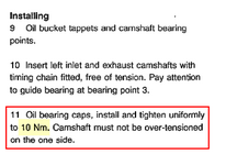
Great write-up and I will soon attempt this upgrade. Question though, this DIY states cam shaft bearing cap bolts to be re-torqued to 10 Nm. However, when I read the work shop manual it states 12 Nm. Is 10 Nm recommended for when re-using the original bolts whereas the Mercedes workshop manual assumes new bolts, new cam shafts, new cam shaft bearings etc?
 
Thanks for the link but doesn’t that say both 10 Nm and 12 Nm?
“Camshaft bearing caps 10 Nm” but “camshaft bearing cap bolts 12 Nm”.
I admit I’m confused what’s the difference as the camshaft bearing caps are secured with the bolts?
Sorry if I’m thick I just want to be sure of which is which and how much torque. From 10 to 12 Nm is still an increase of 20%

IMG_6760.jpeg
 
Ah, good catch! I was thinking there was a discrepancy somewhere but I didn't catch the 12Nm reference.

The 1993 edition TDM also shows 12Nm (this does not exist in PDF format).

In reality, the difference between 10 and 12 is nearly irrelevant - especially after factoring in torque wrench error. I'd set to 11Nm and not lose sleep over it.

:banana1:
 
Thanks guys - I was beginning to doubt whether I could do this upgrade if I couldn’t even read the workshop manual correctly. 11 Nm it is.

As for the reference to 1993 and beyond it also confuses me somewhat though it may be self explanatory once I lift off the valve covers, but what does this text mean, how do I align the caps correctly? If I tighten it all up how can the caps then align automatically to correct position? I have a M119 engine from a model year 1998 SL.

“CAUTION Since 1993 the camshaft bearing caps are no longer fixed in position with dowel sleeves but the bearing caps are centered by means of the bearing points of the camshafts when the securing bolts are tightened to specification.”
Older engines had the bearing caps numbered. I guess you could mark them yourself, if the later engine is not numbered.

1721236302485.png
 
good luck putting the valve cover gasket on and having it stay in place .I gave up after 2 attempts ,not fun cleaning garage floor when the oil gushes out!
Is this something specific to W124 vs R129? I don't recall this being an issue with the 1998 SL which is what @Benz_GT has.

Older engines had the bearing caps numbered. I guess you could mark them yourself, if the later engine is not numbered.

View attachment 196241
You can remove and replace the oiler tubes one at a time (2 clamps for each one) so identifying positions isn't really important - just place them to the side of your working area so it is obvious which goes back where.

When I removed my camshaft I just laid them all out on the bench in order from front to back of the engine.
 
Last edited:
So..instead of making a new thread..'Resurrecting this one is better i think
I am doing this job on my car..and i have done some research..and found some alaaarming comments regarding the Victor Reinz O Rings...may not be " correct"
Is there some info out there that suggests that that is the case?
Are the Victor Reinz O rings for the oilertubes,,,not excactly the same measurements as the genuine O rings from Mercedes? any info much apreaciated :)
I don't / won't use Reinz gaskets or seals for ANYTHING on my cars, never have. Generally I either go with Elring Klinger or factory. For the o-rings, they are inexpensive enough that it's best just to go factory.

Exception to this would be if an MB factory part was made by Victor Reinz. But I WILL NOT buy Reinz branded products on the aftermarket.
The issue is that they are NOT inexpensive in Norway ...they are like 18 dollars a piece..multiply that with 32..and you have quite a nice sum ,just for O rings. ... I do personally not have anything particular against Victor Reiz...but was curious to these particular o rings..if they are actually incorrect sizing..? ..With that said..i definetly agree with using factory or OEM stuff on my cars.Especially on important items such as gaskets etc.Though VR i have nothing but good experience with...
 
Last edited:
This is the part number of the MB O rings:


I used 6mm x 2mm O rings for my car and it was fine.
Thank you :) ...but i have the partsnumber. The question was more if there are actually some truth to the Victor Reinz ones beeing incorrect sizing..but i will measure the Victor ones that i got.
 
Thank you :) ...but i have the partsnumber. The question was more if there are actually some truth to the Victor Reinz ones beeing incorrect sizing..but i will measure the Victor ones that i got.
That's an insane price.

If you decide to go for MB ones, I'm happy to buy them in the UK for £1.20 each or whatever they are here and post them to you if it helps?
 
That's an insane price.

If you decide to go for MB ones, I'm happy to buy them in the UK for £1.20 each or whatever they are here and post them to you if it helps?
Yeah,its ridicilous. Thank you ..i will keep that in mind. I did measure the VR ones now..and they are 2mm,maybe 1.95....I think i will order one genuine,,and just compare i think..I will come back to you :) and to this thread later on next week :)
 
I have a genuine MB O-ring here and although it is difficult to measure, I think it is approximately:

10mm OD
6.4mm ID
1.8mm thickness

COO is Italy too!!!

As I mentioned earlier, I used 6mm ID and 2mm thickness to get a good seal on the tubes and my car runs fine.

I was happy when pressing the tubes with O-rings into position they were a good fit and the oil will pass through the tube as intended.
 
Last edited:
I have a genuine MB O-ring here and although it is difficult to measure, I think it is approximately:

10mm OD
6.4mm ID
1.8mm thickness

COO is Italy too!!!

As I mentioned earlier, I used 6mm ID and 2mm thickness to get a good seal on the tubes and my car runs fine.

I was happy when pressing the tubes with O-rings into position they were a good fit and the oil will pass through the tube as intended.
thank you.
Yes they are indeed abit tricky to measure correctly.So because of this information,.it does seem that the size of the VR ones, are at least not thinner than the genuine mb ones. So that is kinda all i need for info, to be confident in putting the VR ones in. Would be cool to go all NERD mode,and find out who supplies Mercedes with these O rings.I bought new genuine O rings for the oil cooler lines ,into the oil filter housing.And they are also green,which is not a manufacturer specific thing...but rather indicates the material type they are made of,but i always had a gut feeling that VR was /is the oe manufacturer of O rings...but i definetly might be wrong. ELring and BRUSS is also known manufactures,,,,but i feel i never see green Elring O rings...?
 
Last edited:
UPDATE
I have now ordered,and received 1 genuine Oilertube Oring from mercedes.
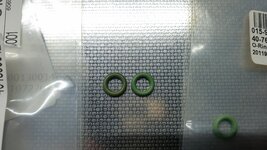
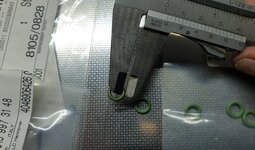
Ive done the essential feel test,but also measured it,and compared this to the Victor Reinz
They are identical in physical measure,as far as measuring carefully with a manual caliper.I dont have a digital one at hand.
I set the caliper at one setting,and let the o ring sit in between so it would not fall out on its own,and the two rings were sitting stuck ,excactly the same way.
When it comes to the feel test ,to be honest,the Victor Reinz one felt the best, a tad more plyable.
The color is as you can see ,a tad darker on the genuine one...so either it is older ,or it is a different manufacturer.
Eitherway,im super confident mounting the Victor Reinz O rings.
I hope you like the little write up 🙂
Genuine to the left, Victor Reinz to the right.
20240808_191723.jpg20240808_191730.jpg20240808_192740.jpg20240808_192840.jpg
 
Do note that the o-rings are NOT a "tolerance critical" type of application. They do not provide a super tight seal so that nothing leaks. If you look at the tubes when inserted into the cylinder heads, you can move them back and forth with your fingers pretty easily once the pressure of the cam bearings are taken off of them. I think the o-rings are only supposed to provide a loose seal. The whole are as you know is constantly bathed with motor oil when the engine is running, anyway.....

So I'm not so sure that the fitment of the o-rings is hyper important. I'm still not a fan of Reinz, though....
Hey mister.
I definetly agree that they are not "that" tolerance critical...but still they will need to be a certain size,or they will not seal as they are designed.So further...the total of the findings,sizing, material " feel" etc etc...makes them "trustable"...for me at least. When it comes to Victor Reinz i have used them in other applications for many years(In the Ford Cosworth world)....and they have never caused issues.
But these days we will have to be carefull when choosing parts for sure,and the intent with my post..was to show that when it comes to these...the VR ones are perfectly fine,and within "spec" in all areas one can know by feel and measure.Also,one last thing,, when it comes to the cost of these in some countries..like Norway for instance, It would be ridicilous to spend 18 dollars on each of these genuine ones,here in Norway,,when the VR ones are 60 dollars for all 32
 
I am going to do the oil tube replacement on my exLimited tonight, it was agreed upon the sale that I should do this. The car has been in resto mode until this summer, so it's time to choke the notorious valve ticking now when it's back on the road again.

I did two oil tubes on this car many years ago, plus on my friends E420, so I am familiar with most of the wrenching. The regular plastic tubes was used in both cases that time, but later on I collected a full set of alu.tubes for the Limited. I haven't read the entire How-To, only the first main part with all the pics and tricks. I couldn't see the torque on the bolts for the cam chain rails. Anyone have that in mind?
 
Last edited:
Just story telling..
I once removed a set of oiler tubes from the scrap yard, o-rings were fairly tight tolerance and the o-rings were soft and supple. I have no idea if they were OEM, 1st Gen OEM, 2nd Gen OEM. I would bet my depreciated bottom dollar that they were not Victor Reinz.

Wish I hadn't taken off those o-ring. I should have sold the oiler tubes, as is, with those supple o-rings. I agree, oiler tube o-rings probably don't have to be a super tight fit, but I have always been a little disappointed with the fitment of the Victor Reinz o-rings.
 
Last edited:
Back
Top