• Hi Guest !

    Welcome to the 500Eboard forum.

    Since its founding in late 2008, 500Eboard has become the leading resource on the Internet for all things related to the Mercedes-Benz 500E and E500. In recent years, we have also expanded to include the 400E and E420 models, which are directly related to the 500E/E500.

    We invite you to browse and take advantage of the information and resources here on the site. If you find helpful information, please register for full membership, and you'll find even more resources available. Feel free to ask questions, and make liberal use of the "Search" function to find answers.

    We hope you will become an active contributor to the community!

    Sincerely,
    500Eboard Management

HOW-TO: M104 / W124 Top-End Rebuild [Cylinder Head / Gasket]

gerryvz

Site Honcho
Staff member
Well, this afternoon I finally got started on my long-awaited top-end rebuild project, for my wife's 1995 E320 wagon. The symptoms that precipitated this rebuild are the following:
  • a couple of small, persistent oil leaks from the head gasket
  • a moderate leak at the front timing cover
The timing cover had been re-sealed about 5 years ago, when we first moved to Texas. It's just a fact of life that they require re-sealing from time to time, probably every 60-75K miles. The head gaskets on these cars are also prone to leakage. Generally every 100-125K miles they spring leaks and eventually require replacement.

The car currently has almost 202,000 miles on the odometer, and the engine runs excellently, with plenty of power.

This is my first time doing major rebuild work on the engine of this car. In the past I've replaced the starter, alternator, motor mounts, coil packs, neutral safety switches, and things like that, but never major mechanical surgery. Thus, as with my M117 project this will be a big learning experience for me, and I am looking forward to it.

I expect the project to take 4-6 weeks, depending on the speed at which I am able to tear down the engine, as well as the speed of the machine shop and ETA remanufacturing shop in finishing those respective jobs. The car will have all soft parts underhood basically replaced, including all rubber, plastic, hoses, vacuum lines, connectors, seals, and so forth.

So, after arranging my garage to maximize workspace at the front of the car, and moving my cars around so that the E320 will use the middle of the garage (the most versatile position as I can move my cars and motorcycle parked on either side of the car to make additional room to work, if so required), and pulling the car up on ramps, it was ready to commence the job.

Here is the results of the first day's work. It was only about 2 hours, working slowly and taking my time. Basically I removed things from the top and front of the engine, and removed the battery and engine computers to release the end of the wiring harness. With the exception of a couple of connections, the wiring harness is basically about ready to be removed from the car.

Here's the process I followed, for this first day's work.

First off, here's an "overview" look at the M104.992 engine as it appears when I began the job.
IMG_3347.JPG


As I was getting started, the mailman came, and I got a little package in the mail that made me smile ... a present from the Jack-Man (Jackasic), along with a couple of Feind Motorsports stickers. One of them promptly found its way onto the side of my toolbox....
IMG_3348.jpg


The first thing to do, was to disconnect the battery. I did this by removing the negative terminal with a curved, 13mm box-end wrench, and then wrapped the terminal in several layers of a rag and rested it against the top of the battery. This keeps it handy in case I need to briefly reconnect it to power something on the car.
IMG_3349.JPG IMG_3350.JPG


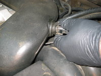
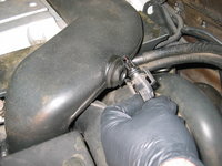
The next thing was to begin removing the intake tubing. To do this, I removed the MAF plug (rotating the knurled knob) and set it aside, and then removed the two clips that hold the air filter box to the end of the MAF.
IMG_3351.JPG IMG_3352.JPG IMG_3353.JPG


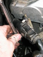
Next step is to remove the two nuts that hold the intake tube to the top of the cam cover. These are quickly dispatched, and then the intake air temperature sensor (which is shared with the M119, and is a very cheap part) is removed from its hole in the intake crossover tube. I will replace this sensor when re-installing everything.
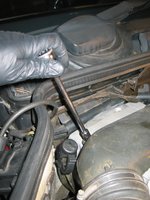
IMG_3354.jpg IMG_3355.jpg IMG_3356.JPG IMG_3357.JPG


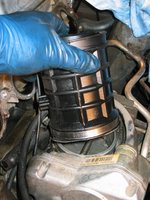
Then I loosened the MAF from the tube leading into the air filter box. The entire MAF/intake tube assembly is then swiveled a bit (loosening the ring clamp at the ETA may be necessary) and lifted upward, and off the top of the engine.
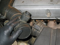
IMG_3358.JPG IMG_3359.jpg IMG_3360.jpg


This is what the engine looks like, with the intake tube off.
IMG_3361.JPG


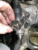
In the process of removing the intake crossover tube and MAF, I noticed that the center cladding piece (center of the inner firewall) and its insulation was all broken apart, and the plastic retaining piece for the wiring harness leads was also broken into two pieces. This is likely because of engine heat. You can see the carnage in the photos below. Add these two pieces to the tally of parts that will need to be ordered and installed upon reassembly. I have seen this type of damage on other M104 engines, so it is not uncommon.
IMG_3362.JPG IMG_3363.JPG IMG_3365.JPG


Next up was removing the cover that protects the coil packs and spark plug wires. This is held on by six 5mm Allen-head bolts, which are easily taken care of.
IMG_3366.JPG IMG_3367.JPG


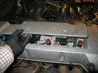
Upon opening the center compartment, the coil packs and wires are easily exposed. Here you can see the one remaining original-equipment MB coil pack, with the blue label. The other two are Bosch units (made in Slovenia) that I have replaced over the past couple of years. When I reassemble the engine, I will order a new coil pack and will install it too, and keep the blue-label pack as a reserve part.
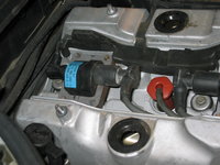
IMG_3368.JPG IMG_3369.JPG IMG_3370.JPG


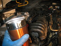
About this time, my wife brought me out a steaming-hot cup of coffee ..... which was much appreciated !!
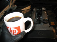
IMG_3371.JPG


Next up, time to attack the front of the motor. After removing the black plastic front cover, you can see the grit and grime covering the cam solenoid and other items in that area. Evidence of a nearby leak....
IMG_3372.JPG IMG_3373.JPG

I removed the black plastic intake air director that sits immediately behind the passenger side headlight (very similar to the one used on the E500E. Air from this director goes directly into the air filter box via this tube. Notice the partially disintegrated foam seal around the intake tube. Another "soft" part that goes onto the next parts order....
IMG_3374.JPG


One bolt later, and the mounting bracket for the air box removed, and it's time to lift out the entire air filter box....
IMG_3375.jpg IMG_3376.JPG IMG_3378.JPG


This is what the airbox area looks like, with the airbox removed.
IMG_3379.JPG
 
Last edited by a moderator:
Re: M104 / W124 Top-End Rebuild

I recognize the rag you wrapped the battery lead in.... Griots.... I bought a batch of those years ago and still have most.

I'm looking forward to this "build".

Rgds,
 
Re: M104 / W124 Top-End Rebuild
With the airbox removed, you can get a good shot of the smog pump (which I replaced a few years ago) and below that, the alternator that I very recently replaced.
IMG_3380.JPG


The next few photos are removing the cover for the wiring harness where it runs along the length of the valve cover, and loosening the channel that the wiring harness fits into.
IMG_3381.jpg IMG_3382.jpg IMG_3383.jpg IMG_3384.jpg IMG_3385.jpg


Then, it's time to remove the spark plug wires and coil packs from the center compartment.
IMG_3386.JPG IMG_3387.JPG IMG_3388.JPG IMG_3389.JPG IMG_3390.JPG


Continuing along, I started removing more of the end connections for the wiring harness at the front of the engine, and at the thermostat housing. Notice that several of the connectors were quite brittle, breaking in my fingers. Of course, they will all be replaced with brand-new connectors, having served their life of nearly 20 years and more than 200,000 miles. They are just victims of age, and engine heat.
IMG_3391.JPG IMG_3392.JPG IMG_3393.JPG IMG_3394.JPG IMG_3395.JPGIMG_3396.JPG


Next I unplugged the six wiring harness leads to the fuel injectors.
IMG_3397.jpg


After that, it was time to CAREFULLY document in my notebook the switchover valve, which is a very important component that bolts to the front of the cylinder head, behind the black plastic engine cover. The switchover valve has a number of vacuum and electrical connections, and it is important to document these CORRECTLY so that the engine runs smoothly upon reassembly. It is VERY easy to screw these connections up, particularly the vacuum lines.
IMG_3398.JPG IMG_3399.JPG IMG_3402.JPG IMG_3403.JPG


After that, to make more room at the front of the engine (I will need to turn the engine to get it to TDC eventually, and then even later on, when timing the cams, I'll need to turn it to 30 degrees ATDC), I removed the fan shroud.
IMG_3400.JPG IMG_3401.JPG


Finally, I removed the battery, because I needed to access the ends of the wiring harness where they plug into the car's computers, which are located directly behind the battery. I removed the computers and unplugged everything.
IMG_3405.JPG IMG_3406.JPG


There was a moderate amount of crap underneath the battery tray, and since it was only held in by two bolts, I decided to remove it as well. The battery tray itself was slightly rusty, but not bad given its age. Nevertheless, I will purchase some POR15 and paint it black to rust-proof it for the future. I cleaned out all of the leaves and crap with my shop-vac in short order.
IMG_3407.JPG IMG_3412.JPG IMG_3413.JPG


Before I stopped for the evening, I checked the label on the wiring harness. It was dated 2006, and I had been told that it had recently been replaced when I purchased the car in 2007, so I was happy to see confirmation that a non-biodegradeable wiring harness had been installed on the car. I could tell that it was fairly limber and flexible, which was also nice.
IMG_3408.JPG IMG_3409.JPG


Lastly I routed all of the loosened ends of the wiring harness out the inner firewall and into the engine compartment, where I will finish removing the wiring harness at a later time.
IMG_3410.JPG


That's it for the first night's work. :agree:

Cheers,
Gerry
 
Re: M104 / W124 Top-End Rebuild

Well, I had a little extra time today, before the guests arrive for Thanksgiving Dinner, so I thought I'd head out to the shop to get a few more things done.

Main things I wanted to do were to get the block and radiator drained of coolant, and to finish loosening the wiring harness. I still had a few connectors to release, attached to various things.

So, here are a few photos of what I did this afternoon.

First, I got under the car removed the lower engine cladding piece. Then, I surveyed things from below. As you can see, there's a fair amount of oil leaking. Not horrible, but a few drops a day, which doesn't make me happy.
IMG_3414.JPG IMG_3415.jpg IMG_3418.jpg


Next, it was time to drain the block. So, I located the block drain. Since it's an inline-six, and not a V-8, there is only one block drain. It was quite easy to find. You can see it in the photos below. It's a 19mm bolt, and the factory manual says you can attach a hose to it to drain it. I found that it was easier and faster just to remove it and let the block drain into a funnel I held below the drain hole, which directed the coolant into my drain pan. Seeing as I won't plan to re-use the coolant, I will recycle it when I'm done with the project. I ended up draining about 5 quarts from the block, and about 2 quarts from the radiator. This was enough.
IMG_3417.jpg IMG_3419.JPG IMG_3420.jpg IMG_3427.JPG


Here are a couple of photos of me replacing the block drain plug, after the coolant was done draining.
IMG_3423.JPG IMG_3424.jpg


About that time, my wife brought me out a nice, warm bowl of shrimp curry and rice. Yum !! Had to take a quick break to scarf that down !
IMG_3426.JPG


Next up was my continuing quest to remove the remaining connectors from the upper wiring harness. There were four or five connections remaining, including one of the fuel injectors, one of the two knock sensors on the block (the other one is impossible to get at until I remove the intake manifold), a connector at the ETA, and a couple of connectors on the passenger side inner fender well, under the black square plastic cover.
IMG_3428.JPG IMG_3429.JPG IMG_3431.JPG IMG_3432.JPG IMG_3434.jpg IMG_3435.JPG IMG_3437.JPG


With all of those connectors out of the way, only one or two remain, which I'll have to get later. Now I can gently move the very flexible and pliable wiring harness out of the way, carefully.
IMG_3430.JPG


After all that, it was time to do a little surveying work, as I look ahead. I decided to take a bit of time to investigate the "Bermuda Triangle" a bit more ... the area where the front timing cover joins up with the cylinder head and the engine block, which is very prone to leakage. Plenty of fresh oil, indicating this is probably the most active area of leakage on the engine.
IMG_3438.JPG IMG_3439.JPG IMG_3440.jpg


An early investigation also is looking like the serpentine belt is not in that good of shape (it is about 3 years old), so I will need to add a replacement serpentine belt onto my next parts order.

About this time, my wife brought out yet another steaming cup of coffee, and a gentle reminder that it was now 3:15 PM and that I needed to begin getting ready for our Thanksgiving dinner and the house-full of guests we'll be hosting in a couple of short hours.
IMG_3441.JPG


Before knocking off, I removed the plug that leads from the smog pump from its holder behind the switchover valve area. I tucked this plug down behind the smog pump and made a note of it in my notes, and took a couple of photographs, so that i remember where it goes come re-assembly time.
IMG_3442.JPG


Next up will be to remove the serpentine belt and the fan/fan clutch assembly. At that point, we'll start work on disassembly of the fuel rail / fuel system, and then disassembly/removal of the intake manifold system.

Cheers,
Gerry
 
Re: M104 / W124 Top-End Rebuild

Gerry you need to do a write up on how you do these write ups. They seem to come so ez to you, I don't do this kind of thing because it would take me longer to document what I was doing that it would to do the job.

How do you do these, IPad in the shop and enter the info right to the board as it happening ?
 
Last edited:
Re: M104 / W124 Top-End Rebuild

It's like having a Chilton's manual online with a shrimp rice bowl mixed in.
 
Re: M104 / W124 Top-End Rebuild

When my wife comes into the garage, it is usually to ask "are you done with my car yet?"

Nice work Gerry!

I grabbed a couple of hours to work on my wife's G Wagen this morning. More work to do tomorrow.
 
Re: M104 / W124 Top-End Rebuild

Gerry you need to do a write up on how you do these write ups. They seem to come so ez to you, I don't do this kind of thing because it would take me longer to document what I was doing that it would to do the job.

How do you do these, IPad in the shop and enter the info right to the board as it happening ?
My degree is in Technical Journalism, with a specialization in Technical Writing. Never used it in my career, though.

It does take quite a bit longer to document things, but it's not a huge issue. It's all part of the process these days. I've refined and evolved my technique to more of a step by step thing, rather than taking a photo every few steps.

I use a 12-year-old, 4.3-megapixel Canon PowerShot S45 digital camera, which works perfectly for this type of work. It's a compact point and shoot camera, and it takes a licking and keeps on ticking. A few years back I had to buy a non-working S45 on eBay to donate some parts to my existing camera. No iPad or other delicate equipment. The Canon camera has taken more than 23,000 photographs in its life.

Basically I take photos (I probably post about 75% of what I take), upload them, weed through them to get rid of the horrible ones or ones that aren't helpful. Then I drag the ones I intend to use into a folder on my desktop. Next, I upload the night's photos to the forum. Then, I start my write-up for the night, using the night's photos to illustrate what I did. As I write the summary, I link to the uploaded photos, and at the end all of the photos are linked, and the story is written.
 
Re: M104 / W124 Top-End Rebuild

Awesome write-up, as usual. Did you have a chance to inspect the ETA date code?

I have also found on the M104, the EGR tube that runs from the valve down a tube around the rear of the engine into the ETA is usually gunked up, and a cleaning does well. Some CEL's have been known to occur because of this symptom.
 
Re: M104 / W124 Top-End Rebuild

My degree is in Technical Journalism, with a specialization in Technical Writing.

Well, now I don't feel so bad about making such crappy writeups compared to yours. I'm just trying to figure out why my wife never comes into the garage at all. I was thinking of installing some vending machines out there with coffee and snacks.
 
Re: M104 / W124 Top-End Rebuild

Did you have a chance to inspect the ETA date code?

I have also found on the M104, the EGR tube that runs from the valve down a tube around the rear of the engine into the ETA is usually gunked up, and a cleaning does well. Some CEL's have been known to occur because of this symptom.
I have not removed the ETA as per yet, but I strongly suspect it to be original. I have a spare from a 1995 E320 wagon (with ASR, which mine also has) that I scored here at one of the wrecking yards in Houston, and I will be sending that in to be remanufactured in the very near future. So the engine will have a fresh ETA.

There are two schools of thought in cleaning/reaming the EGR tubes on the M104 engines. The conventional way, that all of the forums talk about, is to run a speedometer cable on a drill through the length of the cable and "ream" it out.

Some months ago, after years of regular CELs pointing to a clogged EGR tube, I decided to take a different route.

I removed the crossover air tube, opened the butterfly valve on the ETA, and went straight DOWN below the ETA/butterfly valve to the place below it in the intake stack, where the EGR tube re-enters the intake system. This junction where it attaches to the intake manifold just below the ETA, is where it gets gunked up with the gasoline and carbon vapors. You can run a wire straight down and then at a right angle INTO this hole, into the end of the tube, and ream it from that direction. This is more direct and gets directly to the source of the problem.

I have not had a single EGR related code (or CEL of any type, for that matter) since doing this, and it was nearly two years ago.

When I remove the EGR tube, I will examine it. I may decide to soak it and de-gunk it, or I may decide to just replace it out of hand. A new tube is upwards of $140, so it would be one of the more expensive parts purchases for this rebuild, if I so chose to replace it. I am leaning toward a thorough de-gunking through soaking.

Cheers,
Gerry
 
Re: M104 / W124 Top-End Rebuild

Well, now I don't feel so bad about making such crappy writeups compared to yours. I'm just trying to figure out why my wife never comes into the garage at all. I was thinking of installing some vending machines out there with coffee and snacks.
My wife is taking much more of an interest in this rebuild than she did with my M117, I think because it is her car that is getting open heart surgery.

Meanwhile, she's enjoying driving my E500 and has already run through more than a half-tankful of gas in the past two days !!
 
Re: M104 / W124 Top-End Rebuild

Wow.

Now here gentlemen, is a man who loves his wife! Show of hands: How many here would let THEIR wives drive THEIR 036s? OK, now how many would let their wives drive their 036s Un-chaperoned? (Dave, I don't think you count because the 036 your wife drives is actually HER 036, right? But you do get big points for buying it for her though! You did buy it, right?)

Not to mention how hard Uncle is working on her car!

Uncle Gerry, please feel free to show this post to your wife. Does she appreciate just how loved and privileged she is? (My guess is she does, as evidenced by how thoughtfully she is attending to your gastrointestinal needs.)

I think this has been discussed before, but what is a "safe" date code break point for the wiring harnesses to be sure that it is a non-biodegradable one? Does this break point also apply to M119 harnesses?

I may have missed it, but what will be the status of the belt tensioner, timing chain, and rails? Have they ever been addressed? Will they be on this project?

Regards,
Eric
 
Last edited:
Re: M104 / W124 Top-End Rebuild

A fail-safe date code for any M104 or M119 harness would be 1999-2000 or later.

I have not gotten to the belt tensioner, timing chain, rails, idler pulley, etc. yet. I do have new rails, belt tensioner and chain on the purchase list, though. The idler pulley was replaced about 3 years ago so I will inspect it when I remove it. The serpentine belt, from what I can see, has cracks in its underside and so is ready for replacement. That belt is about 3.5 years old.

The chains on the M104 are fairly short and don't have the wear issues like the V-8 chains do on the M117 and M119; that said the car has over 200K miles on it, so I have to assume it's the original chain, and thus will need to be replaced.

So the short answer to your questions is YES ... all of those parts will be replaced. When doing a job like this, I don't mess around.

When I did my M117 a few years ago, I didn't replace the fuel injectors (which were about double the miles past their service life) and ended up replacing them about a year later; it would have been 100% incremental labor to have replaced them. In this case the injectors on my M104 are fine (they don't wear out like the CIS-E injectors do) but I will look to replace any and everything that is a "wear" part while I have things apart.

You guys are getting ahead of me with the parts questions !! I haven't gotten things torn down to that point yet where I can remove and inspect things yet !! All in due time.....all in due time.....

Cheers,
Gerry


P.S. Since my college days, I have tried to always keep the following words close to my heart, which were authored by our President Calvin Coolidge:

Nothing in the world can take the place of persistence.
Talent will not; nothing is more common than unsuccessful men with talent.
Genius will not; unrewarded genius is almost a proverb.
Education will not; the world is full of educated derelicts.
Persistence and determination alone are omnipotent.
The slogan Press On! has solved and always will solve the problems of the human race.
 
Re: M104 / W124 Top-End Rebuild

Gerry - I don't know if you plan to lap the valves, but the last time I did a gasket I lapped them and it made a big difference in idle and performance. I also sent the injectors off to http://www.deatschwerks.com/ to be cleaned and flow tested. It takes maybe a week, but they come back looking brand new with new o-rings and a table that shows performance at 3 or 4 flow rates after cleaning.

-Mike
 
Re: M104 / W124 Top-End Rebuild

Hi Mike,

I do plan to bring the head into the best Houston Benz machine shop (Scroggins Machine, which did my M117 heads) to be fully inspected, pressure tested, cleaned and have the valve stem seals replaced. If the valves/seats need to be done, they will certainly be authorized to do this. I will leave it up to them as to what their inspection and tests recommend be done. Scroggins are real pros and know Benz engines very very well. http://www.scrogginsmachine.com/

Thanks for the tip on the injectors. I have a spare set of M104 injectors and it may well be a good idea to send them in. I'll noodle on that.

Cheers,
Gerry
 
Re: M104 / W124 Top-End Rebuild

You guys are getting ahead of me with the parts questions !! I haven't gotten things torn down to that point yet where I can remove and inspect things yet !! All in due time.....all in due time.....
Gerry, I won’t fire any questions but can i comment on your preferred workshop attire ?

The “country check shirt” is the focus here guys, not the rusty battery tray !! :D

proxy.php


Nothing in the world can take the place of persistence.
Talent will not; nothing is more common than unsuccessful men with talent.
Genius will not; unrewarded genius is almost a proverb.
Education will not; the world is full of educated derelicts.
Persistence and determination alone are omnipotent.
The slogan Press On! has solved and always will solve the problems of the human race.


Yep! And as Winston Churchill once said, “ Keep buggering on”


Amazing write up so far, btw.
 
Re: M104 / W124 Top-End Rebuild

I agree bing....odd choice for working on the car.....probably was on the top of the Goodwill bin where Gerry gets most of his clothes :gerry:
 
Re: M104 / W124 Top-End Rebuild

P.S. Since my college days, I have tried to always keep the following words close to my heart, which were authored by our President Calvin Coolidge:

Nothing in the world can take the place of persistence.
Talent will not; nothing is more common than unsuccessful men with talent.
Genius will not; unrewarded genius is almost a proverb.
Education will not; the world is full of educated derelicts.
Persistence and determination alone are omnipotent.
The slogan Press On! has solved and always will solve the problems of the human race.

I used to have a copy of that posted on my bedroom door when I was still in my teens. It wasn't properly credited though, so I never knew where it originated from. Thanks for the closure, some thirty plus years later! Now you now why I felt so convicted the other day when you threw Yoda's words at me. That plus I was compelled to "live" what I'm trying to teach my kids!

Regards,
Eric
 
Re: M104 / W124 Top-End Rebuild

Today was a long day ... I worked for about 5 hours out in the shop. The weather was nice and mild, as we're finally coming out of the cold snap we've been having for the past few days (highs in the 50s, lows in the low 30s). Today it was up into the mid 60s, which is very comfortable temperature for working in the shop.

Basically today, I did the following:

  • Removed the fan and fan clutch assembly
  • Removed the serpentine belt
  • Removed the coolant crossover pipe across the front of the motor
  • Started removing the fuel rail
  • Removed both exhaust manifolds
  • Partially removed the smog pump, to swivel it out of the way to access the chain tensioner

So, here's how the day went per description, with photographs.

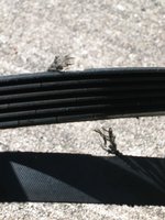
First, I removed the serpentine belt. Luckily my wife's car, being a 1995 model, has the later-style belt tensioner, which is easier to deal with than the first variety used on the M104. Earlier, I had noticed what looked to be cracks in the belt, before getting it off the car. Once it was off ... let's just say that it was in clear need of replacement. The belt, FYI, was 3.5 years old. Another part for the parts order....
IMG_3443.JPG IMG_3444.JPG IMG_3446.JPG IMG_3464.jpg IMG_3468.JPG


I struggled with the fan pulley for the better part of an hour. I had the factory tool to hold it in place, but after much struggling, and close examination, finally determined that the end of the tool was too long, and too large in diameter for the M104 pulley I was dealing with. So, I walked over to my shop grinder and ground off about 0.75 cm from the end of the tool, and tapered it a bit so that it would fit into the holes in the pulley easier. Once I did this, I was done in about 5 minutes and could loosen the fan bolt. I finished the fan bolt off with my handy palm-ratchet, which provided some low profile clearance against the radiator.
IMG_3448.jpg IMG_3450.JPG IMG_3452.JPG IMG_3453.JPG IMG_3454.JPG IMG_3456.JPG IMG_3458.jpg IMG_3459.JPG


A side note -- now that I've drained the radiator (except for the transmission coolant circuit) I think I am going to just remove it from the car for best clearance and access to the front of the motor when reassembling things. Honestly, in the end it will be easier.

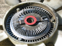
Here are a couple of views of the fan clutch, after being removed from the car. The clutch had been replaced about two years ago. I smelled and spotted some funky liquid on the back-side of the sealed bearing. I hope that is not fan clutch juice !!
IMG_3460.JPG IMG_3461.JPG IMG_3462.JPG


Here's a view of the front of the engine, taken from above, with the fan and fan clutch removed.
IMG_3469.jpg


Next up, it was time to remove the coolant crossover pipe/hose that runs across the front of the block, directly behind the fan and fan clutch assembly. This was done by removing a hose connection, as well as a bolt that held the end of the pipe to the water pump/thermostat housing, and a hold-down Allen bolt that held the pipe to the front of the block. This was a fairly easy operation.
IMG_3470.JPG IMG_3471.jpg IMG_3472.JPG IMG_3473.JPG IMG_3474.JPG


Here, I'm lifting the loosened crossover pipe out of the engine compartment. Notice the smashed/well worn-in O-ring on the end of the pipe. Another "soft" part that goes on the next parts order.
IMG_3475.JPG IMG_3476.JPG IMG_3477.JPG


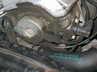
Here's a good photo of the front of the engine, at the bottom of the front timing cover, with the crossover coolant pipe removed. You get a good shot of the "Bermuda Triangle" area where the head, block and timing cover meet, and where the majority of the oil leak has been coming from. The timing chain tensioner is in the lower left of the photo (looks like a bolt-head). That will be removed (and replaced with a new unit) at a later time.
IMG_3478.JPG IMG_3479.JPG


Next up is the smog pump ... removing the top bolt, so that it can be swiveled downward and out of the way, for future access to the timing chain tensioner. This was a very easy operation to loosen and then remove the top bolt.
IMG_3480.jpg IMG_3481.JPG


Moving forward, it was time to begin to loosen the fuel rail, which is the preceding step to removing the intake manifold itself (and the remaining two connections holding the wiring harness to the car). The fuel rail is held by five 7mm hex bolts, and they were extremely tight!! I removed three of the five bolts, and busted one of my "wobbly" hex-head sockets in the process. Not happy about that, so I decided to take a breather from finishing that step and move on to the exhaust manifolds.

Before starting on the fuel rail, however, I relieved the pressure from the fuel system by loosening the gas cap, which gave a "whoosh" as the pressure let out.
IMG_3483.JPG IMG_3484.JPG


Then I started removing the fuel rail hold-down Allen bolts.
IMG_3482.JPG IMG_3485.JPG IMG_3486.jpg


Then, I loosened the connections at the fuel supply and return lines, using two wrenches as a counter-hold.
IMG_3487.jpg IMG_3488.jpg IMG_3489.JPG IMG_3491.JPG IMG_3492.jpg IMG_3493.JPG
 
Re: M104 / W124 Top-End Rebuild

Yep! And as Winston Churchill once said, “ Keep buggering on”

And as an old Navy man he would certainly know about buggering...

or as the Pogues title album describes it --- "Rum, Sodomy and the Lash"

Ron
Churchill was giving a speech when two backbenchers whispered among themselves "they say the old man is losing it." Churchill, without missing a beat, replied "they say he's deaf too."
 
Re: M104 / W124 Top-End Rebuild

I bent the fuel hoses upward and tucked them behind some wiring on the underside of the hood, so they wouldn't leak gasoline. It was then that I noticed the following MAJOR SAFETY HAZARD in one of the fuel lines. There were three or four of these. So, of course, the car will be receiving new fuel lines as part of the parts order.
IMG_3494.JPG IMG_3495.JPG


I felt thankful and lucky with that one, seeing as that bulging fuel line could have let go at any time, starting an underhood fire. I wonder how many fires have been caused by failed fuel lines like that.

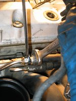
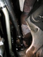
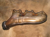
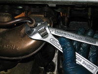
Next up, I decided to attack the exhaust manifolds. This job was harder than it looked, simply because a number of the bolts were fairly difficult to reach, and had to be loosened with a box-end wrench and pure elbow grease. I had previously soaked them for a hour or two with PB Blaster, which I am sure helped immensely. Also I had to remove the four bolts that connected each of the exhaust manifolds to the exhaust flanges leading to the catalytic converters. These, of course, were rusted into place, but with some PB Blaster and persistence, I finally got them too.
IMG_3496.JPG IMG_3497.JPG IMG_3498.JPG IMG_3499.JPG IMG_3500.jpg IMG_3501.JPG


First manifold coming off of the head....and a view of the exhaust ports....
IMG_3502.JPG IMG_3503.JPG IMG_3504.JPG


And the EGR valve coming off of the second manifold....
IMG_3505.JPG


And the second manifold coming out of the car....
IMG_3506.JPG


The two manifolds together...
IMG_3507.JPG


And a nice view of where they used to live.
IMG_3508.JPG


Last step for the day ... removing the metal exhaust manifold gaskets, and placing everything side by side on the shop floor.
IMG_3510.JPG IMG_3511.JPG IMG_3512.JPG

Decided at that point to call it a wrap for the day. Hadn't eaten anything, and my son came out and wanted to order pizza. I was hungry for pizza too....
 
Re: M104 / W124 Top-End Rebuild

As I was putting my parts order together last night, I jotted down the part numbers for the upper and lower wiring harnesses for the late six-cylinder 124s. Wow -- MSRP on the upper harness is now up to $1,250 (parts.com almost $900!!) , and the MSRP on the lower harness is pushing $150. I've known they were more expensive than the harnesses on the .036 (MSRP $870 for a late 036 upper harness), but wow, the price has gone up on the six-cylinder harness by about 50% in the past 5 years.
 
Re: M104 / W124 Top-End Rebuild

:update:

Today, I only worked about three hours on the car, but they were quite productive hours. I had a couple of mysteries to solve, left over from the past couple of nights.

These mysteries:

  • Loosening and removing the last two bolts that held the fuel rail to the cylinder head
  • Finding a way to loosen and remove the intake manifold, which was held on by four additional hex-head bolts, all of which were at very difficult angles

Having a night to to ponder and noodle on things was a very helpful, and allowed me to approach these tasks with a fresh perspective.

The two bolts that held the fuel rail were particularly troublesome (there were five bolts total, three of which I had removed with not too much difficulty). One of them was at the very front of the cylinder head, and the other was at the very rear of the cylinder head and down, so at an awkward angle.

The intake manifold bolts could only be removed once the fuel rail was removed, because they were otherwise inaccessible. So first things had to come first.

Also, I did not want to remove the valve cover until both the exhaust and intake manifolds were removed from the car. The reason for this was that I wanted to be able to work on a "bare" engine block and head, unencumbered by peripheral parts and systems. Less complexity and clutter always streamlines the process.

I did the first of the three hours after getting home from taking my daughter to a classmate's birthday party, and then I had to go and pick her up again, so after returning home around 6 PM Central time, I performed the remaining two hours of work. I also spent 10-15 minutes surveying the work I'd done today, and plotting out my next moves. I'll discuss that at the end of the day's posts here.

So, let's get into what I got done today...... :pc1:

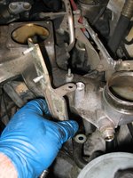
The first job was to remove the lifting lug from the front of the cylinder head, which also has a clip attached that holds a connector that leads to the smog pump (I'd previously removed the connector). That was just a couple of Allen bolts, quickly dispatched of course.
IMG_3514.JPG IMG_3515.jpg IMG_3516.JPG


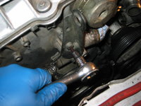
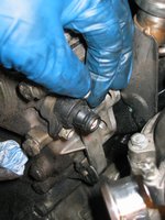
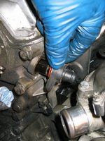
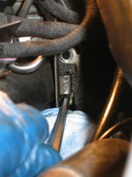
The second "housekeeping" job was to remove the camshaft position sensor, which is located on the front of the cylinder head, on the driver's side edge. Again, just a couple of bolts and easy removal.
IMG_3517.jpg IMG_3518.jpg


Next on the agenda, was to tackle those two, pesky fuel rail Allen bolts, located at opposite ends of the fuel rail. To remove the front-most one, I had to remove the entire water pump assembly to give me enough room to get a bite on the fuel rail bolt. After removing the water pump, it was only seconds before that second-to-last fuel rail bolt was removed.

But first, I had to remove the four Allen bolts that held the fuel pump onto the cylinder head. Three of these bolts were fairly easy, but the fourth one is UNDERNEATH the pump, and you don't really have a good line of sight to it, so you sort of have to "feel" the Allen socket into the head of the bolt. Luckily, I did this without too much problem, but I had to use a convoluted assembly of sockets, wobbly and extensions to remove it.

I also had to remove all of the coolant hoses attached to the water pump housing. I'll clean up the housing later on, and I already have a new thermostat and o-ring on order. The last photo below is removing the water pump housing from the car.
IMG_3519.jpg IMG_3520.JPG IMG_3521.JPG


Here's a view of what the area looks like where the water pump sits.....without the water pump in place.
IMG_3522.JPG


And here I am, removing that next-to-last fuel rail bolt at the front of the cylinder head. It's quite easy when you don't have a water pump and thermostat housing in the way !!
IMG_3523.JPG


Next up, had to tackle the LAST fuel rail bolt, at the very back of the engine. To do this one, I had to remove the oil filter housing cover, and the oil filter itself. I plugged up the oil filter housing with a lint-free towel, and then draped another lint-free towel across the top of the housing so as to keep grit and grime out of the oil filter housing. I will do an oil change when this is all done, for several reasons, but it was a prudent move to keep crud out of the oil.

I had to use a very long extension, but again it was fairly easy with the rounded plastic oil filter housing cap out of the way. I could get a MUCH better angle to get a "bite" on the Allen bolt.
IMG_3524.jpg IMG_3525.JPG


The next step was to remove all six of the clips that attached the fuel rail to each injector, and kept things snug. I did this quickly with a simple, flat-blade screwdriver.
IMG_3527.JPG IMG_3526.JPG

From there, the fuel rail (with injectors attached) just pulled straight up and out of the engine compartment. I set it aside and dumped the small amount of fuel in the rail onto my driveway, where it quickly evaporated. I set the fuel rail and injectors aside to air out, knowing that I would remove the injectors from the fuel rail later in the evening.

Then it was time for the remaining "to do" task left over from the previous night ... removing the four bolts that secured the plastic top-half of the intake manifold to the cylinder head. These Allen-head bolts were torqued VERY HARD to the head, and probably baked on with lots of heat generated over nearly 20 years and 200,000+ miles on the road. Two of these bolts I was able to get a decent angle on with a wobbly socket attached to my 6mm Allen socket, but the remaining two were VERY difficult. I used PB Blaster and let that soak in for a few minutes before trying to get them.
IMG_3528.JPG IMG_3530.jpg IMG_3532.JPG

I finally got the third one, but the last one proved to be very difficult. So difficult, in fact, that I rounded the inside of the Allen head with my Allen key, leaving me in a bit of a temporary bind until I figured out what to do.
IMG_3533.JPG


Finally, after trying Vise-Grips on the head of the bolt, I was able to get it manually with my Knipex adjustable pliers. Wow, talk about dodging a bullet. Then I was able to remove it (once loosened) with my ball-head Allen key.
IMG_3534.JPG IMG_3535.JPG


Here's what the head of that Allen bolt looked like.....that's some serious carnage....guess I'll be re-ordering a new set of four of those bolts, just to be on the safe side.
IMG_3537.JPG


After that, I loosened the two large diameter short rubber hoses that connect the upper and lower halves of the intake manifold together, and also removed the vacuum connection that goes from the intake runners to the transmission modulator (on the driver's side of the transmission).
IMG_3538.JPG IMG_3539.jpg


Then, I was able to manually separate the halves of the intake manifold by wiggling it apart, and I could reach down and release one of the two remaining connections from the wiring harness that I was unable to reach previously .... the connector that led to the second of the two knock sensors embedded in the outside of the block.

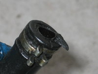
At this point, I made a crucial mistake, and I should have known better. I pulled the manifold straight up and out, and didn't disconnect the two vacuum hoses that attach directly to the underside of the manifold. Unfortunately, both of the hoses had become fossilized (never seen rubber hoses this hard ... EVER) and fused to the plastic connectors that they clamped to. I am talking FUSED....as in inseparable. Impossible to tell where the plastic ended and the rubber hose began. So I completely cracked one of the fittings off, and broke the end off the other one. Stupid mistake. I will have to tap two new fittings into the plastic housing. Not the end of the world, and I have plenty of time (weeks) until I remount the intake manifold top half, but I am PISSED at myself for doing this and not knowing better. UGH.

Here are a few photos of the removal of the top half of the intake, and the carnage that I described above per the two vacuum hoses.
IMG_3540.JPG IMG_3541.JPG IMG_3542.JPG


Here's what the surface of the top half of the intake manifold looks like where it mates to the cylinder head. The green seals will be shortly removed, and replaced (new ones are on order as part of the head gasket kit).
IMG_3543.JPG


And, here's a view of the intake side of the engine, showing the lower half of the intake manifold, ETA and cylinder head.
IMG_3544.jpg


Next item to remove was the rubber boot that attaches to the top of the ETA. I had just replaced this boot about a month ago, so I know it is fine and totally un-fossilized. It will be re-used.
IMG_3545.jpg


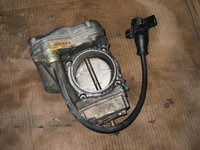
With all that done, the ETA was finally exposed. And, a bit of sleuthing confirmed what I had suspected all along -- the ETA was the original unit, per the date-code on it of November, 1994.
IMG_3547.JPG IMG_3548.JPG


It was then time to move on to removing the gaskets from the intake manifold. This was quickly accomplished using my very small "pick" tool. I also removed the remaining metal spring clamp from the fossilized hose. I will replace this crappy spring clamp design with a proper clamp upon reassembly and re-installation.
IMG_3549.JPG IMG_3550.jpg


Continued in next post....
 
Re: M104 / W124 Top-End Rebuild

At this point, I was deciding to begin to wind down for the night, and to do some relatively light "housekeeping" tasks.

So, first off I sat down on the garage floor and proceeded to separate the injectors from the fuel rail. I bagged each of the injectors and marked which cylinder they had come from. I have decided to send the injectors in to have them sonically cleaned and restored, and flow tested before and after.

This is all just part of "doing the rebuild right" instead of slap-dashing things back together. Hopefully the injectors, with 200K miles on them, are in good shape and can be reconditioned to provide some increase in power and efficiency through better atomisation of the fuel.

Here you see me using a flat-blade screwdriver to gently coax each injector out of the fuel rail.
IMG_3552.JPG IMG_3553.jpg


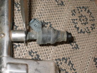
And then, you see my small "pick" tool removing each of the fuel injector o-rings. These will be replaced and are on order.
IMG_3554.JPG IMG_3555.JPG


The last job for the night, was to remove the ETA from its resting spot on the lower part of the intake manifold. This was accomplished by removing the four 5mm Allen bolts that held the ETA to the manifold. They weren't very tight, so this was a rather easy job.
IMG_3556.jpg


Then, I removed the two 10mm nuts that held the plastic ETA connector in a static position. Then I flipped up the security flap that securely holds the two halves of the ETA plug together, and then pulled the two halves of the ETA electrical connection apart. This only took a couple of minutes.
IMG_3557.jpg IMG_3558.jpg IMG_3559.jpg IMG_3563.jpg


I next removed the spring and ball-socket connector that connects the throttle linkage to the ETA. After doing that, the ETA was able to be lifted out of the car, and placed on the garage floor for further inspection.
IMG_3560.JPG IMG_3561.JPG IMG_3562.jpg IMG_3564.JPG IMG_3565.JPG


Here's a view of the top of the lower intake manifold, with the ETA removed.
IMG_3566.JPG


My last task for the night was to examine one of the fossilized hoses coming down from the top half of the intake manifold, and to check its part number. Both of these fossilized hoses are on my first parts order, so they will arrive soon. I can't explain enough how fossilized these hoses were. They were actually plastic, not rubber. Hard to believe they once WERE rubber.
IMG_3567.JPG


And that does it for the night.

For Sunday's tasks, I will disassemble the remainder of the intake manifold and remove it and associated items from the engine. Then I will delve into removing the valve cover, and disassembling the cylinder head itself by removing the camshafts. The head will be prepped for delivery to the machine shop (I hope to deliver it to the machine shop by Thursday or Friday of next week).

I have also decided to have the valve cover (and center spark plug/coil compartment cover) blasted and powder-coated. I have the time, and it won't be that expensive to have this done. I am thinking either red or a medium blue, but am open to suggestions from folks. A red valve cover would give the engine compartment some visual pop, eh?

Give me your thoughts on this.....

Cheers,
Gerry
 
Re: M104 / W124 Top-End Rebuild

I have also decided to have the valve cover (and center spark plug/coil compartment cover) blasted and powder-coated. I have the time, and it won't be that expensive to have this done. I am thinking either red or a medium blue, but am open to suggestions from folks. A red valve cover would give the engine compartment some visual pop, eh?
Give me your thoughts on this.....
Cheers,
Gerry

FYI:
http://www.ebay.de/itm/171178783246?ssPageName=STRK:MEWAX:IT&_trksid=p3984.m1438.l2649

I'm going to consider color coordinating it with the body... Malachite.

I wouldn't blast it with anything other than soda or walnut shells.
You don't want glass or AO getting embedded in the alloy only to escape into the oiling system after repeated heating/cooling cycles.

Kind Regards,

Ron
 
Re: M104 / W124 Top-End Rebuild

I'm going to consider color coordinating it with the body... Malachite.
Ordinarily, I would consider doing this. But an Arctic or Polar White engine cover would very readily show every speck of underhood dust, grit and grime.
 
Re: M104 / W124 Top-End Rebuild

Satin black valve cover with the coil cover in contrasting red or silver.
 
Re: M104 / W124 Top-End Rebuild

I wouldn't blast it with anything other than soda or walnut shells.
You don't want glass or AO getting embedded in the alloy only to escape into the oiling system after repeated heating/cooling cycles.
I think Ron is correct. Safe blasting media would be a good idea. Either red or blue would be pretty kewl! But pretty much any color would provide some "pop"!

:duff:
 
Re: M104 / W124 Top-End Rebuild

Gerry:
Try different colors. Just get a couple of rattle cans and spray the cover to see what it looks like.
What looks good on the floor may not look good under the hood or on the engine.
Then strip it for the final painting.

Ron
 
Re: M104 / W124 Top-End Rebuild

:update:

Today was a fairly quiet Sunday, but with a very mild 70F temperature outside. This allowed me to wear shorts and a t-shirt out in the garage, which made for some pleasant wrenching. I only worked for about two hours in the garage, taking my time. Mainly today was a "clean-up" day to disconnect the remaining items attached to the bottom half of the intake manifold, and to remove the intake manifold itself. I also loosened all of the bolt that hold the valve cover onto the top of the cylinder head, but have not yet removed the valve cover.

I also took some time to carefully update my records. As with my M117 top-end rebuild, I made a separate list of all of the vacuum connections on the engine, by location and color of vac line, and starting and ending point. This allows for accurate reconnection of all vacuum lines when reassembling things. I will replace all vacuum lines and rubber connectors, just as I did with the M117 rebuild, which will ensure that the engine is ready for another 15+ years and 200,000 miles of trouble-free running. The last thing I want is for a vacuum connection or line to be broken a year from now, necessitating a difficult replacement process. It's just much easier to do that work now, and not have to worry about it down the road.

Overall, I am finding that the vacuum lines and rubber connections on the E320 are MUCH less fragile/brittle than those on my 560SEC, which is a mere six years older than the E320. I think this could be a function of a bit better airflow in and around the engine, perhaps keeping things a bit cooler and "cooking" the soft parts less. Nevertheless, there have been a number of soft parts (such as the two rubber hoses going downward from the top half of the intake manifold) that have indeed been, what I call, "crispy critters."

In any case, here is what I did today, illustrated both verbally and photographically.

First order of business was to continue my work on the intake manifold's bottom (aluminum) portion.

I took inventory of the vacuum connections I could see....
  • the white one leading to the valve on the driver's side fender
  • the small diameter black one from the plastic intake runner to the transmission modulator
  • the large diameter black one from the ETA to the OTHER valve on the driver's side fender
IMG_3568.jpg IMG_3577.JPG IMG_3578.JPG IMG_3569.jpg IMG_3570.jpg


The next item that needed to be removed was the vacuum line that goes from the intake manifold to the brake booster. There is a check valve in the middle of this line (you can see it in the last photo above). I was very leery of this line, because it cracked in half on my M117 rebuild at the check valve, and this was quite an expensive line on the 560SEC !! Luckily it seemed to be fairly robust, and although the check valve showed some flaking on the outside, the line seemed to have integrity. Nevertheless, I'll check the price on it to see whether I should throw it onto my next parts order. It is likely that I will do this, as a matter of course.
IMG_3571.JPG IMG_3572.JPG


I needed to remove the ETA connection cable that was routed near the intake manifold, so carefully tried to prise up the plastic connector that held it down. Unfortunately I cracked it (these get brittle quite easily due to engine heat). Which honestly was fine, because I've already got a supply of these on my latest parts order. I ordered 5-6 in anticipation of just this event happening. Yes .... when I say I'm going to replace all of the "soft parts" underhood ... it extends to these plastic pieces too. No zip ties for GVZ.....
IMG_3573.JPG IMG_3574.JPG IMG_3575.JPG IMG_3576.JPG


This switch on the driver's side fenderwell is what the white vacuum line shown above, connects to. This switch is the manifold absolute pressure (MAP) sensor switch, and is part of the car's emissions system.
IMG_3579.JPG


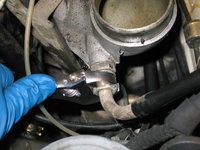
Next off, it was time to remove the second "fossilized" hose that came down from the bottom of the top plastic part of the intake manifold. This vacuum line goes into the base of a metal housing just below where the water pump mounts up. I used a flat-blade screwdriver to carefully coax the hose off the metal flange. The other end of this hose, as shown, has the plastic nipple that once extended down from the bottom of the plastic intake manifold. Now, these pieces are fused together.
IMG_3580.JPG IMG_3581.JPG IMG_3584.JPG


Here is a shot of the two "fossilized" hoses together .. showing their part numbers. Both are inexpensive hoses (under $10 USD) and are on my first parts order from MB.
IMG_3583.JPG


The next job was to remove the bracket, which mounts to the lower half of the intake manifold via a 10mm and 13mm bolt, that holds the ETA cable connection. This was quickly dispatched from the side (10mm), and underneath (13mm).
IMG_3585.jpg IMG_3586.JPG IMG_3587.jpg


Then, it was time to remove the "notorious" EGR tube, where it bolts into the lower part of the intake manifold. Two 10mm bolts, and a 5mm Allen bolt that held it to the flange of the oil filter. There is still one Allen bolt that holds the tube to the rear of the cylinder head, but it is hard to reach and I will get it at a later point in time. I also removed the gasket for this tube, and have a new one on order. Of course, later on when I remove the tube from the car, I will examine it closely and make the determination about whether to clean it up/out, or to replace it. Since it's a $140 tube and it's metal (i.e. not a "soft" part, I will likely soak and clean it with carb cleaner and re-use it.
IMG_3588.jpg IMG_3589.jpg IMG_3590.jpg IMG_3591.jpg IMG_3592.JPG IMG_3593.jpg


Here's a photo of that rear-most Allen head bolt that mounts the EGR tube to the rear of the cylinder head. I'll get this one later on....
IMG_3594.jpg


Here are a couple of photos of the end of the EGR tube, where it fits into the intake manifold. You can see the gummy caramel-colored "goodness" of the carbony-stuff that hardens inside the end of this tube, and causes lots of nice Check Engine Lights for thousands of owners around the US....
IMG_3595.JPG IMG_3596.jpg


It was then time to remove the throttle linkage and Bowden cable combination, which bolts to the lower part of the intake manifold by three 10mm bolts. This was also dispatched with relative ease, and after removing the linkage, I disconnected the end of the throttle cable from the linkage, and tied the whole assembly up and out of the way above the engine, so I had more room to work on things and clean the area.
IMG_3597.jpg IMG_3598.JPG IMG_3600.jpg IMG_3601.jpg IMG_3604.jpg


About this time, my wife brought me out a nice cup of black coffee.... so had to stop and enjoy a few sips of that before "buggering onward" ....:cheers1:
IMG_3599.JPG


continued in next post....
 
Re: M104 / W124 Top-End Rebuild

A few more shots from the process of removing and buttoning up the throttle & Bowden cable linkage....
IMG_3605.JPG IMG_3606.jpg


I removed a last vacuum line from the lower part of the intake manifold, in the rear. This is a yellow and white striped line, that leads up to the vacuum check valves near the fuse panel, and goes into the passenger compartment from there.
IMG_3608.jpg


It was then time to begin removing the grand prize of the day ... the lower part of the intake manifold from the block. Four 13mm bolts was all it took .. very easy and drama-free process, thankfully.
IMG_3607.JPG IMG_3609.JPG IMG_3610.JPG


One more thing to get out of the way ... the engine oil dipstick. This was a bit of a surprise to me ... it just presses into the engine block and is sealed with a simple o-ring (which I'll replace). It is held to the intake manifold by a top clamp via a flange in the upper part of the tube, which I'd removed previously. So to remove the dipstick, I simply and carefully pulled the tube straight out of the block, and then inserted a piece of lint-free towel into the hole. I'll pull the towel out later on when I'm ready to re-assemble things, but in the meantime will clean up the dipstick tube.
IMG_3613.jpg


I also moved the aforementioned black vacuum line out of the way (leading from the intake manifold to the transmission modulator on the driver's side) and released (carefully, and without breaking it this time) the pronged plastic clip. Piece of cake....
IMG_3611.jpg IMG_3612.JPG


Funnily enough, I came across a red wasp's mud nest (either partially completed, or broken apart) on the motor mount arm.
We have a lot of these wasps in the Houston area, and they constantly infest my garage area during the summer and build their mud nests all over the place. It's great sport to blast them with RAID or other spray, and smash their nests with a screwdriver when I find one.
IMG_3614.JPG


Lastly, and the last job of the day, was to begin removing all of the bolts that hold the valve cover to the top of the cylinder head. There are three rows -- one row on each side, and a few bolts in the middle. All 10mm jobs, of course. I'll leave the conclusion of this operation for the next installation of this saga.
IMG_3616.jpg


Cheers,
Gerry
 
Re: M104 / W124 Top-End Rebuild

Tonight was a quiet night in the shop, and I only spent about 15 minutes out there.

Specifically, I did two tasks.

1) I removed the remaining 5mm Allen bolt that holds the EGR tube to the rear corner on the driver's side of the cylinder head. It's in a tough spot to get to, because of its location directly below one of the heater hoses. I was able to CAREFULLY get it loosened a bit with an allen key, a quarter-turn at a time, until I got frustrated. Eventually, I just went into my tool chest and got out the "wobbly" 5mm Allen socket that one uses to install and remove the M119 valve cover rear bolts. Worked a charm with an 8-inch extension on my 1/4" ratchet. Got it out in about a minute after that.

2) I finished loosening the bolts holding on the valve cover, and pulled the cover off the head briefly so that I could inspect things on the top of the cylinder head. Things looked great -- no build up or sludge whatsoever (a by-product of me changing my dino oil every 2,000 miles) and no perceptible wear on any of the cam lobes.

I replaced the cover and will work on things a bit more in the coming nights. I am waiting on my first order from parts.com to arrive, which contains the special XZN (12-point) socket that is required to remove the cylinder head bolts. Tomorrow night I'll turn the engine at the crank to TDC position for Cylinder 1, which I'll need to do to mark the cams and measure chain stretch (if any).

In the meantime, I have a few daytime things to do:

a) Contact Bobby Scroggins at Scroggins Machine and let him know I'll be bringing in the cylinder head next Monday to be worked on, and ask him how long I'll be looking at and what my ballpark costs will be. I'll also bring in the lower portion of the intake manifold and have them dunk it and clean it up.

b) Contact the paint shop for cleaning of the valve cover and spark plug compartment cover, and have them painted. I think I'm going to go with a red color for maximum visual pop (I promise NOT to call the engine a Brabus though)

c) Package and send off the injectors to Oklahoma for testing and refurbishment

d) Finalize what I'm going to do with the ETA. I was in contact with Beckmann today. They want about $750 + a $100 core deposit for a rebuilt ETA. I did not yet hear back from BBA Reman (I expect they will be cheaper) but if I don't hear back from them, then I'll just go with Beckmann which is fine. I will slit open the wiring bundle and let folks here have a peek at what the original wiring looks like in the ETA cable bundle. Beckmann has proper rebuilt units in stock, and ships out with about a 2-day delivery. Not much choice on this one, and they do good work (Jono seal of approval).

That's about all for now....

Cheers,
Gerry
 
Re: M104 / W124 Top-End Rebuild

:update:

Here's an update on my progress for the day.

First of all, I found a decent powder coating shop that is between my home, and my office. And, they are open at 7 AM, so I can leave the house at 0630 and still get into the office by 0730 after stopping to drop off my valve cover pieces. I am going to have them paint it red. Still considering whether to have the center piece (covering the plugs/coil packs) painted black or red. Probably will just go with red all over. I stopped by on my way home tonight and met with the owner.

Question - is the cover aluminium, or magnesium? I am tending toward alumimium, but wanted to make sure, as it will matter to the powder coating guys.

They said it will take about a week to accomplish, and cost about $125 for everything. I will take it in about the same time I do the head to the machinist, so that they are being taken care of at the same time.

Next up, I did a little side project tonight. I opened up the ETA to check on the condition of the wiring, given that it has 201,000 miles on it and is 18 years old. Below is the saga of (and results from) the process.

Read and enjoy !

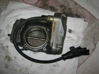
Here's the ETA, as removed from the car. I have not cleaned it up. I already mentioned that it is the original unit, dated November 1994, so there is a 100% certainty that the wiring inside is "biodegradable" wiring.
IMG_3617.JPG


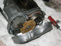
Here's a view of the end of the ETA, which has the cover that I'm going to remove. This covers up the gears and motors that transfer the electrical signals from the EGAS computer in the CAN box, into the ETA, into mechanical motion.
IMG_3618.JPG


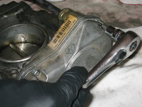
And here's a close-up of the four Torx screws that hold the cover onto the body of the ETA. These are special "secure" Torx screws, which have an extra prong in the middle of the bit. This means that a regular Torx bit will not work in this type of screw, so you have to get a separate set of these secure Torx bits. Luckily, I had purchased a set at a tool store several months ago, so I was prepared for this potential complication....
IMG_3620.JPG IMG_3621.JPG IMG_3622.jpg


Removing the secure Torx screws from the housing with the special socket, mounted to a spare 3/8" ratchet.
IMG_3623.JPG IMG_3624.JPG IMG_3625.JPG


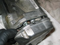
After the four screws were removed, I used a small, slim flat-blade screwdriver to force the two halves of the housing apart. It didn't take much effort....
IMG_3626.JPG IMG_3627.JPG IMG_3628.JPG


And then, to get a better view of the wiring coming into the ETA from the plug, you have to use a regular T-10 Torx screwdriver to remove the two screws that are holding the small circuit board to the inside of the ETA housing....
IMG_3631.JPG


And, here are a few views of what I found. From what I could see, while the wires were certainly degraded, I only saw one or two blatantly bare wires. Although, there could well have been some bad/bare wires inside the cable leading to the ETA.
IMG_3632.jpg IMG_3633.JPG IMG_3635.JPG IMG_3636.JPG IMG_3638.JPG


And, then I buttoned things back together just the way I found them. You can see the flaked wiring insulation on the towel I had been resting below the ETA during disassembly. Wow.
IMG_3639.JPG


Hope you found this little update interesting. Tomorrow I will package up and send off the six fuel injectors to the fuel injector shop in Oklahoma for flow testing and refurbishment.

Cheers,
Gerry
 
Re: M104 / W124 Top-End Rebuild

Wow , Gerry ! 200kmiles on this ETA , guess you can't complain . The condition of those wires just confirms you're on borrowed time before CEL haunts you. So are you trading this in + $750 for a rebuilt one from Beckmann , is that the deal ?


Sent while on the road using Tapatalk
 
Re: M104 / W124 Top-End Rebuild

I am hooked on this like I was watching Breaking Bad. Gerry, you are not allowed to take a night off or I will suffer from withdrawals...
 
Re: M104 / W124 Top-End Rebuild

Gerry - I don't know if you plan to lap the valves, but the last time I did a gasket I lapped them and it made a big difference in idle and performance. I also sent the injectors off to http://www.deatschwerks.com/ to be cleaned and flow tested. It takes maybe a week, but they come back looking brand new with new o-rings and a table that shows performance at 3 or 4 flow rates after cleaning.

-Mike
Mike,

Thanks for this recommendation. I checked it out and decided to take your advice. Sending the injectors off to Oklahoma today at lunch. I really look forward to learning what they found, and what they did to improve/rebuild the injectors. I wonder if it will make a difference in the mileage/performance. Unlike CIS-E injectors, I am just thankful that our M104 and M119 injectors are rebuildable.

Again -- thanks for the info.

Cheers,
Gerry
 
Re: M104 / W124 Top-End Rebuild

Wow , Gerry ! 200kmiles on this ETA , guess you can't complain . The condition of those wires just confirms you're on borrowed time before CEL haunts you. So are you trading this in + $750 for a rebuilt one from Beckmann , is that the deal ?
I'm thinking now I may go another route and source a used unit with low mileage for about half the price. We'll see what shakes out, but I won't hesitate to go Beckmann if I have to. If I can save a few hundred bones, that will fund one of my parts orders ... or the valve cover bling + injector refirb.
 
Re: M104 / W124 Top-End Rebuild

Well, my parts boxes are rolling in from MBUSA's warehouses (two received Thursday and Friday from MB Naperville and MBUSA's Fort Worth warehouse), and three more are slated to arrive on Monday from MBUSA's Fontana, CA, Robbinsville, NJ and Carol Stream, IL parts depots. That will comprise my first parts order, and the next one will go out on Tuesday next week.

Tasks to be completed on Saturday and Sunday will be:

  • removal of the camshafts and further disassembly of the cylinder heads
  • examination of the valvetrain parts for any wear and tear
  • removal of the front timing cover
  • cleaning of the block
  • preparation of the valve covers to go to the powder coater's on Monday
  • preparation for removal of the cylinder head from the block on Tuesday and Wednesday nights
  • preparation for the replacement of the timing chain
  • replacement of all cracked plastic electrical connectors underhood with new units from MB

I also received an order of aftermarket parts from AutohausAZ.com, which included the following:
  • Contitech serpentine belt
  • Bosch coil pack
  • IWIS timing chain
  • Behr thermostat and gasket
  • Six Bosch F8DC4 spark plugs

Interestingly, it appears that MB has superseded the hex-head bolt for the fan clutch to a star (Torx) head bolt. I had ordered a new fan clutch bolt as a precaution and insurance for the future, so that there is no chance of stripping this difficult-to-access bolt. The bolt I received, after ordering the EPC's bolt part number, had a Torx head but is otherwise an identical size. I wonder if this is a supercession, or just a replacement. MB has a special stubby hex socket for the stock fan clutch bolt, so I guess I may have to remove the radiator to make enough room to get a true ratchet/Torx socket down in there. SIGH.

I am looking forward to my Christmas Holidays, starting on Friday night, December 13, which will be a nice, 2.5 week vacation.

Cheers,
Gerry
 
Re: M104 / W124 Top-End Rebuild

I would curious to see what the fuel injector rebuilder does to the injectors because there aren't many moving parts. I'm guessing they are just going to run carb cleaner through them and replace the screens and o-rings. I have found that if the injector clicks when voyage is applied the injector is working. Most good fuels have cleaners mixed in so they rarely clog unless they've been siting in the junk yard for a few years. I have always had good results with the typical rebuild kits. There are also a few good sources for cleaned and rebuilt injectors. I've used injector-rehab.com and RJM injection technologies for rebuild kits. The owner of RJM was having some health issues and may have closed shop. He has a great website on fuel injection http://oldfuelinjection.com. All be it based in Ford, he has great info on EFI principles. I've done a couple EFI conversions and his website was quite valuable.
 
Re: M104 / W124 Top-End Rebuild

I am having them do before and after flow tests, so we should be able to see what the scoop is and how much of a difference is made. The will ultrasonically clean them and yes, replace the "consumable" parts in them. IMHO injectors should be serviced every 100,000 miles. I strongly considered buying a rebuild kit and doing the work myself, but I don't have the flow equipment and I'm dying to see what the flow characteristics of these injectors are after 201K miles.... Of course I will post/share the reports here. I only run Chevron Super (lots of Techron) and Shell V-Power gas in my car, so I am sure that it gets plenty of good cleaning through the gasoline that I use.

One of my future projects is going to rebuild a spare M117 CIS-E fuel distributor that I have. That's a very delicate operation. With the CIS-E injectors, you just throw them out every 80-100K miles -- they are not rebuildable or really clean-able. Unfortunately the price has recently doubled on them so they are around $40-50 each compared to the $20-25 that they were until a couple of years ago. But that's still better than the $200-250 each for the M119 LH injectors..... or the M104 Motronic injectors.
 
Re: M104 / W124 Top-End Rebuild

This has been a very interesting thread. It's amazing how much stuff you have to remove to get to the pesky head. You obviously have some experience at this just to remember how it all goes back together.

Could you post a picture of the car. I'm an MB newbie so I don't even know what vehicle this is.

:oldman:

It's a 1995 W124 wagon. White over black leather with ASR, orthopedic seats, seat heaters, and so forth.
 
Re: M104 / W124 Top-End Rebuild

Is ASR unusual for this car? Again, please excuse my naivety.
 
Re: M104 / W124 Top-End Rebuild

Gerry- you should remove the two rubber breathers on the top of the valve cover (for the intake crossover tube) prior to sending off to powder coat or paint. I left them on and they pretty much fossilized after being powder coated. They were a royal pain to take off then. I just remembered this and wanted to save you from a potential pitfall.
 
Back
Top