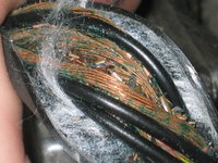
• Hi Guest !

    Welcome to the 500Eboard forum.

    Since its founding in late 2008, 500Eboard has become the leading resource on the Internet for all things related to the Mercedes-Benz 500E and E500. In recent years, we have also expanded to include the 400E and E420 models, which are directly related to the 500E/E500.

    We invite you to browse and take advantage of the information and resources here on the site. If you find helpful information, please register for full membership, and you'll find even more resources available. Feel free to ask questions, and make liberal use of the "Search" function to find answers.

    We hope you will become an active contributor to the community!

    Sincerely,
    500Eboard Management

HOW-TO: M104 / W124 Top-End Rebuild [Cylinder Head / Gasket]

Re: M104 / W124 Top-End Rebuild

This is a really neat thread Gerry.
I have a 94' wagon that has 230k on the clock. I have done most of the "easy" maintenance through the years and paid to have both engine and transmission "resealed" at the 150k mark.
So far, no leaks or issues that I know about. The ETA was replaced with a Beckmann somewhere around 180k.
I am getting a little braver each time I do a job, but would NEVER have attempted anything if it were not for you and others on this site.
My biggest accomplishment, so far, are the metal oil tube job on the 93' 500E. For a novice, like me, it was scary, but with your "how to" guide, it was a success!
I don't know if I'll ever do anything this ambitious with my wagon,I but am enjoying learning about all of these steps. You have a knack at presenting things that even a novice can emulate. Thanks for taking the time to explain everything. Every other "how to" book or publication I read assumes I actually know something about turning wrenches. I DO NOT. So, your guidance is all I have to do certain jobs.
I especially appreciate your listing of EVERYTHING needed to do a job. You list part numbers, tools needed, AND how to use those tools. Before this site, I was completely in the dark.
Just keep writing assuming that your audience is like me (a novice), and I'll keep changing fluids and filters and hope for the best with my wagon.
I wonder how long I can keep her going before I have to do something like this?
 
Re: M104 / W124 Top-End Rebuild

This is a great read as usual Gerry! I was indifferent at first, but now I look forward to my daily dose of "top end rebuild"
Sh%t, I could read your how-to on rebuilding a toilet! :flush:
 
Re: M104 / W124 Top-End Rebuild

Gerry- you should remove the two rubber breathers on the top of the valve cover (for the intake crossover tube) prior to sending off to powder coat or paint. I left them on and they pretty much fossilized after being powder coated. They were a royal pain to take off then. I just remembered this and wanted to save you from a potential pitfall.

I will. Actually I have two new ones on order. They are not cheap! When I say I'm going to replace all soft parts underhood I try to extend it to everything !!


Sent from my iPad using Tapatalk HD
 
Re: M104 / W124 Top-End Rebuild

:update:

Today I spent a little time at the wrecking yard, and dropped by the mechanic shop. I saw G-Man's car in there up on the lift ... it's getting ready for a transmission rebuild. But mainly I stopped by to drop off my set of old, plastic M119 cam oiler tubes, which they are going to use on a car (to replace a popped one), and to secure the use of the owner's timing chain link removal/installation tool, so that I don't have to go and buy one myself -- they are around $700-800 so not cheap !! It is ready for me when I need it, as it's not a tool that they use every day.

Anyway, today I spent about 1 hour and 15 minutes out in the shop, and did a few tasks in preparation for removing the head, which I am probably going to do on Monday or Tuesday night this coming week. Before doing that, I have to remove the front cover, the cam sprockets, and camshafts, from the cylinder head. Here's what I did during the 1.25 hours I worked today. Tomorrow I'll put some more time into things to remove the cams, and on Monday morning on the way to work, I'll bring the valve cover and the battery tray into the powder coater to be painted.

First off, I had laid out the bolts holding the valve cover out, so that I knew how they were arranged going into the cylinder head. The metal/rubber washers will be replaced as part of the reassembly process - they have been ordered from MB. They are a very important part that prevents oil seepage/leakage at the valve cover bolts.
IMG_3640.JPG


And here are a couple of views, lifting the valve cover off of the top of the cylinder head.
IMG_3641.jpg IMG_3642.jpg


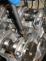
Here are the first good views I had of the cylinder head. Everything looks nice and clean, and the cam lobes look good, for having more than 200,000 miles on them....
IMG_3643.jpg IMG_3644.JPG IMG_3645.JPG


After doing that, I removed the three 5mm Allen bolts that hold the cam advance solenoid to the front of the timing cover. These were very easy to remove, albeit the lower one (closest to the oil leaks) was pretty encrusted with grime. But after removing it, as you see below, 10 seconds with some brake cleaner cleaned it up quite nicely. Good stuff, that brake cleaner. It did not appear that the cam solenoid was leaking oil. I have the special MB anaerobic sealant, so I will clean off the two sealing surfaces and re-seal it during the reassembly process. It will be almost identical to the process I did back in May when I re-sealed the cam solenoids on my E500.
IMG_3651.JPG IMG_3652.JPG IMG_3653.JPG IMG_3654.JPG IMG_3655.JPG IMG_3656.JPG IMG_3657.JPG IMG_3658.JPG

The next job was to remove the front cover from the engine. As you probably have seen, the front cover was leaking at the lower corners, so the area around it was very grimy and gritty. Spraying the area liberally with Chlorinated Brake Cleaner (I bought four more cans of it today when I was out running errands) helped illuminate the six bolts that hold the front timing cover to the front of the cylinder head.

Though these six bolts were torqued quite tightly, they came out fairly easily. It appears they may have had some sort of sealant attached to them, as they were all quite "flaky" as I extracted them from the front cover. Interesting.
IMG_3646.JPG IMG_3647.JPG IMG_3648.JPG IMG_3649.jpg IMG_3659.JPG IMG_3660.JPG


The lower left bolt, on the passenger side of the head, was an interesting one. It was not only encrusted with grime, being immediately above the Bermuda Triangle leakage area, but it cannot be fully extracted from the cover while on the car, because of the pulley in front of it. So it is loosened and then removed from the car while still inserted into the timing cover. I'll have to remember to re-install it that way, too, or I'll have to re-do the installation of the timing cover -- a job that I will ONLY want to do once. Some liberal use of brake cleaner cleaned up the area enough so that I could get my 13mm curved, box-end wrench on it, and it came loose without too much difficulty.
IMG_3661.JPG IMG_3662.JPG


Here's the layout of the timing cover bolts, as removed from the car. The space in the middle is for the aforementioned lower left bolt.
IMG_3663.JPG


Of course, the front timing cover was "welded" to the front of the cylinder head on account of being in intimate contact for a number of years, and probably about 65,000 miles, so I used a small block of wood and a hammer to carefully "coax" it free of the head. Here are a couple of photos of the removal of the front cover, immediately after breaking it free of the head.
IMG_3664.JPG IMG_3665.jpg IMG_3666.JPG


Then, I removed the top timing chain guide rail, which is a small, triangular piece. It was quite dark in color, but looked good, and it wasn't too deeply scored. Still, given the color, it was certainly time to replace it. Hard to say if it was the original, probably not, but still probably close to 10 years old if a day.
IMG_3667.JPG IMG_3668.JPG IMG_3669.JPG


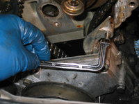
Here are some close-up shots of the timing cover seal area, and the "Bermuda Triangle" -- which is the origination point for probably the majority of oil leaks on M104 engines. This is with the timing cover seal still in place.
IMG_3670.jpg IMG_3671.JPG IMG_3672.JPG IMG_3673.JPG IMG_3674.JPG IMG_3675.JPG


Here, I am removing the seal.
IMG_3676.JPG IMG_3677.JPG


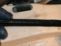
A close inspection of the underside of the seal shows that it is a factory MB part, with the Bruss manufacturer name on it.
IMG_3678.JPG


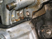
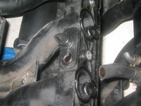
And, here's an intimate view of the Bermuda Triangle, on the leaky passenger side, with the seal removed.
IMG_3681.JPG


To be continued in next post ....
 
Re: M104 / W124 Top-End Rebuild

The next step was to turn the engine to Top Dead Center, which is marked by the "0|T" on the damper. You have to use a 27mm deep socket, and a little bit of elbow grease, to get things PERFECTLY lined up.
IMG_3682.JPG IMG_3683.JPG IMG_3685.JPG


After setting things to TDC, you insert a dowel or other object into the holes in the back-side of the cam sprockets. If things are properly lined up, the dowels are basically supposed to be resting on the top of the cylinder head. When I did this, the exhaust cam was fine and lined up well, but you can see that the intake cam is a couple or three degrees off. This is an indication of timing chain stretch, and an additional impetus to replace the timing chain to bring the engine back into correct sync.
IMG_3687.JPG IMG_3686.JPG


From there, it was time to put the engine to bed for the night, so I covered the exposed cylinder head and cams with sheets made of fresh shop rags.
IMG_3688.jpg


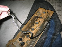
As a last task, I took a look at the freshly removed valve cover. I removed the gasket from the edge of the cover as well as one of the spark plug gaskets that had stuck to the bottom of the valve cover. Six new spark plug gaskets will come with the valve cover replacement kit from MB.
IMG_3689.JPG IMG_3690.JPG IMG_3691.JPG IMG_3692.JPG

Cheers,
Gerry
 
Re: M104 / W124 Top-End Rebuild

Wow, are you sure you got it lined up? Those duplex chains are pretty robust and with only 200k miles should have minimal wear. Mine at 300k did not need replacement.
 
Re: M104 / W124 Top-End Rebuild

Wow, are you sure you got it lined up? Those duplex chains are pretty robust and with only 200k miles should have minimal wear. Mine at 300k did not need replacement.
You can see for yourself, the timing mark is right on the line between the 0 and the T. I lined it up 3-4 times (it's a pain to rotate the engine even once, and you have to rotate it twice to line it up again) and every time it came out same. Visual evidence is with the allen key about 2 cm off of the top of the cylinder head. Believe me, I was surprised too. My M117 (with a much longer chain) was off by less than that !!

It doesn't really matter, as it's getting a new IWIS chain anyway.....so everything will be reset timing-wise when the new chain is rolled in.
 
Re: M104 / W124 Top-End Rebuild

It almost looks like the sprocket is a tooth off. Has the head been off before? Any chance someone put it back together wrong?
 
Re: M104 / W124 Top-End Rebuild

It almost looks like the sprocket is a tooth off. Has the head been off before? Any chance someone put it back together wrong?
I thought as much too, when I saw that. Believe me, I triple-checked everything. The holes in the sprockets won't line up anywhere near the heads in the off-cycle of the crank, so it is definitely in the right part of the cam timing/crank stroke.

There are no other timing pointer marks anywhere near the flywheel down there ... I don't know if that one I show looks like yours. Mine doesn't look like other M104s I've seen photos of, though.

I am told that the head has been off before, yes. I don't think it's as far as a tooth off though. I'm going to do a bit more research tonight before I tear into things more. But the cams are going to come off tomorrow.
 
Re: M104 / W124 Top-End Rebuild

:update:

Today I went back to the wrecking yard, and was able to score a nice, used spare plastic portion of the M104 intake manifold, as well as a very nice spare E320 MAF and some other various miscellaneous parts and relays, including 126 and late 124 OVP relay spares. I also got a spare fuel tank vent valve that mount onto the driver's side fender (applicable for both the E320 and the E500) that is fairly expensive. I left a couple of spare E320 EGAS and HFM engine computers in the cars, as I already have spares. Also got another spare temp display (I have 2-3 spares already), just for karma.

After I got home, I spent several hours researching the puzzle over why my intake camshaft is so far out of alignment. Either the chain is stretched, or it is (as Glen suggested) a tooth off. However, if it was a tooth off, I believe it would bend the valves (interference motor) so that would continue to steer me toward the theory of the chain having stretched. In any case, it is a puzzler, and I did not want to proceed substantially until I'd looked more into this mystery.

I will remove the camshafts from the car on Monday night, and then the cylinder head on Tuesday night, and bring it into the machine shop (along with the lower part of the intake manifold, for cleaning) on Wednesday morning. The valve cover parts and the battery tray are going into the powder coater on my way to work tomorrow (Monday).

Now, a bit more about the plastic, upper portion of the intake manifold. As you may recall, there are two vacuum hoses that attach to two nipples on the bottom of the plastic portion of the intake manifold. One of these hoses is a short hose, and goes to the ETA. The other, longer hose goes down to the power steering pump/water pump area. These are vacuum lines, and their connection to the bottom of the plastic intake manifold is side-by-side, to a plastic cap.

When I removed the spare intake manifold from the car in the wrecking yard today, I was very careful to bring a hacksaw blade and cut these two hoses off, so that they did not pull on the nipples attached to the intake manifold, and break off the nipples as happened to my original. These hoses on the wrecked car, too, were completely fossilized. For comparison, I have already received the spare hoses, and while they are firm, thick rubber, they are somewhat pliable in nature, which is helpful knowledge.

Anyway, what I found was something that I has suspected previously (with my original intake manifold) but had not confirmed. This is that both of the nipples are molded into a separate, rectangular plastic piece that is glued/bonded to the bottom of the intake manifold. It is this rectangular piece that gets broken, not the thick plastic intake manifold itself. I used a screwdriver today, after removing the intake manifold from the car, and found that the rectangular piece CAN be separated from the rest of the intake manifold. I was able to do this (since the hoses were cut short) and then see that the intake manifold has a small, sealed compartment molded into it, which this rectangular piece fits into. It in effect becomes a sealed compartment.

So, what I'm going to have to do, is VERY carefully take a Dremel cutting tool and remove the fossilized ends of the two hoses that I cut on the spare car. Then, I will bond/glue the rectangular piece to my original intake manifold, after removing the broken original rectangular piece from it. Then I can attach the two new short & long vacuum hoses to the rectangular piece, and will be on my way. I guess I will use JB Weld to attach the intact rectangular piece to the original manifold.

Interestingly, when I removed the rectangular piece from the spare manifold at the wrecking yard, the small compartment that it covered up was TOTALLY gummed over with crap, very much like the EGR tube where it goes into the intake manifold. I expect my original manifold is similarly gummed up, so I'll have to be sure to clean it out before I JB Weld the new rectangular piece to it.

Bottom line, I was grateful to get a new, intact rectangular piece for the intake manifold. This will save me A LOT of time and effort over having to source and then tap new fittings into the original, broken rectangular plastic piece. It was worth the one hour of labor at the wrecking yard to score the intake manifold !!

I've tried to illustrate this situation with photos, so hopefully this all makes sense.

Back to the camshaft timing issue .... since I'll be replacing the timing chain with a new one, it will give me the opportunity to completely reset and adjust the camshaft position vis a vis the crankshaft. So, in the long run, this will be a totally moot point. But it is a mystery, and one that made me exceedingly cautious, because it was both unexpected and potentially troublesome. I wonder, when the engine is reassembled and the cams and crank are back in proper time, if my wife and I will notice a difference in the power of the engine. Only time will tell, I guess.....

Cheers,
Gerry


Here are some photos that hopefully illustrate my dialogue, above.

First, here are the "new" replacement MB rubber short & long hoses that attach to the bottom of the plastic portion of the intake manifold.
IMG_3695.JPG


Then, a few close-up shots of the rectangular piece that the two hoses attach to, as removed from the intake manifold. The cut pieces of fossilized hose are still attached. You can see in the last photo how gummed-up the inside of the rectangular piece is ... the nipple on the right side is totally blocked !!
IMG_3696.JPG IMG_3697.JPG IMG_3698.JPG IMG_3699.JPG


And here are a couple of photos of the bottom of the intake manifold that I got today at the wrecking yard. You can see the hole in the bottom of the manifold where the rectangular piece fits...
IMG_3700.JPG IMG_3701.JPG


Here is a close-up of the rectangular piece, and how it fits into the intake manifold. I have already cleaned out about 95% of the crap that was clogging that passage inside the spare intake manifold.
IMG_3702.jpg IMG_3703.JPG


Here's a close-up view of the broken piece, in the original intake manifold. The old rubber hoses literally fossilized and bonded with the nipples on the rectangular piece.
IMG_3704.JPG IMG_3706.JPG


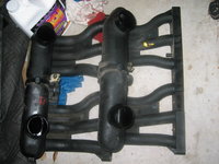
The two intake manifolds, side by side, showing the two rectangular pieces and how they fit into the manifold.
IMG_3705.JPG IMG_3707.JPG


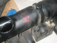
One thing I just discovered tonight ... the "original" intake manifold appears also to perhaps be sourced from a wrecking yard, lending credence to the fact that the head has already been off the car. Evidently the prior mechanic also busted the intake manifold, as evidenced by the red markings on the bottom of the manifold.
IMG_3708.JPG IMG_3709.JPG


A very positive side benefit of snagging the spare manifold today, was the addition of the "resonance valve," which is screwed into the top of the intake manifold. This valve is EXTREMELY expensive (retails for around $450, and is somewhere around $350 via parts.com) and it's nice to have a spare one. This valve is an air-flow control valve and partially controls idle characteristics on the M104.
IMG_3710.JPG
proxy.php
 
Re: M104 / W124 Top-End Rebuild

Gerry, it's possible that one cam could be one tooth off, and not bend valves. It depends which direction it's off, and if it's 1 tooth or multiple teeth. I've seen an M119 that had three of the four cams 1 tooth off (retarded direction, not advanced) and the engine ran for years like that with zero damage. Definitely is a mystery though!

:detective:
A common mechanic's mistake on the M104 is, upon reassembly, lining things up correctly with the markings made on the chain and both sprockets, but NOT rotating the intake cam adjuster to the "retard" position (clockwise to its stop, as you are looking at the engine from the front of the car). The engine will run fine this way, although it will throw cam-adjustment related codes. Mine has never done this, so I'm assuming it was assembled correctly, but it's another reason that the cam timing can be off.

You and Glen may well be right about being one tooth off! Again it will be a moot point as I'll be rolling in a new chain, and part of that process is adjusting the cam timing in relation to the crank just after the chain is rolled in. I'm going to replace the chain when the head is off the car, as it's less complicated (better access & visuals) to do, and then when the head is re-installed line everything up again.....and triple-check it per the factory procedure. Thankfully the factory manual is pretty good with regard to all of these cam timing-related operations.

When I remove the intake cam, I am not going to bother disassembling the advance/retard adjuster mechanism and removing the sprocket from the cam ... no need to, and you don't have to. You do have to remove the sprocket from the exhaust cam, but that's only three bolts :)

Cheers,
Gerry
 
Re: M104 / W124 Top-End Rebuild

Gerry:

Instead of gluing the rectangular piece back on perhaps plastic welding should be considered.

Kind Regards,

Ron
 
Re: M104 / W124 Top-End Rebuild

Gerry, is it possible that when the head was last off that someone removed the cam sprocket(s) and reinstalled incorrectly? I've never pulled off a cam sprocket so I don't know if it is idiot proof. Great writeups so far, even though I may never work on a six.
 
Re: M104 / W124 Top-End Rebuild

Gerry, is it possible that when the head was last off that someone removed the cam sprocket(s) and reinstalled incorrectly? I've never pulled off a cam sprocket so I don't know if it is idiot proof. Great writeups so far, even though I may never work on a six.

Possibly. It could also be off if the head was skimmed in the past. I'll learn mire from the machine shop when they examine it.


Sent from my iPad using Tapatalk HD
 
Re: M104 / W124 Top-End Rebuild

Gerry,

Nice score at the junk yard. At some point, do you mind showing us how you catalogue the parts that you remove? I am interested in knowing how you store the parts and keep them organized for re-assembly. Just a couple of photos would be great.

Good going on the tear-down.
 
M104 / W124 Top-End Rebuild

For storing my MB spare parts inventory:

Normally I just bag small parts in spare MB parts bags and use a Sharpie to write on the bag/label what the part is and what car(a) it is for. I store parts in bins depending on the type and size (for example computers and relays go into one type of bin).

Then I maintain a spreadsheet with my "inventory" that includes MB part number, quantity, notes about the part (age, source, car from, etc) if applicable, and other notes as to whether it is known-good, new, questionable, broken or possibly a donator for a core.

That's about it.

As far as the parts from the rebuild ... Same thing. I bag them in small & large Ziplock bags & write on the bag what it is, and any info as to where it goes if there are multiple sizes of bolt in the bag.

Also I try to write torque value on the bag for reassembly (if spec'd) and if replacement of any contents is needed (for example a stripped Allen head).

Parts are stored near the car in large plastic storage bins with the lids off.

All steps are documented in a notebook as to every operation performed as it is done and then of course you see my photographic documentation ... 90% of the photos are taken for forum illustration purposes, only 10% are for reference purposes. I use about 75% of the photos that I take in my nightly installments here.

Does this help?


Sent from my iPhone using Tapatalk
 
Re: M104 / W124 Top-End Rebuild

That helps. I hear of various tricks, like pieces of cardboard with bolts punched through in the appropriate patterns for re-assembly. What you say makes sense. Not sure why I always worry about forgetting the exact re-assembly process. While I have never done a project as large as a re-build, I have never had an issue with re-assembly before.

I am fascinated by your thoroughness and ability to document the process. As a reader, I feel that I could rip into an M104 today and have success.
 
Re: M104 / W124 Top-End Rebuild

This was how I did it on one project (OM603, sorry, Gerry). I forgot to take photos when I did the M119's.

proxy.php
 
Re: M104 / W124 Top-End Rebuild

On my rebuilds I have placed blots for each various assemblies in zip lock bags labeled with a sharpie. Front cover bolts seem always be different lengths so I lay them out according to there location. It's nice if you have nice big work bench like Dave's where they can stay until use. I don't have that luxury.

In a pinch for bolts I have found that Ace Hardware has a great selection of grade 8 bolts in standard and metric sizes. They have been very valuable on my hot rod builds where originality isn't important. Ace has the best off the shelve assortment I have ever found. Way better than Home Depot or Lowes.
 
Re: M104 / W124 Top-End Rebuild

There are times that I have use cardboard with holes punched in for maintaining places for specific parts. Check my M117 Top End Rebuild thread in the C126 section and you will see where I did this with the hydraulic valve parts.

I draw plenty of diagrams in my notes (for example vacuum routing diagrams with color & destinations of vac lines) and also I will draw out diagrams for bolts or routing wires (I did this for the spark plug & coil pack wires on this build).

Also, for parts like the cam bearings, which must be reassembled in the same place as they were originally installed, I label the bags with the correct number (ie cylinder) and then draw a diagram in my notes that corresponds with each number/place.


Sent from my iPhone using Tapatalk
 
Re: M104 / W124 Top-End Rebuild

All good advice. Thanks fellas. It would be nice to have a large workbench. My next house (in 20 years?!) will have priority on the garage/work space. A small two car garage doesn't cut it for me!
 
Re: M104 / W124 Top-End Rebuild

There are times that I have use cardboard with holes punched in for maintaining places for specific parts. Check my M117 Top End Rebuild thread in the C126 section and you will see where I did this with the hydraulic valve parts.
Here's a photo of the box I used holes punched in for the hydraulic lifters, on my M117 rebuild 3.5 years (and 32,000+ miles) ago. I had a corresponding diagram drawn inside of my notebook as a fail-safe mechanism.

I also use my notebook for time tracking (start and stop times for each work session). For this build, I am also tracking the number of cups of coffee and 60-oz styrofoam cups of soda consumed. I did not do this for the M117 rebuild.

http://www.500eboard.com/forums/showthread.php?564-560SEC-top-end-rebuild&p=2050&viewfull=1#post2050


proxy.php
 
Re: M104 / W124 Top-End Rebuild

This morning, on the way to work, I had my two new Conti tires mounted and Hunter RoadForce balanced, and installed on the rear of my 560SEC. Then, I dropped the valve cover (confirmed to be magnesium), center piece and the battery tray off at the powder coater to be blasted/cleaned and then powder coated. The valve cover is going to be painted "Red Baron Red" and the battery tray will be matte black. They said they are not busy, so it will be ready by the end of this week. Total cost for all parts will be $175.

Cheers,
Gerry
 
Re: M104 / W124 Top-End Rebuild

When ever I tackle a medium to large sized job, I use a large piece of card board. On one side I even right down the steps. I even draw diagrams sometimes. If need be, I use plastic baggies, labeled. I learned the carboard trick from "Wheeler Dealers"
 
Re: M104 / W124 Top-End Rebuild

:update:

Well, it was like Christmas today when I came home from work.....I had three boxes waiting for me from parts.com, which was the balance of my first parts order.

So, I resolved to get going tonight and to get the camshafts off the car, in preparation for tomorrow's removal of the cylinder head. Headed out to the shop about 8:15 PM, and figured I'd get about an hour or two worth of work in for the night. In reality, it was about 45 minutes.

Here's how things went.....

First, I woke the M104 up from its nap from the past couple of days. Then I double-checked the timing, where I'd left things before at Top Dead Center (TDC).
IMG_3711.jpg IMG_3715.JPG

It was then time to put the engine in the 30 degrees BELOW TDC mark, so I turned the motor a couple of revolutions to get things into the right spot. This position, at 30 degrees BTDC, allows both camshafts to turn without the valves contacting the tops of the pistons. This is an important step, as you'll see in a few minutes.....
IMG_3718.JPG


The next job was to remove the chain tensioner. This is not a huge job, but I'm planning to order a new one on my second parts order anyway, so I wasn't too stressed about things. This is a critical part, so I figured after 200,000 miles, $90 spent on a new tensioner wouldn't be a bad thing. At least they're MUCH cheaper than the tensioners used on the M117 engines, which I believe are pushing $300 these days....

The first step to remove the tensioner, is to use a 10mm Allen socket to loosen the inside of the tensioner by about 1 turn.
IMG_3719.JPG


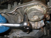
Then, you use a 27mm socket to remove the outer housing from the cylinder head. This is the same size socket used to turn the crankshaft to get the engine in to time, but in this case the "deep" 27mm socket was too long, so I had to revert to my "regular" 27mm socket to provide enough room for the ratchet to access the tensioner without having to totally remove the smog pump from the motor.
IMG_3723.JPG IMG_3725.JPG IMG_3726.JPG IMG_3727.JPG


After carefully bagging and tagging the tensioner, I marked the cam sprockets and chain with black paint. Then, it was time to remove the exhaust cam sprocket. This was just three easy Torx T40 bolts, removed with a ratchet.
IMG_3728.jpg

Here are a couple of shots of the exhaust cam sprocket coming off....
IMG_3729.JPG IMG_3730.JPG


A cursory examination of the cam sprocket teeth showed no abnormal wear, which is a good thing. All those 2,000 mile oil changes evidently help with SOMETHING....
IMG_3731.JPG


Then, it was time to remove the chain from the INTAKE sprocket, just by lifting it off.
IMG_3732.JPG


Next, I kept the top of the chain taut by using a bungee cord, suspended from an overhead object, to keep a little upward pressure on it.
IMG_3733.JPG


After that, I removed the five rubber spark plug sealing rings that keep oil from going into the spark plug wells. These sealing rings are part of the valve cover gasket kit, but I bagged and tagged them anyway for reference.
IMG_3734.JPG


Then, it was time to turn each of the camshafts so that the #2 cylinder cam lobes were pointing directly downward and depressing the cam buckets. So, I used a large Crescent wrench on each of the cams (there's a flattened area that is used for a wrench hold, on each cam between the lobes) to do just that.
IMG_3735.JPG IMG_3736.JPG IMG_3737.JPG IMG_3738.JPG


Finally, all of the preparations were in order, to begin removing select cam bearing caps. These caps (as can be seen in the above photos) are also fastened onto the cylinder head with Torx bolts. However, my caps were fastened EXTREMELY tightly, and I tried several of them before going to a larger ratchet (actually my breaker bar) for more torque. I didn't want to bust anything, but the two cam bolts that I tried to turn, didn't budge. I actually busted the tip off of my Torx socket in the hole in one of the cam bolts. So I had to stop for the night and will purchase a new, and much higher quality Torx socket tomorrow, and I will try again.

The thing that was surprising was that the torque spec for these bearing cap bolts is only 21 Nm (same as on the M119) and they should have come off with fairly little effort. I certainly didn't have major issues with my M119, when I remove the bearing caps to install the metal oiler tubes on that motor. So it is a bit concerning that these seem to be so tight.

I am going to have to be exceedingly careful so that I don't break any of the cam bolts off in the head (i.e. twisting the heads off of them) or I'm going to have a major issue, in extracting broken cam bearing cap bolts. Oy.

So I will purchase a much harder steel Torx driver tomorrow, and when each Torx socket is inserted into the bolt, I'll give the top of the ratchet a bit of a whack with a hammer to try to jar the head loose a bit, before trying to turn it.

I had hoped to get the cams removed from the cylinder head tonight, and the cylinder head removed from the block tomorrow night. Hopefully I can get back on track, so that I can get the cylinder head into the machine shop so that I can get it back well before Christmas.

Cheers,
Gerry
 
Re: M104 / W124 Top-End Rebuild

Is it possible to apply localized heat to expand the aluminum around the metal torx bolts without damaging the engine? I suspect the caps themselves aren't threaded -- just the head where the torx bolts go in. Too bad they don't have some sort of tool to super cool the bolts and make them contract without cooling the surrounding areas of the head.
 
Re: M104 / W124 Top-End Rebuild

:update:

I am sincerely sorry for the lack of updates the past couple of nights. Over the past couple of weeknights, I've put in a total of about 1.5 hours each night, but the time has been fairly productive time. The cylinder head is now removed from the car, and will be going into the machine shop on Friday (along with the lower (cast aluminum) part of the intake manifold, for refurbishment and clean-up.

I had a complication that threw me off for a bit, but I was able to overcome it. Namely, the cam bearing cap bolts (ALL of them) were torqued by the last mechanic extremely tightly, and/or Loctite was used on the threads of the bolts. These cam bearing caps are supposed to only be torqued to 21 Nm, but I was actually unable to remove any of the bolts even with a large breaker bar. In fact, I broke the tip off of one of my T40 Torx sockets attempting to remove one of the bolts, and came very, dangerously close to stripping out the heads on about 5-6 other bolts. So, I decided to stop where I was, and re-assess.

With the M104, the cylinder head can be removed from the block without requiring the camshafts to be removed (all 14 head bolts can be loosened and removed with the cam bearing caps still installed), so in the end I decided that rather than stripping out more bolts, and that I was going to be taking the head into the machine shop anyway, I'd just let them extract the bolts and remove the cams for me. Otherwise, I would carefully applied heat from a torch to loosen them by expansion, but it will be fine to have the machine shop take care of this task. This is in contrast to the M117, which requires that the cam towers be removed to access some of the head bolts.

Here's the update from the past couple of nights' work.

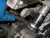
Here you can see my breaker bar and T40 Torx socket, attempting to break free the first of the cam bearing cap bolts. And you can see the resulting dead socket (exchanged at my neighborhood Craftsman tool store ... about 1.5 miles away....). It takes A LOT of torque to break off a socket this large, and I was still not able to budge the cam bearing cap bolt. It will be interesting to see what the machine shop finds, but I bet (based on what I saw on the front timing cover bolt threads) that the prior mechanic had used Loctite on those caps, and evidently torqued them down far more than the specified 21 Nm. I ordered 28 new Torx cam bearing cap bolts from MB -- they are around $1.50 apiece, so not too expensive.
IMG_3739.JPG IMG_3741.JPG


Since I decided not to push my luck with permanently damaging the cam bearing cap bolts, and let Scroggins Machine take care of this, I elected to remove the cylinder head. It is held on with 14 XZN bolts (also known as "triple-square"). I obtained the MB socket (made by Hazet) for this task. The head bolts were on quite tight, but I was able to get them with not too much effort.

The head bolts have to be removed in stages, in the reverse order of installation. This means that you start at the rear corner (bolt #14) and work your way inward in sort of a circular pattern. I loosened each bolt about 1 turn, then moved on to the next one, and then started over and finished loosening and removing each one. My daughter Sofia helped me bag each of the head bolts in a marked bag. These will be replaced with brand-new bolts (which were ordered on Wednesday from MB), but I will measure the stretch of each of the old bolts to see if they are within the specified 3mm of stretch.
IMG_3745.jpg IMG_3746.jpgIMG_3747.jpg

To remove the two rear-most head bolts, I opted to remove the central inner firewall section (this will be replaced due to damage, and will be on my final parts order as a cosmetic item) and the drains at the bottom of the windshield. When I re-assemble all of these items, I will replace the dust filters (seen in the photo below) with new ones from my stock, and I will lubricate the windshield washer arms with lithium grease. They are still decently greased from when I replaced the blower motor and regulator assembly several years ago, but "since I am in there" it makes sense to lubricate everything again.
IMG_3742.JPG IMG_3743.JPG IMG_3744.JPG


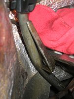
Before removing the cylinder head from the block, after the head bolts were removed, there were a number of tasks that had yet to be performed. The first one, was the removal of the transmission fluid dipstick, which was held to the rear corner of the cylinder head by a single Allen bolt. This was fairly rapidly, but tediously, achieved, simply because the area was too tight to get an Allen socket in there, so I had to use the short end of an Allen key.
IMG_3748.jpg IMG_3749.jpg IMG_3750.JPG


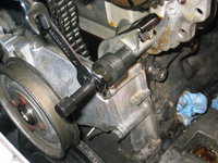
Next, the pin holding the upper timing chain guide rail (on the driver's side of the cylinder head) had to be removed, so I pulled out my trusty pin-puller (purchased and used for my M117 build several years ago) to slowly and carefully pull it out of the cylinder head.
IMG_3751.JPG IMG_3753.JPG


That was about all for Wednesday night. Today (Thursday), a new day dawned, and after work I went out to the shop and got started about 7:30 PM. But before doing this, it was sort of an early Christmas at the Van Zandt home, with seven (yes, SEVEN) boxes arriving via FedEx from the cavernous parts warehouses of MBUSA, to my front hallway.
IMG_3755.jpg IMG_3756.jpg


I was able to break the cylinder head loose from the block with my bare hands, but before I was able to REMOVE the head, one more task still remained. This was the removal of a plate on the rear, driver's side corner of the cylinder head, held on by two 5mm Allen bolts, that served as a bracket and also a nipple for one of the heater hoses coming from the firewall, to clamp onto. So, standing in the engine bay and kneeling on the top of the head, I loosened the ring clamp on the heater hose with a screwdriver, and worked the hose off of the nipple.

THEN, it was time to CAREFULLY lift the cylinder head off of the block. It was VERY HEAVY with the two cams still installed, but quite heavy even without them. And SO much larger than the M117 heads !! I lifted the head out, rested it temporarily on the fender and coolant reservoir (on top of an old pair of coveralls), clambered out of the engine bay onto the shop floor, and then lifted the head down and put it onto two plastic bags I'd laid out (on top of a moving blanket) on the shop floor.
IMG_3757.JPG


Let's take a couple of looks at the block, immediately after the head was removed, as I pick off the used head gasket. The head gasket does NOT look to be the latest, corner-reinforced model that MB just sent me. I will do a detailed, side-by-side comparison later.
IMG_3758.JPG IMG_3759.JPG IMG_3760.JPG


Here are some close-up photos of the insides of the cylinders, and the tops of the pistons and block. You can still see the cross-hatching in the cylinder walls, even after 202,000 miles.
IMG_3761.JPG IMG_3762.JPG IMG_3763.JPG


The next task, was to finally remove the pesky EGR tube. Here I am lifting it out of the engine compartment (an easy job with the head removed; I need to remember to "re-install" it before replacing the head), and examining the inside of the intake manifold end of the tube. You can see that it is 80-90% blocked with carbon. I had reamed it about a year ago down THROUGH the throttle body, which unblocked it enough to stop the :cel: lights, but it was only a matter of time before things built up again to be totally plugged.

I will soak the end of this tube in a gnarly solvent to loosen and then remove the build-up of carbon. I have decided NOT to purchase a new tube, as they are somewhere around $140.00 new...although I understand the design of the end of the tube has been modified to reduce or eliminate the periodic carbon build-up.
IMG_3764.JPG IMG_3765.JPG IMG_3767.JPG


A few more views of the engine bay, after the head was removed.
IMG_3768.JPG IMG_3769.JPG IMG_3770.JPG

You can certainly see the wetness on the rear of the block, underneath the passenger rear corner of the cylinder head. This is a CLASSIC location for oil leaks on the M104 (in addition to the upper timing chain cover at the "Bermuda Triangle" locations).
IMG_3771.JPG


And, a few final views of the preparation of the cylinder head for transport to the machine shop. Specifically, removal of the bracket at the rear corner (the lower bolt is pretty much inaccessible due to the heater hose when it's connected), and the spark plugs removed from the head.
IMG_3772.JPG IMG_3773.JPG IMG_3774.JPG IMG_3775.JPG


The refurbished fuel injectors are scheduled to be delivered from Deatschwerks in Oklahoma City tomorrow (Friday), so I will post the before and after reports on the flow and condition of the injectors. They called me on Wednesday to tell me that everything generally checked out fine and there were no problems.

The powder coater called and left me a message today to let me know that the valve cover and battery tray are ready for pickup, so I'll be stopping by on my way back from downtown Houston to drop the cylinder head and lower intake manifold at Scroggins Machine, to pick up those parts.

My replacement MB ETA (throttle body) will be delivered to my home next Tuesday. So, I am expecting that by next Friday, December 20th, I should have all of the pieces in place to begin re-assembly of the engine. My last parts order was made today, and will be delivered during the middle of next week. Everything is hopefully coming together, and my original estimate of 4-5 weeks of the car being down, is still holding up at this point.

While the cylinder head is in the machine shop, I have A LOT of cleaning work to do, not only on the exterior of the block, but also on the tops of the pistons and on the sealing surfaces on the front of the block, upper timing cover (both mating to the block as well as at the cam solenoid sealing surface), and general cleanup of the parts removed from the car. I'll be firing up my parts washer very soon.....

Til' next time!

Cheers,
Gerry
 
Re: M104 / W124 Top-End Rebuild

Slacker!

Fuel injected engines seem to last much longer than carbureted motors. Not mention an engine that is routinely maintained at the highest level. Still remarkable for a motor with 202K.

Very nice work and write up. My hat is off to you.
 
Last edited:
Re: M104 / W124 Top-End Rebuild

Wow, those cam bolts are crazy! I wonder who the gorilla was who worked on it last? It really makes me wonder even more about the chain and the sprocket possibly being off a tooth.
 
Re: M104 / W124 Top-End Rebuild

Wow, those cam bolts are crazy! I wonder who the gorilla was who worked on it last? It really makes me wonder even more about the chain and the sprocket possibly being off a tooth.
Indeed. I have been scratching my head for the past 3 days about this. Am just thankful that the 104 head can be removed with the cams installed. This experience did not make me a big fan of Torx fasteners, either...
 
Re: M104 / W124 Top-End Rebuild

I'm 99% certain that the cam bolt issue was due to threadlocker. I guess we'll need to see what the machine shop finds when they extract the buggers!

:detective:
 
Re: M104 / W124 Top-End Rebuild

Today I picked up the valve cover items and the battery tray from Precision Powder Coating in Spring, TX. Here are a couple of quick photos I took as I put the items into the trunk of my 560SEC.
2013-12-13 11.58.16.jpg 2013-12-13 11.58.45.jpg 2013-12-13 11.58.29.jpg

Next, I drove the 30 miles due south, into the belly of the beast -- downtown Houston -- to pay a visit to Scroggins Machine to drop off the cylinder head and lower intake manifold.

Spent about 30 minutes chatting with Bobby Scroggins, the owner. He and his staff were having lunch, so had a bit more time than normal to talk. Bobby was quite stoked to see my 560SEC motor and was pleased to know that the head he refurbished 3.5 years ago have 32K miles on them and are still going strong !!

We talked about a wide range of topics, including the following:
  • He says a cursory look at the markings on the head would suggest that it HAS NOT been surfaced, despite likely being off the car in the past. He showed me the "maker's mark" and it was not machined down/off -- it was still pretty clear, which he believes means that the head gasket was just replaced in the past, no machine work was done
  • We discussed the situation with the Torx cam bearing caps being so tight. He said this is very common with the MB inline-six motors and he sees it all the time. He didn't think that thread-locker or anything else had been used on the cam bearing cap bolts, but rather because the heads of the Torx bolts are so large in diameter, there is a large area for them to exercise torque on the aluminum surface. He said it won't be any problem to remove the bolts
  • Overall he said the head looked in good condition, with the surface of the head looking good, valves in good nick, etc. They are going to clean and pressure test the head, and they will -- given the 200K+ mileage -- take a look at the valve guides. Although he said that valve guides are not generally an issue on the M104, he did say that there are occasions when a few of them will be a bit loose, so they will check all of them, and if they find any loose ones they will take the opportunity to press new ones in. Of course, they will replace the valve stem seals as a matter of course. This is all relatively incremental labor.
  • Bobby showed me several pairs of the current M272 and M273 cylinder heads that he and his team were working on. He said they are getting UNBELIEVABLE numbers of these heads coming into the shop for repair (the local Houston MB dealers are replacing them under warranty and shipping the returned ones in for rework and eventual resale). The main issue, as he showed me, are the valve guides in these motors. The original guides are cast metal, and they are not holding up. So he is having to replace them with bronze guides, which are more durable. He said the quality of materials in the newer MB motors is literally appalling, they are very poor.
  • He also showed me a pair of M113 cylinder heads. He said they are also pretty poor, but mainly because these engines are showing a sludge problem, and the quality of the materials is also not that great. He said that the M104, M119, M117 and M103 motors are all excellent quality, extremely durable, and overall very nice to work on. The M104/M119/M120 motors are much easier to work on with their hydraulic buckets, as opposed to the old-school follower setup of the M103 and M117.
  • It may take up to two weeks, depending on the amount of work that has to be done on my cylinder head. If anything new (like valve guides) need to be ordered, then it will introduce extra days into the process, but he said it would be about 2 weeks at the maximum.

Lastly, my refurbished injectors and flow report came today via FedEx from DeatschWerks in Oklahoma City. Everything was very nicely and professionally packaged. I have posted a photo (below) of the sealed injectors that were in the box, as well as PDF copies of the before and after flow test reports.
2013-12-13 14.19.36.jpg

I hope you find this interesting.

Cheers,
Gerry
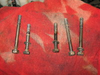
 

Attachments

Re: M104 / W124 Top-End Rebuild

I love shiny parts. That red matches very nicely to my SL (Magma). It looks like the injectors were in pretty good condition.
 
Re: M104 / W124 Top-End Rebuild

What years/models use the M272 and M273 engines? I'm not familiar with those...

:blink:
 
Re: M104 / W124 Top-End Rebuild

I am not a fan of those engines.

My mother in law just went through this with her 45k mile 2007 E350. MBUSA ultimately split the $6,000 bill with us.

M272 engines that were sold between 2004[1][2] and 2008 with engine serial numbers below 2729..30 468993 often show early wear of the balance shaft gears, requiring extensive repairs at a retail cost of over $4000. [3] [4] These complaints led to a class action lawsuit against Mercedes Benz (Greg Suddreth and Paul Dunton v. Mercedes-Benz USA, LLC), which alleged the M272 engines are equipped with defective balance shafts gears which "wear out prematurely, excessively and without warning, purportedly causing the vehicles to malfunction, the check engine light to illuminate and the vehicle to misfire and/or stop driving." [5] The suit further alleged that Mercedes knew of this problem, sending out repair bulletins on how to address this issue and ultimately changing the balance shaft gears to avoid this problem. This suit was ultimately dismissed with the judge agreeing with Mercedes that because the gears fail at 60 -80K miles and outside of the warranty period, Mercedes is not legally responsible for these problems. [6] A second class action lawsuit is being organized. [7]
 
Re: M104 / W124 Top-End Rebuild

Nice progress Gerry. Those new parts are going to look amazing when you get them back in. I love the little details like this!

And tell your garage assistant (Sofia) that we are looking forward to seeing her next weekend! While I have two older boys, Caroline (10) is the only one who hangs out with me in the garage. She especially likes helping me wash the cars. AND she is the one that goes to the MB dealer wholesale parts counter with me, takes a deep breath, and says "I love how this place smells!"
 
Re: M104 / W124 Top-End Rebuild

:update:

Today was the first day I actually got to REASSEMBLE something, rather than DISASSEMBLE. So, it is more or less a turning point, and with the cylinder head brought into the machine shop, I'd say I'm at the 50% mark overall now on the project.

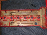
Specifically, I installed new rubber grommets onto the top of the valve cover, as well as a new sticker (which was slightly cut as received from MBUSA, so I'll probably spring for a more perfect one on my next order, as it's a cheap sticker). I also re-installed the aluminum baffles that bolt up to the underside of the valve cover, as well as replacing the internal pieces that separate the baffle compartment.

Specifics are below.

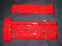
Before we get started, here are a few photos of the powder coated pieces ... the two valve cover pieces, and the top and underside of the battery tray.
IMG_3776.JPG IMG_3777.JPG IMG_3778.JPG


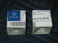
First, I removed the grommets from their small MB boxes. These grommets seal the gap where the plastic air crossover tube acquires PCV vapors into the intake air that is passing from the air filter and MAF sensor, to the ETA to be admitted into the engine.
IMG_3779.JPG IMG_3780.JPG IMG_3781.JPG IMG_3782.JPG


Then, I pressed the grommets into the freshly painted valve cover.
IMG_3783.JPG IMG_3784.JPG IMG_3785.JPG


Here's a view of the both grommets, installed.
IMG_3786.jpg


Next, the warning sticker on the valve cover. I'd installed the sticker specified by the EPC, but it is NLA and has been superseded to this smaller, 204 part number. The one I received from MB was slightly sliced up on the bottom, so I'll obtain a new one at some point.
IMG_3787.JPG IMG_3788.JPG IMG_3789.JPG


After that, it was time to re-install the metal and aluminum baffles that screw into the bottom of the valve cover. First, I did a test fitment, so that I was sure how everything went back together. Having my dis-assembly and removal photos also helped things, from a visual perspective.

Before I got started, I had to ensure that I had a perfectly clean environment. So, I had to remove the old sealant from the grooves, and from the bottom of the baffle. It was apparent that the factory had used black RTV sealant. I opted to use a Permatex Red high-temp RTV sealant, which can easily withstand temperatures of 650F and higher, and is specified for valve covers among many other applications.

I cleaned out the old RTV from the channels and from the baffles themselves with a pick tool (channels) and a brake-cleaner-soaked rag (aluminium baffle pieces).
IMG_3790.JPG IMG_3792.JPG


Test-fitting the plastic baffles that go UNDER the metal baffle covers.
IMG_3793.JPG IMG_3794.JPG IMG_3795.JPG IMG_3796.JPG


And here is final prep and application of the Permatex Red RTV to the underside of the baffle covers.
IMG_3797.JPG IMG_3798.JPG IMG_3799.JPG


And finally, the baffle covers mounted to the underside of the valve cover. All it needs to go back on the car now, is the outside valve cover gasket, and the six round gaskets that encircle the spark plug wells and keep oil away from the plugs. I'll apply these gaskets (which are part of the valve cover gasket kit) after the cylinder head has been installed and the engine and cam timing has been triple-checked.
IMG_3800.JPG
 
Re: M104 / W124 Top-End Rebuild

Gerry, FYI, the original ignition decals are available from the Classic Center. Click here, see post #12 and #14. I think you can only get these from the Classic Center though. I got a few from Tom, if you want I'll include one when I return the manuals you loaned me last year... then your valve cover will have period correct decals!

:woot:
 
Re: M104 / W124 Top-End Rebuild

Sure, thanks! Let me know how much money to put in the package that I'll be sending you.
 
Re: M104 / W124 Top-End Rebuild

:update:

Tonight was relatively quiet in the shop. I spent about an hour starting the job of cleaning off the top deck of the block, and cleaning the tops of the pistons. I used brake cleaner and carb/choke cleaner (which is a little stronger than brake cleaner) for this task. along with a razor blade, and a plastic scraper.

One has to be exceedingly careful with the razor blade on the top of the piston, because the razor blade can scratch/scrape/score the top of the piston. It's OK on the harder block surface, but even then you have to use a very shallow angle on the blade to scrape the crud off of the surface. The plastic scraper works well for getting into the valve recesses cast into the piston crowns. I wasn't 100% anal and got every speck of crud off the piston, but I got 98% of it, and that was good enough for me. I would say that doing a single piston, and the area between the end of the block (including part of the channel where the front timing cover seal will set into) took me about one hour of diligent work to do.

I'll plan to do 1-2 pistons and the surrounding block area per night, this week. This is a really critical step so that the new head gasket will seal properly. When everything is scraped, I'll blow out the pistons and water jacket areas as best I can with compressed air. For successive nights, I'll also try to mask off the water jacket areas so that it minimizes the amount of crud from the block surface that falls into them. Lastly, I'll blow out the head bolt holes and then clean and chase them with a tap, to ensure proper torque when it is time to re-install the cylinder head.

First of all, here is a photo of piston #1's crown, immediately after removing the cylinder head the other night. This is what I was starting from.
IMG_3761.JPG


Here are a few photos of the #1 piston crown, as I finished up for the night. You can see the date code "11/94" stamped into the piston.
IMG_3810.JPG IMG_3811.JPG IMG_3812.JPG IMG_3813.JPG
 
Re: M104 / W124 Top-End Rebuild

He said the quality of materials in the newer MB motors is literally appalling, they are very poor.

That makes me happy to have M119 engines. I guess they stopped the quality thing in the late nineties?

Great pics, Gerry.
 
Re: M104 / W124 Top-End Rebuild

That makes me happy to have M119 engines. I guess they stopped the quality thing in the late nineties?

Great pics, Gerry.
I think MB stopped being an engineering-driven company (with cost and quality being a secondary consideration) in the very early 1990s -- key decisions being made in the 1990-1992 time frame, and taking a few years to begin to filter down into the various product lines, and small/large business decisions being made as a result.

At that point, designing product to a cost became more important than the "cost no object" philosophy that had guided the company up to that point. For some product lines, decisions were relatively quick, and had a fairly rapid implementation/impact; in other cases, changes weren't phased in until the next product line or model refresh. Some of the quicker results of this were (for example) the move from closed-deck to open-deck blocks on the M119, which happened in the 1993 time frame.

In the case of the W140 S-Class, which first appeared in 1991 as a 1992 model, and was the very last MB model that was developed "cost no object," there was a mid-cycle refresh of the W140 design, I think for the 1995 or 1996 model year, that simplified the car's systems somewhat and introduced a host of changes under the skin that made the car significantly cheaper to produce (and thus MB took less of a loss on each vehicle). It is strongly rumoured that the cost of engineering and development of the W140 was so high, that MB never made any money on the car through its entire production lifetime. The W140 was actually curtailed a couple of years early due to rather low sales, particularly compared to the preceding W126 S-Class. Interestingly, the Maybach models introduced in the early 2000s were based on a modified W140 platform, and NOT the W220 platform that was in production at the time.

In the case of the M104, that engine continued production through the 1997 model year (so probably most engines were produced by late 1996), but the successor M112 product cycle and engineering decisions were likely made in the 1991-1992 time frame at the outset of development (it takes a number of years to develop and test a new engine family).

The M112 (V-6) and M113 (V-8) were very definitely developed to a cost, and also for ease of manufacturability (produced on the same assembly line) and low emissions. The decision to move from an inline-six design to a V-6 was also partially done for cost reasons, and partially for space savings (shorter hood and lower frontal area). I have heard in the past few weeks that MB is in final testing on a brand-new line of inline-six engines, and will be going BACK to an in-line six design in the very near future. Interestingly, BMW has never stopped producing an inline-six.

Fundamentally, an in-line six is a better-balanced engine, and the harmonic balancing system on the M112 has been a major reliability issue with this motor ever since it was first produced.
 
Re: M104 / W124 Top-End Rebuild

I think one of the ONLY positives of the required taller hood/front end for safety reasons is that companies can go back to inline-6 engines. I really do hate how tall cars have gotten though...
 
Re: M104 / W124 Top-End Rebuild

:update:

Here's a post with some random notes and musings I've been thinking about for the past couple of days, as my top-end rebuild progresses. I hope y'all find these of interest, and some relevance to the E500E world.

First, the first box from my third (and next to last) parts order rolled in today. Inside the box were my 28 new cam bearing cap bolts, which (per your thought Michael) are exactly the same as the ones that are currently holding the bearing caps onto the head. I also received 11 of the 14 new head bolts -- I assume the other three will be in the second package, arriving from MB's Carol Stream, IL warehouse tomorrow (Tuesday). As I'm now on Christmas holiday for the rest of the year, I've plenty of time to enjoy working on the car out in the shop.

One of the parts that came in today's box were the copper exhaust manifold nuts. These nuts are a "one-use" nut, meaning that they are discarded upon removal from the car, and new ones are supposed to be used. The interesting thing about them is that they are shaped slightly differently than most other nuts. Take a look at the photos below. Can you see what is different from most ordinary nuts?
IMG_3815.JPG IMG_3816.JPG


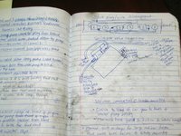
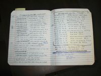
I've received a couple of PMs and comments here from folks who are interested how I keep records of what I do. Well, besides the photographic record, I maintain a log in an ordinary student composition notebook (the ones with the black and white speckled cover) with all steps performed, as I do them. I also record the following things, on separate pages and in the margins:
  • time worked during each day's session
  • description of any parts broken/cracked during removal, that require replacement
  • number of cups of coffee and 60oz sodas consumed during working hours
  • comprehensive list of part numbers & descriptions for parts orders
  • any handy notes, such as torque values, part quantities, thread pitches, etc. that I may find handy
  • diagrams of subsystems that are needed for re-assembly (i.e. vacuum line or wire bundle routings & placement)
Here are a couple of photos of some of my notes from this project:
IMG_3817.JPG IMG_3818.JPG


Next, one of the things I'll be doing is replacing the timing chain. I had ordered (via AHAZ) an IWIS chain (MB OEM) and I opened it up to see what kind of master link it had -- there are a couple of different kinds. Indeed, it is the "plate" type and I am going to need to borrow my mechanic's chain riveter/press to install the new chain - basically to crimp down the end links to keep the center and edge plates in the proper place on the chain. It's a fairly easy operation, but the tool is very specialized, and last I checked around $800 from MB. It will be basically an overnight use for me -- my mechanic doesn't use it all that often.
IMG_3819.JPG IMG_3820.JPG IMG_3822.JPG

And here are a few photos of me on my continuing clean-up of the pistons. This is a view of cylinders #3 (right) and #4 (left) at the beginning of (#3) and before (#4) the piston crown cleanup process. Basically this is a lot of elbow grease and patience, and takes about 30 minutes to clean 80-90% of the baked-on carbon from the piston. Most of this time you are hunched over the fender or radiator, or in my case sitting on top of the ABS pump (it's nice and flat, though not very comfortable) and leaning over the now exposed block.
IMG_3823.JPG IMG_3824.JPG IMG_3825.jpg

And lastly..... an investigation of the wiring in the cable for the ORIGINAL ETA that was in the car. This ETA, as you can see from the first photo below, is dated November of 1994, so was the original unit. It was working just fine when removed, but it was only a matter of time before it would have shorted out and caused problems. And after opening it up ... I am doubly glad that I did this job now. Now remember, this ETA had ONLY been removed and had been fairly gently handled since removal, spending most of its time sitting on the garage floor.

You can see what the situation was, when I slit open the wiring cable. The photos pretty much speak for themselves. To say I was living on borrowed time, is an understatement.
IMG_3827.JPG IMG_3828.JPG IMG_3829.JPG IMG_3830.JPG IMG_3831.JPG


This ETA biodegradeable wiring situation shown above (both wiring in the external cable bundle and inside the housing) is also a common problem with the E500E, given enough time and mileage.

Just wanted you guys to see this.

Cheers,
Gerry
 
Re: M104 / W124 Top-End Rebuild

1) The copper nuts are the compression self-locking style. The outer side is pinched. Similar nuts are used for the front sway bar brackets, btw.

2) The master link with the Iwis chain likely has a slide-on center and outer plate. The OE link has a press-on outer plate, that must be pressed in place with the tool, before the pins are crimped/swaged to hold it in place.

:pc1:
 
Re: M104 / W124 Top-End Rebuild

The following is a list of parts that I have ordered for my Top-end Rebuild:

[TABLE="class: grid, width: 800, align: left"] [TR] [TD]Part Number
[/TD] [TD]MB Description
[/TD] [TD]Function/Location
[/TD] [TD]Price
[/TD] [TD]Quantity
[/TD] [/TR] [TR] [TD]104 990 00 12[/TD] [TD]SCREW[/TD] [TD]M104 head bolt[/TD] [TD]$4.68[/TD] [TD]14[/TD] [/TR] [TR] [TD]120 050 02 11[/TD] [TD]TENSIONER[/TD] [TD]Timing chain tensioner[/TD] [TD]$120.00[/TD] [TD]1[/TD] [/TR] [TR] [TD]124 682 05 26[/TD] [TD]INSULATION[/TD] [TD]center hood foam piece behind grill (for E500)[/TD] [TD]$41.40[/TD] [TD]1[/TD] [/TR] [TR] [TD]010 542 57 17[/TD] [TD]SENDER UNIT,[/TD] [TD]intake air temp sender[/TD] [TD]$15.60[/TD] [TD]1[/TD] [/TR] [TR] [TD]104 142 04 80[/TD] [TD]GASKET,EXHST[/TD] [TD]EGR valve gasket[/TD] [TD]$5.04[/TD] [TD]1[/TD] [/TR] [TR] [TD]120 142 00 72[/TD] [TD]NUT[/TD] [TD]copper exhaust manifold nut[/TD] [TD]$1.44[/TD] [TD]23[/TD] [/TR] [TR] [TD]002 990 11 22[/TD] [TD]SCREW[/TD] [TD]intake manifold bolts to cylinder head[/TD] [TD]$2.88[/TD] [TD]5[/TD] [/TR] [TR] [TD]017 997 16 48[/TD] [TD]SEAL RING,OI[/TD] [TD]oil dipstick o-ring[/TD] [TD]$1.20[/TD] [TD]1[/TD] [/TR] [TR] [TD]006 997 26 45[/TD] [TD]SEAL RING,VL[/TD] [TD]oil dipstick o-ring[/TD] [TD]$1.20[/TD] [TD]1[/TD] [/TR] [TR] [TD]117 078 02 81[/TD] [TD]HOSE,VACUUM[/TD] [TD]rubber vacuum connectors[/TD] [TD]$2.16[/TD] [TD]4[/TD] [/TR] [TR] [TD]104 052 07 74[/TD] [TD]PIN,CYLINDER[/TD] [TD]timing chain guide rail pin to cylinder head[/TD] [TD]$7.50[/TD] [TD]1[/TD] [/TR] [TR] [TD]000007 008103[/TD] [TD]CYLINDRICAL[/TD] [TD]timing chain guide rail lower pin to engine block[/TD] [TD]$2.28[/TD] [TD]1[/TD] [/TR] [TR] [TD]002 989 47 20 10[/TD] [TD]SEALING COMP[/TD] [TD]sealant for timing chain cover to cylinder head[/TD] [TD]$22.20[/TD] [TD]1[/TD] [/TR] [TR] [TD]120 990 02 21[/TD] [TD]SCREW,CYLIND[/TD] [TD]cam bearing cap bolt[/TD] [TD]$1.56[/TD] [TD]28[/TD] [/TR] [TR] [TD]019 997 13 48[/TD] [TD]SEAL RING[/TD] [TD]fuel injector o-rings[/TD] [TD]$2.88[/TD] [TD]12[/TD] [/TR] [TR] [TD]
[/TD] [TD]IGNITION COIL[/TD] [TD]ignition coil pack[/TD] [TD]
[/TD] [TD]1[/TD] [/TR] [TR] [TD]003 997 17 94[/TD] [TD]TIMING CHAIN[/TD] [TD]IWIS timing chain[/TD] [TD]
[/TD] [TD]1[/TD] [/TR] [TR] [TD]035 121 11 19
[/TD] [TD]SEAL RING[/TD] [TD]o-ring for thermostat[/TD] [TD]
[/TD] [TD]1[/TD] [/TR] [TR] [TD]110 200 05 15[/TD] [TD]THERMOSTAT[/TD] [TD]thermostat 87C[/TD] [TD]
[/TD] [TD]1[/TD] [/TR] [TR] [TD]
[/TD] [TD]
[/TD] [TD]serpentine belt[/TD] [TD]
[/TD] [TD]1[/TD] [/TR] [TR] [TD]
[/TD] [TD]
[/TD] [TD]spark plug, Bosch F8DC4[/TD] [TD]
[/TD] [TD]6[/TD] [/TR] [TR] [TD]119 589 00 10 00[/TD] [TD]SCREWDRIVER[/TD] [TD]short XZN Hazet socket for M104 head bolts[/TD] [TD]$22.20[/TD] [TD]1[/TD] [/TR] [TR] [TD]000 092 10 80[/TD] [TD]GASKET,FUEL[/TD] [TD]foam ring at airbox mouth[/TD] [TD]$3.84[/TD] [TD]1[/TD] [/TR] [TR] [TD]007603 014104[/TD] [TD]RING,GENERAL[/TD] [TD]vacuum line to brake booster sealing ring
[/TD] [TD]$1.08[/TD] [TD]1[/TD] [/TR] [TR] [TD]104 141 13 80[/TD] [TD]GASKET,INTAK[/TD] [TD]EGR gasket at tube end[/TD] [TD]$1.92[/TD] [TD]1[/TD] [/TR] [TR] [TD]117 078 04 81[/TD] [TD]HOSE,THROTTL[/TD] [TD]EGAS vacuum line (ETA)[/TD] [TD]$3.48[/TD] [TD]1[/TD] [/TR] [TR] [TD]117 078 02 81[/TD] [TD]HOSE,VACUUM[/TD] [TD]vacuum connector[/TD] [TD]$2.16[/TD] [TD]1[/TD] [/TR] [TR] [TD]015 997 39 48[/TD] [TD]SEAL RING,EN[/TD] [TD]oil level sensor o-ring[/TD] [TD]$2.04[/TD] [TD]1[/TD] [/TR] [TR] [TD]017 997 58 48[/TD] [TD]SEAL RING,SE[/TD] [TD]oil level sensor o-ring[/TD] [TD]$1.20[/TD] [TD]1[/TD] [/TR] [TR] [TD]104 016 03 64[/TD] [TD]CYLINDER HEA[/TD] [TD]o-rings for valve cover gasket bolts[/TD] [TD]$3.36[/TD] [TD]12[/TD] [/TR] [TR] [TD]124 470 67 75[/TD] [TD]FUEL HOSE,VL[/TD] [TD]fuel return hose[/TD] [TD]$24.00[/TD] [TD]1[/TD] [/TR] [TR] [TD]124 470 79 75[/TD] [TD]FUEL HOSE,VL[/TD] [TD]fuel supply hose from fuel cooler[/TD] [TD]$30.00[/TD] [TD]1[/TD] [/TR] [TR] [TD]601 078 06 45[/TD] [TD]BRANCH-OFF F[/TD] [TD]dual-outlet rubber vacuum connector[/TD] [TD]$7.20[/TD] [TD]1[/TD] [/TR] [TR] [TD]204 584 00 47[/TD] [TD]GUIDE SIGN[/TD] [TD]yellow sticker for valve cover[/TD] [TD]$2.16[/TD] [TD]1[/TD] [/TR] [TR] [TD]104 010 21 30[/TD] [TD]CYLINDER GAS[/TD] [TD]valve cover gasket set[/TD] [TD]$56.40[/TD] [TD]1[/TD] [/TR] [TR] [TD]104 010 37 20[/TD] [TD]CYLINDER HEA[/TD] [TD]cylinder head gasket set[/TD] [TD]$118.80[/TD] [TD]1[/TD] [/TR] [TR] [TD]617 589 00 10 00[/TD] [TD]SOCKET[/TD] [TD]Long XZN socket (Stahlwille) for head bolts[/TD] [TD]$24.60[/TD] [TD]1[/TD] [/TR] [TR] [TD]002 989 45 20 10[/TD] [TD]SEALING COMP[/TD] [TD]MB sealant for ends of timing cover gasket[/TD] [TD]$36.00[/TD] [TD]1[/TD] [/TR] [TR] [TD]000 092 25 60[/TD] [TD]SEAL RING, FU[/TD] [TD]MAF o-ring at airbox[/TD] [TD]$3.84[/TD] [TD]1[/TD] [/TR] [TR] [TD]000 995 60 44[/TD] [TD]CLAMP[/TD] [TD]light blue cable clamp[/TD] [TD]$3.36[/TD] [TD]2[/TD] [/TR] [TR] [TD]000 995 52 44[/TD] [TD]CLAMP[/TD] [TD]light blue cable clamp[/TD] [TD]$5.28[/TD] [TD]2[/TD] [/TR] [TR] [TD]117 997 05 82[/TD] [TD]HOSE,VACUUM[/TD] [TD]1 meter red rubber vac hose for EGR system[/TD] [TD]$16.80[/TD] [TD]1[/TD] [/TR] [TR] [TD]000000 004138[/TD] [TD]SCREW[/TD] [TD]fan clutch bolt[/TD] [TD]$4.44[/TD] [TD]1[/TD] [/TR] [TR] [TD]012 997 51 48[/TD] [TD]SEAL RING,WA[/TD] [TD]o-ring for end of crossover water pipe[/TD] [TD]$1.20[/TD] [TD]1[/TD] [/TR] [TR] [TD]012 545 04 28[/TD] [TD]PIN BUSHING[/TD] [TD]two-prong electrical connector[/TD] [TD]$1.44[/TD] [TD]8[/TD] [/TR] [TR] [TD]005 997 62 90[/TD] [TD]LOOM TIE[/TD] [TD]zip ties that press into chassis[/TD] [TD]$1.20[/TD] [TD]2[/TD] [/TR] [TR] [TD]011 545 71 28[/TD] [TD]PIN BUSHING[/TD] [TD]two-prong electrical connector[/TD] [TD]$2.28[/TD] [TD]2[/TD] [/TR] [TR] [TD]104 016 09 80[/TD] [TD]GASKET,VALVE[/TD] [TD]cam cover air breather hole rubber gasket[/TD] [TD]$9.30[/TD] [TD]2[/TD] [/TR] [TR] [TD]017 997 21 48[/TD] [TD]SEAL RING,VL[/TD] [TD]timing cover oil seal o-ring[/TD] [TD]$3.00[/TD] [TD]1[/TD] [/TR] [TR] [TD]104 052 14 16[/TD] [TD]SLIDING RAIL[/TD] [TD]top triangular sliding chain rail[/TD] [TD]$6.60[/TD] [TD]1[/TD] [/TR] [TR] [TD]007603 027101[/TD] [TD]RING,GENERAL[/TD] [TD]timing chain tensioner gasket[/TD] [TD]$1.20[/TD] [TD]1[/TD] [/TR] [TR] [TD]104 050 14 16[/TD] [TD]SLIDING RAIL[/TD] [TD]timing chain guide rail[/TD] [TD]$32.40[/TD] [TD]1[/TD] [/TR] [TR] [TD]104 050 15 16[/TD] [TD]SLIDING RAIL[/TD] [TD]timing chain tensioner rail[/TD] [TD]$46.20[/TD] [TD]1[/TD] [/TR] [TR] [TD]104 094 01 91[/TD] [TD]SEAL BOOT,BR[/TD] [TD]corrugated rubber boot at crossover pipe & MAF[/TD] [TD]$24.60[/TD] [TD]1[/TD] [/TR] [TR] [TD]104 141 07 80[/TD] [TD]GASKET,INTAK[/TD] [TD]ETA gasket to intake manifold[/TD] [TD]$1.56[/TD] [TD]1[/TD] [/TR] [TR] [TD]104 094 35 82[/TD] [TD]HOSE,AIR CLE[/TD] [TD]intake air hose, large[/TD] [TD]$10.50[/TD] [TD]1[/TD] [/TR] [TR] [TD]104 094 36 82[/TD] [TD]HOSE,AIR CLE[/TD] [TD]intake air hose, small[/TD] [TD]$7.80[/TD] [TD]1[/TD] [/TR] [TR] [TD]104 990 02 78[/TD] [TD]CONNECTOR,IN[/TD] [TD]small air hose connector (aluminum)[/TD] [TD]$2.64[/TD] [TD]1[/TD] [/TR] [TR] [TD]104 141 17 83[/TD] [TD]HOSE,INTAKE[/TD] [TD]large-diameter hoses that mate intake halves[/TD] [TD]$28.20[/TD] [TD]2[/TD] [/TR] [TR] [TD]104 141 11 80[/TD] [TD]GASKET,INTAK[/TD] [TD]resonance valve gasket[/TD] [TD]$4.32[/TD] [TD]1[/TD] [/TR] [TR] [TD]104 015 02 20[/TD] [TD]GASKET,VL R[/TD] [TD]timing cover u-shaped gasket (extra)[/TD] [TD]$7.80[/TD] [TD]1[/TD] [/TR] [TR] [TD]
[/TD] [TD]
[/TD] [TD]
[/TD] [TD]
[/TD] [TD]
[/TD] [/TR] [TR] [TD]
[/TD] [TD]
[/TD] [TD]
[/TD] [TD]
[/TD] [TD]
[/TD] [/TR] [/TABLE]
 
Back
Top