• Hi Guest !

    Welcome to the 500Eboard forum.

    Since its founding in late 2008, 500Eboard has become the leading resource on the Internet for all things related to the Mercedes-Benz 500E and E500. In recent years, we have also expanded to include the 400E and E420 models, which are directly related to the 500E/E500.

    We invite you to browse and take advantage of the information and resources here on the site. If you find helpful information, please register for full membership, and you'll find even more resources available. Feel free to ask questions, and make liberal use of the "Search" function to find answers.

    We hope you will become an active contributor to the community!

    Sincerely,
    500Eboard Management

HOW-TO: Complete W124 Sunroof Refurbishment

Part 5- Re-assembly and final adjustments for smooth operation

This is the final section of the DIY which details re-assembling the sunroof and making some adjustments as you go to ensure the lid position is correct when closed and for smooth operation.

The adjustment stages are not 100% required but they are recommended when doing a full rebuild like this. To carry out adjustment you will need some vernier callipers (For centering the panel) and for setting the rear lid height adjustment a pair of regular 6mm drill bits are acceptable. If you have replaced the lift arms, sunroof lid or did not make complete markings of the bolts as you went then additional tools will be needed from Mercedes; (Courtesy of w124 performance)

View attachment 61793

I could simply say – “assembly is the reverse of removal”- which for the most part is true. However in the following steps I will detail the ‘full’ re-assembly and adjustment steps I would recommend-

1: Lubricate the section of rail pictured below of both sides with a light coating of Gleitpaste. Set the lift arms back in and slide them backwards out of the way

View attachment 62374 View attachment 62375 View attachment 62376

2: Lubricate the channel in the side trims as pictured and re-install.

View attachment 62377 View attachment 62378

Make sure the lift arm is correctly seated into the side channels-

View attachment 62379

3: Re-install the transport bridge and tighten the bolts back to the original markings made before removal

View attachment 62380 View attachment 62381

4: Re-install the gutter and don’t forget the little fibre washers first. Apply light oil to these connections

View attachment 62382 View attachment 62383 View attachment 62384

5: Now install the 4x remaining new felt pads onto the sunroof lid. I find it easier to Gleitpaste the back side first of each new felt pad then fit on and Gleitpaste the remaining sides.

View attachment 62385 View attachment 62386 View attachment 62387 View attachment 62388

6: Fit the MB tools both sides as pictured. (The tools are handed and marked L /R)

View attachment 62389 View attachment 62390 View attachment 62391

7: Set the Sunroof Lid back into place

8: Now to check / adjust the side to side placement of the lid in the opening. Loosen the front most 4x 8mm bolts as pictured (2x per side) Use the callipers to check both gaps and adjust as required before re-tightening the bolts again.

View attachment 62393 View attachment 62392

9: Re-fit the top sunroof lid nuts back on to the original markings made on disassembly.

View attachment 62394

10: Check the rear lid height. Mine was low both sides. Slacken the bolts pictured and lift the lid up to the correct height before re-tightening. This can take several attempts to get just right. Do this on both sides obviously. Then once set- remove the red tools both sides.

View attachment 62395 View attachment 62396 View attachment 62397

11: Now it’s time to fine adjust the sunroof lid front height in the opening. (This must be done now prior to the Stainless trims going back on) One screw as pictured both sides adjusts the front height. Again mine was low here too prior to adjustment.

View attachment 62398 (Note- I forgot this pic and took it after the trims were installed - it should not be adjusted with the trim plates on!)

12: Slide the lid back to open. Apply a light coating of Gleitpaste to the underside of the top stainless trim as pictured and re-fit the stainless trims both sides.

View attachment 62399 View attachment 62402 View attachment 62400 View attachment 62401

13: Now lubricate and adjust the front anti draught flap. Lightly oil all of the hinge parts and the top of the trim here-

View attachment 62403

Then there are 2x adjustment screws. This one adjusts the ‘stand up’ height with the roof open-

View attachment 62404

And these small screws adjust the flap in the lowered position as the roof is closing the last few inches. I find these always need tweaking to stop the flap rubbing on the lid as it closes.

View attachment 62405

13: Roll the lid fully closed and make sure both plastic brackets are positioned as shown below-

View attachment 62406

14: Re-install the fabric liner by inserting from outside. Set it in first – then check inside that the channel lines up before pushing it back in.

View attachment 62407 View attachment 62408

Roll the lid forward again about 3 – 4 inches and re-pop on the 4x plastic clips. Check that the fabric liner is correctly attached by using the ‘tilt up’ function of the sunroof. It may take several attempts to get both sides to ‘catch’ on the fabric liner brackets correctly. (It took me 4x goes on this one!)


And that is it! One re-assembled sunroof – and you CAN do it at home. It’s a half day’s tinkering for a DIY’er and highly recommended to do it sooner than later before the sunroof might stop working / jamb given that 99% of w124’s will have never had the felt pads replaced or the sunroof overhauled like this. If your sunroof is making any kind of scraping / groaning noises STOP using it until overhauled.

If it breaks a lift arm and won’t open it’s a whole lot of trouble – I will detail that kind of repair in a couple months.
Question on step #3. The reinstall of the transport bridge (the L-shaped part) I noticed that there are two sets of holes side by side. Your pic shows using the ones that are closest to the outer edge. Both my factory cars have the original "washer mark" where the black paint has a silver round scuff where the screwhead used to be on the other set of holes instead. Is that a goof or what is the difference? I circled where mine both mount in red, you're using the other spot. Where should it be? 1659281422639.png
 
Question on step #3. The reinstall of the transport bridge (the L-shaped part) I noticed that there are two sets of holes side by side. Your pic shows using the ones that are closest to the outer edge. Both my factory cars have the original "washer mark" where the black paint has a silver round scuff where the screwhead used to be on the other set of holes instead. Is that a goof or what is the difference? I circled where mine both mount in red, you're using the other spot. Where should it be? View attachment 151325

IIRC, the alternate set of holes is used on the C124 (coupé). Should be noted in the FSM somewhere.

📚
Yes that's correct the difference is between saloon and coupe cars. In this case I was servicing the sunroof in my E320 Coupe
 
Another question, took the sunroof lid headliner out so that I could get the sunroof lid itself out for full body paint. One of the two little "ski" arms on one side snapped off. Just the little curved piece itself. Is this that big of a deal if it's left like this? If not and I have to do the entire lift arm I'm going to CRY.

ski.JPG
 
From memory... the curved bit is what helps the plastic skis slide into the headliner piece. If you can get the headliner connected, I think it will be ok?
 
From memory... the curved bit is what helps the plastic skis slide into the headliner piece. If you can get the headliner connected, I think it will be ok?
I think maybe because to get the sunroof headliner out you move the sunroof all the way back, then remove the headliner section by pulling it towards the front and on out the sunroof opening, then move the roof forward again with the switch to get to the nuts that hold the lid on, and maybe the little skis were turned in such a position then when I did so they snagged on something. I guess I can always try and see what happens.
 
Hi All,
I removed my sunroof panel to paint it and there are some felt and rubber bits at the underside front corners. I will need to replace these, but I cannot find a parts blow up picture that shows them and their part numbers. Any one able to help with this?

Thanks,
Boxersix
 
Finally for ordering the parts please refer to the picture below – courtesy of W124 Performance. All part numbers and quantities are detailed thereon.

41764-3f0b5b5d3ccaa665d0b874f3375111e4.jpg

These little felt pads are very expensive from Mercedes – currently around £126 in the UK just for the pads.
Search for sunroof how-to for the complete thread
 
The metal lid needs to be centered. You can do it by trial and error by opening and closing it and see if it binds. If it is already working well, then just mark the existing locations and then when you put it back together, you have a starting point.
HELP! I opened up my sunroof (first time on this car, '94 wagon with about 207k miles) and now it will not close. Something is binding when it is about 1/2 way closed, and it stops moving forward. It seems to me that the right side of the sunroof binds up and tries to lift the sunroof.

I've removed the liner, and then I tried to remove the metal lid. I was able to remove the chrome rails on both sides, and then with the lid about halfway forward I removed the four 8mm nuts holding the lid to the arms, but there is not enough clearance at the rear of the lid to get over the bridge or whatever it is resting on, when the sunroof is halfway back in the cassette.

So, I put the four 8mm nuts back on (failed to mark their positions before I removed them) and I'm back at the original problem, the sunroof will only close about 1/2 way.

If anyone has been stuck in this position, and knows how to fix this without removing the entire cassette, please point me in the right direction.
 
OK achieved some forward progress. I loosened up the two 8mm nuts on the right side, then used a screwdriver to lever the arm part towards the center of the car (that is the arm part that is held to the sunroof panel by the 8mm nuts) and tightened down the nuts. Now the roof has moved forward past the place where it would bind! Of course, the alignment is off, so now I've got to go through all the alignment steps. I do have the special vice-grips clamping tool and the two red plastic alignment pins, so now I can put those to use and hopefully get this back into working condition.
 
I was about to order Uncle Kent’s pay per view on sun roof lubrication when I found this phenomenal how to in the forum!
This forum is a wealth of knowledge and experience so unselfishly shared, I really appreciate it👍🏼‼️
 
I'm doing this job on my car now, and the cable's got some kinks in the outer plastic shielding, unfortunately I get NLA on the cable 1247801389. Is that really so or do I need to dig further? Superseeded or just NLA?


1740063100053.png
 
Hopefully I can rescue mine, it's not bad and the action of the sunroof's been great. It was just a little more effort needed to remove the cable. But I will report in my Owner's thread hopefully soon.
 
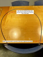
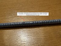
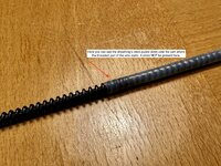
I would like to add a plausible explanation as to why the plastic sheathing on the sunroof motor cable bunches up, as a few of us have reported.

My conclusion is that it is a lack and/or fail of lubrication that causes this.

The plastic sheathing is there to provide a sliding low friction surface between the cable and the outer cable guide tube. When the lubricant fail, either to age (hardens) or just wear (it all bunches up in the bottom of the cable tube), the plastic can slip on the steel wire since the friction is lower there than the unlubricated outer survace, and will start moving independently of the wire.

It can easily catch the wire spiral covering the inner wire, thus bunching it up. The tolerance is quite tight in the tube, but allows for enough space to let this unwanted movement occur. On my cable, the plastic had moved all the way down to the part of the wire where the threaded part starts. Once there, it can't move further since the diameter of the threaded part is larger than the wire part that the sheath covers.

So why doesn't the cable snap and fail, or why was my sunroof working perfectly despite this?

The cable is VERY strong. It is really overkill in the best of ways. The gauge is very thick, it will NOT snap unless it is structurally damaged. The motor is also very strong, and will not stop pulling due to the extra friction provided by the cable plastic being bunched up (to a degree of course).

In the end, the plastic sheathing will fail completely, and bunch up enough to blow the fuse on the motor.

Solutions:

  • Perform the sunroof refurbishment that Joe so excellently detailed in this thread. It is not difficult, does not require any special tools. Your sunroof may be working just fine (as did mine) but have this ticking bomb hidden.
  • Be careful when you extract the cable, the instruction in this How-to is 100% correct, but if the plastic sheathing has bunched up, it will require a lot of force to extract it. Just make sure the motor released it (the motor will not engage when it is released) and pull slowly and carefully out, the goal is to not damage the plastic further.
  • The cable is currently NLA, so if you have a good or new spare, use it.
  • If you don't have a spare, once out, if the plastic is bunched up but not torn, get the cable warm with a heat gun to soften the plastic a little, then pull it carefully to release the bunching.
  • If the plastic is torn, find a good used one.
  • Reinstall following Joe's guide, and for the love of all the Gleit, use it.
Some images:

IMG_8163.jpeg IMG_8162.jpeg IMG_8161.jpeg IMG_8160.jpeg
 
I can't get the cable back, there's a lot of resistance once I've passed the first bend after the cassette. I think the plastic on my cable may be too worn. I'm trying to find a replacement plastic tube, otherwise I'll have to find a new cable. Frustrating...
 
@doolar,
This is just a theory I have no idea how this cable setup looks but could you could possibly take a fine wire and attach it somehow to the cable on the end you are trying to push?

If possible pulling would be much easier than pushing.

First in order for this to work you must be able to insert the fine wire through the opposite end then attach it to the cable and pull it through?

Again, Just a thought:)
 
I believe you can cut a section of the plastic off of the cable. I did this some time ago and although I have a new cable, I haven't replaced it yet. I also believe I read here that the cables did not have the plastic early on. One may be able to remove the entre plastic sheathing.
 
For future reference, I ended up having to remove the pipe that the cable runs in. The grease inside had bunched up. I dissolved it with isopropyl alcohol.

Unfortunately the plastic sheathing was damaged beyond repair, and the sunroof cable is NLA, so I shrink tubed it. 5ft of 8 mm 2:1 shrink tube did the trick. Now the cable runs well into the tubing.

Le gooo:
IMG_8183.jpeg

Shrink tubed:
IMG_8184.jpeg

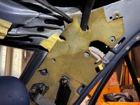
Everything back, it was easier to slice the c-pillar foam and sound deadening to get to the tubing, it sits with two brackets:
IMG_8186.jpeg

I will report back when I’m fully finished.
 
Ok so now I see why the alignment tools are a good idea. They keep the arm bracket in place. Without them it’s a lot more trial and error, but fully doable. I’m almost done with the sunroof now!
 
Can someone provide the calibration procedure to set the lift/stop points of the cable?
The interwebs are chock full of comments but I yet to see an actual MB procedure, specifically how the white dial plays into the process.

I'm assuming this is the same across the 124 platform, but I'm not quite sure of that actually. The one in the wagon has lost it's direction after a cable issue since fixed and I need to reset it.
See the last 2 pages of this FSM PDF... does that help?


:klink:
 
Thanks his helps. But mine has two notches. One is triangular and the other is rounded. Your attached doc isn't clear and I'm assuming it's the rounded one? as it's positioned between the "Heben" and "Senken". Buut wonder what the other is for?
 

Attachments

  • Screenshot 2025-07-26 at 10.18.58 AM.png
    Screenshot 2025-07-26 at 10.18.58 AM.png
    779.4 KB · Views: 5
Last edited:
Back
Top