• Hi Guest !

    Welcome to the 500Eboard forum.

    Since its founding in late 2008, 500Eboard has become the leading resource on the Internet for all things related to the Mercedes-Benz 500E and E500. In recent years, we have also expanded to include the 400E and E420 models, which are directly related to the 500E/E500.

    We invite you to browse and take advantage of the information and resources here on the site. If you find helpful information, please register for full membership, and you'll find even more resources available. Feel free to ask questions, and make liberal use of the "Search" function to find answers.

    We hope you will become an active contributor to the community!

    Sincerely,
    500Eboard Management

HOW-TO: Replacing M119 camshaft oiler tubes

gerryvz

Site Honcho
Staff member
I recently was able to obtain a set of used, but good condition, metal M119 camshaft oiler tubes from a 500Eboard member. I decided to begin the installation procedure and finish it up this coming week as I get the E500 prepared for the trip to MBCA's StarTech meeting in Alabama during the middle of May.

This job overall is not very hard, but it is labour-intensive and requires one to pay attention. It also requires that you have a number of parts on hand, that need to be replaced during the procedure. I would say it would take the average person about 4-5 hours to do this job, perhaps more. I spent three hours alone on the passenger side engine bank, simply because I took my time and cleaned up everything I found.

The following types of tools will be required:
  • various sizes of flat-blade screwdrivers
  • 1/4" and 3/8" ratchets, extensions
  • 11mm socket (1/4 and 3/8" sizes)
  • can or two of brake cleaner
  • 3-4 shop rags
  • flashlight or other strong light source
  • torque wrench
  • 5mm flex-head allen socket
  • 5mm regular allen socket
  • Needle-nose or standard pliers

The following MB parts* are HIGHLY recommended for this job:
  • valve cover gasket kits for left and right side engine banks (MB part numbers 119 010 13 30 and 119 010 14 30)
  • 18 copper "crush" washers for valve cover bolts (MB part number N007603 006106)
  • Replacement metal cam oiler tubes (16)
  • Upper plastic chain rail guides (MB part numbers 119 052 09 16 (two required); 119 050 03 16; and 119 050 02 16)
  • 32 new o-rings for replacement cam oiler tubes (MB part number 015 997 31 48)
*GSXR note: "MB parts" means "Genuine Mercedes" only, not aftermarket, i.e. not Victor valve cover gaskets.


Here's the procedure I followed. The first post will be for the passenger side of the engine. The second post will be for the driver's side. It's also a good idea to replace the spark plugs when you are doing this job; they are rarely so accessible. If you have more than 20K miles on your plugs, you should plan to do the plugs.

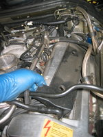
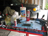
First of all, a view of the engine as the hood is opened, and with the air intake "zoom" tubes, air box and plastic vanity panel removed.
IMG_2442.JPG IMG_2443.JPG


If anyone is interested, here's the solenoid setup for the nitrous-oxide injection system, that sits on the inner firewall just behind the airbox.
IMG_2444.JPG


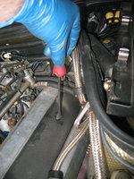
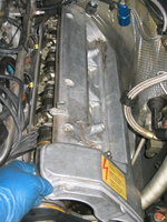
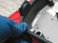
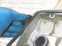
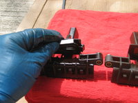
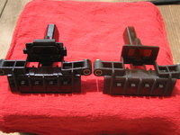
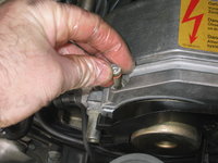
Next up is to remove the plastic panel that covers the distributor and cam advance solenoid. This just unclips and lifts off. Then, it's time to take a large flat-blade screwdriver, and remove the two plastic bolts that hold the ignition and spark plug wire cover to the aluminum valve covers. Photos 3 and 4 below show the plastic cover coming off, and what's underneath it.
IMG_2445.JPG IMG_2446.JPG IMG_2447.jpg IMG_2448.JPG


The next step is to remove these two wiring bundles from their secured point to the top of the valve cover. The flat metal plate holds them to the valve cover, and the plate is attached by two 5mm allen head bolts, which are removed with ease. Note that one bolt is longer than the other. The longer bolt goes on the side toward the passenger compartment (firewall) - something to remember at re-assembly time.
IMG_2449.JPG IMG_2450.JPG IMG_2451.jpg IMG_2452.jpg IMG_2453.JPG


For future reference, here's how the ignition wires are routed to the passenger-side engine bank.
IMG_2456.JPG IMG_2455.jpg


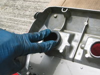
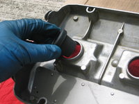
Then it's time to remove the spark plug connectors, and the breather hose at the bank of the valve cover. The clamp can be squeezed together with a pair of needle nose or channel-lock pliers to release it, and then the hose can just be twisted off the fitting.
IMG_2457.JPG IMG_2458.jpg


I also took the time to remove the two 5mm allen bolts that held the black plastic wire routing piece atop the cylinder head. I move then back a couple of inches toward the MAF, as shown. This was to provide more clearance/room for the next steps.
IMG_2454.JPG


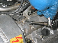
Here begins the process of removing the nine valve cover bolts. The pivoting-head 5mm 1/4" socket came in extremely handy for both the front and rear corner bolts, which would have been EXTREMELY difficult to remove otherwise. This tool is almost imperative for the job. Make sure you get it before you remove the valve covers.
IMG_2459.jpg IMG_2460.jpg IMG_2461.jpg IMG_2462.jpg IMG_2463.jpg IMG_2464.jpg IMG_2465.jpg


Here's the bolts, laid out in the correct order on my work table. Notice that the middle bolt at the front of the motor is longer than the others.
IMG_2466.JPG


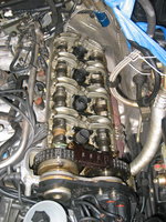
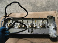
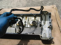
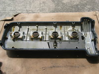
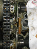
Then, I pried loose the cam cover with a large flat-blade screwdriver and carefully removed it from the top of the cylinder head. Notice that three of the four spark plug boots stayed attached to the head, not the valve cover. These boots will be pried off and removed later. All of this rubber (boots and the valve cover gasket) was quite hard - not petrified, but very close to being rather brittle.

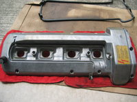
Also included are a couple of photos of the removed valve cover, and the valvetrain immediately after the cover was removed. Notice it's quite clean in there, as a result of using synthetic motor oil !!
IMG_2467.jpg IMG_2468.JPG IMG_2469.JPG


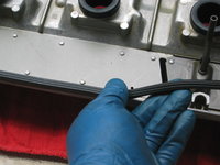
Here's a close-up of the brown plastic timing chain top slide rail.
IMG_2470.jpg


Next, I covered the exposed area of the motor with clean rags so that it would be rather protected from airborne pollen, dust and other contaminants.
IMG_2471.jpg


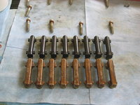
Here are the 16 replacement cam oiler tubes lined up on my work table, ready for replacement. All of the tubes have new, green, MB factory o-rings installed. This is highly advisable to do as a precaution, as older/used sets of oiler tubes will have used rubber o-rings, which can be brittle and/or petrified. I found this exactly to be the case when I removed the old rubber o-rings that came on the oiler tubes. They were quite rigid and fairly brittle.
IMG_2472.JPG IMG_2473.jpg


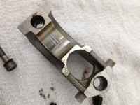
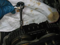
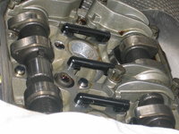
Next step is to begin removing the cam bearing caps, two at a time (one for the intake cam, the other for the exhaust cam. For three of the five towers, you will replace two cam oiler tubes when you remove the pair of bearing caps. DO NOT MIX UP THE CAPS WHEN YOU REMOVE THEM -- KEEP THEM IN THE ORDER AND ASSOCIATED WITH THE CAM THEY CAME OFF OF. The cam bearings are held on by two 11mm bolts, which are re-torqued to 10 Nm when re-installed. For the frontmost and rear-most cam bearing caps, you will only replace ONE tube each. The front-most tube also requires replacement of the plastic slide rail assembly, which will be shown a bit later.
IMG_2474.jpg IMG_2475.JPG IMG_2476.JPG IMG_2477.JPG


Here is a detailed comparison of the plastic vs. metal oiler tubes. Notice that my stock plastic tubes also came from the factory with green o-rings.
IMG_2478.JPG IMG_2479.JPG IMG_2480.JPG IMG_2481.JPG


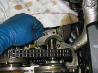
Here are a few views of installing the new oiler tubes into place .... fitting them and pressing them down with a "click"
IMG_2482.JPG IMG_2483.JPG IMG_2489.JPG


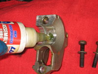
After fitting the tube(s) in place, it's time to replace that pair of cam bearing caps. Because I'm rather anal, I cleaned off the bearing surface with a rag, and then added a small dollop of assembly lube that I'd initially used on my M117 rebuild several years back, for exactly the same purpose -- to provide some initial lubrication at startup, until proper oil pressure can be built up and the oil circulates properly through the valvetrain.
IMG_2485.JPG IMG_2484.JPG IMG_2490.JPG
 
Last edited:
The next step is super-important and delicate ... the removal and replacement of the plastic sliding rail for the top of the timing chain, located between the cam sprockets. This plastic rail consists of two plastic pieces (which are rather inexpensive) that press together and are locked by six small tangs, which snap into slots. It's fairly self-explanatory once you see it. I used a couple of small flat-blade screwdrivers to release the tangs. It's a GREAT idea to place rags below the sprockets and plastic slide rail area, because you WILL break some of the tangs off in the process, and you don't want to lose these pieces of plastic down into the motor. As you can see from the photo, I broke off quite a few pieces and was able to capture them. This plastic is quite old and brittle, and is subjected to quite a lot of heat and abuse, so it's IMPORTANT that you purchase new plastic rails BEFORE you do this job. Part numbers are above. Trust me, you WILL break the plastic in the process of removing it, unless it is brand new or near new.

The large piece is held on with two 5mm allen bolts.
IMG_2492.jpg IMG_2491.jpg IMG_2493.JPG IMG_2494.JPG


You can see the difference between the old (right, dark brown plastic) and new (left, lighter brown plastic) guide pieces.
IMG_2496.JPG


Also, notice on the older piece that there is a square rubber piece. This piece should be transferred over from the older guide piece to the newer piece. This can be accomplished in just seconds.
IMG_2497.JPG IMG_2497.JPG IMG_2498.JPG


Here I am fitting the two plastic pieces into place around the timing chain, and locking the upper and lower tangs (there are 6 tangs in total .. four on the top side and two on the underside.
IMG_2499.JPG IMG_2500.JPG IMG_2501.JPG


Last up was the rear bearing caps, which had to be removed so that the last tube could be replaced. I used a coat hanger to secure the wiring bundles and hoses so they were out of the way, and I could get a "bite" on the cam bearing bolts with my 11mm socket.
IMG_2502.JPG


After successfully replacing the last of the eight oiler tubes on that side, I turned my attention to prying off and removing the oil-baked-on spark plug boots. Two photos here, removing the boot, and what the cylinder head looks like with the boot removed, between two replaced cam oiler tubes. You can see the seating surface for the spark plug boot; I cleaned these off with a brake-cleaner-soaked rag.
IMG_2503.JPG IMG_2504.JPG IMG_2495.JPG


After that, I was pretty much done with the cylinder head side of things. It was time to turn my attention toward the valve cover. First, I removed the near-petrified valve cover gasket, and then cleaned EVERYTHING off (particularly on the outside of the cover) with brake cleaner to get off all the dirt and grime in the crevasses.
IMG_2505.JPG IMG_2506.JPG IMG_2507.JPG


The next step was to install the new valve cover gasket, which went on seamlessly and quite easily. I then installed the four new spark plug boots that came in the kit.
IMG_2508.JPG IMG_2509.JPG IMG_2510.JPG


Here are a few photos of the boxes that the valve cover/spark plug boot kits came in, along with the part number and inscription on the side of one of the spark plug boots.
IMG_2511.JPG IMG_2512.JPG IMG_2513.JPG IMG_2514.JPG


And finally, two views of the cleaned and completed valve cover, ready for re-installation back onto the passenger side cylinder head. Assembly is exactly the reverse of removal.....
IMG_2515.JPG IMG_2516.JPG
 
Last edited:
Great writeup. The factory gaskets make it so much easier to install the valve covers. They fit like a glove.
 
As usual great write up..You're on the roll, Mr bigpants ! :-D Why did you change tubes? Were you hearing the classic tick noise?

:thumbsup2:
 
Can't wait to get started on this job. Thanks for the detailed write up with pictures Gerry!
 
Why did you change tubes? Were you hearing the classic tick noise?
I did hear a slight/modest ticking from the driver's side when I was testing the car after doing the tandem pump. The passenger side sounded fine. It was enough to push me over the edge of doing this job, seeing as I had the metal tubes in hand ... no time like the present.

By the way, the passenger side oiler tubes were all in good condition on my car -- none of them were popped. I am going to keep the removed tubes in case I have an urgent, future need for a replacement tube.

Of course, so many other jobs to do. The Houston spring window for working on cars (i.e. modest heat and humidity) is fast slamming shut; we've had a surprisingly cold/mild spring so far, but this can/will end any day now....pretty much living on borrowed time until the deluge of summer heat. Turned our A/C on in the house and it's pretty much going to be on 24/7 through Halloween.

Cheers,
Gerry
 
Awesome writeup! Questions / comments:

1) You may want to note in your parts list that OE/Genuine valve cover gaskets are strongly recommended

2) You may want to note in your parts list that depending on their age, the PCV hoses may break during valve cover removal, and list (or link to) the part numbers

3) The valve cover bolt seat should be cleaned prior to re-installing, and all bolts should be torqued to spec at 9Nm, where a torque wrench will fit (all but lower/rear bolt)

4) You may want to clarify that after each cam bearing pair is removed, these MUST be re-installed and torqued before moving on to the next pair

5) Did you find any "popped" plastic oil tubes on the driver's side, or were they all still OK?


:watchdrama:
 
Awesome writeup! Questions / comments:

1) You may want to note in your parts list that OE/Genuine valve cover gaskets are strongly recommended
Yes ...listed in there from the get-go, including part numbers

2) You may want to note in your parts list that depending on their age, the PCV hoses may break during valve cover removal, and list (or link to) the part numbers
Will add this as a separate post.

3) The valve cover bolt seat should be cleaned prior to re-installing, and all bolts should be torqued to spec at 9Nm, where a torque wrench will fit (all but lower/rear bolt)
This is part of the valve cover cleaning process; brake cleaner was sprayed onto all bolt holes and the area thoroughly cleaned with a rag to remove dirt/debris.

4) You may want to clarify that after each cam bearing pair is removed, these MUST be re-installed and torqued before moving on to the next pair
I guess I may not have been explicit enough here ... so your clarification is good here. To reiterate -- ONLY remove one pair of cam bearing caps at a time. After replacing the oil tube(s), re-install and re-torque both caps before moving onto the next pair of cam bearing caps. This is IMPERATIVE.

5) Did you find any "popped" plastic oil tubes on the driver's side, or were they all still OK?
Don't know; haven't done driver's side yet. Only had time in the afternoon for passenger side work. Will git 'r done this week.

:lightning:
 
One thing I forgot to mention is that when you put the cam covers back on the car after doing the job, be VERY careful to ensure that the cam cover gasket remains in place on the cover itself. It's such a tight squeeze between the back of the cylinder head and the firewall, that when you are putting the cover back on it is very easy to accidentally shift it out of place or off the end of the cover and not even know it!!

The best thing to do is know that it will take at least 2-3 times to get it right, so have patience. You will need to also run your fingers around the end of the valve cover once it is fit into place (bare fingers work best here) to make sure it is in the proper position.

Again ... take your time and have patience! It took me 5 or 6 tries to get it on where I was very sure that all was where it was supposed to be.

Also ... Don't torque the cover bolts down hard! Spec is 8 Nm and that is NOT very tight.

Cheers,
Gerry


Sent from my iPad using Tapatalk HD
 
Folks ... stop the presses. Please disregard this full DIY, as the critical torque spec I mentioned for the cam cover is 1 Nm off.

Sincere apologies for the error.

I'll be deleting this DIY soon for reasons of gross inaccuracy.:run:
 
'Tis refreshing to see someone taking 'sponsitility for their actions. Jolly good show, ol' chap!!

:clapper:
 
I have just read thru the whole thread and i must say WOW!! Exactly what i needed. I can´t wait to start changing them.

No i just have another mather. Should i put these babies in my 420 or should i wait for my future 500...? ;)

And again: Thanks Gerryvz for this amazing thread and thank all on this forum for all the valuable knowledge! :)
 
This is the second half of the M119 cam oiler tube DIY -- this time for the left (driver's side) bank of cylinders.

This job (while fundamentally the same as the passenger side) is different because you have a vacuum line and a fuel line to deal with. To handle these, you will need a 17mm and a 19mm open end wrench for these two lines.

The driver's side has a bit more clearance between the back corner of the cylinder head and the inner firewall. This makes it a bit easier to get a hand in there to insert sockets, remove loosened cam cover bolts, and so forth. It's easier on the driver's side than the passenger side, for sure.

So, let's get into the job. First of all, a view of my roll-around work table, with the tools of the trade on it. Because it was about 82 degrees today, a large soda was definitely de rigeur. Then, a view of the left bank of the engine, before touching anything.
View attachment 17566 View attachment 17499


As before, the next step is to remove the two large plastic screws that hold the spark plug and wire cover to the cam cover. Then, carefully lift off the cover. Put it aside for cleaning later.
View attachment 17500 View attachment 17501 View attachment 17502 View attachment 17503


Here's the spark plug and wire compartment, exposed. Pull the spark plug connectors out and bend them over the intake system, to get them out of the way.
View attachment 17504


Next up, use a set of pliers (I used bent-needlenose here) to squeeze the clamp holding the breather hose onto the cam cover. Sometimes you can remove it by hand if you pull up hard enough. Note that these hoses can be fossilized from heat and age, and are easily broken. I had replaced all vacuum and rubber hoses attached to the top end of the motor when I lived in Portland some years back, so my hoses are all in excellent, non-petrified condition....
View attachment 17505 View attachment 17506


Then you can carefully bend the breather hose back, swiveling it on its built-in joint. It twists out of the way nicely and very easily. Then remove the plastic cover for the distributor cap and rotor. A quick check of the area underneath the power steering reservoir shows no leakage since my recent tandem pump rebuild/short hose replacement. :wahoo:
View attachment 17507 View attachment 17508 View attachment 17509 View attachment 17510


Next step is the vacuum line that goes over and across the top of the cam cover. a 19mm open-wrench (I also counter-held it with a 17mm) dispatched that connector quickly.
View attachment 17511 View attachment 17512


And after that, you have to remove the fuel line that goes from the fuel cooler to the fuel rail, joining at the base of the fuel pressure regulator. Again, your 17mm open-end wrench makes quick work of loosening that joint. You will want to have a rag underneath it to catch any fuel that dribbles out (there will be a little). You can minimize fuel spill if you just quickly tilt the hose upward after loosening the connector.
View attachment 17513 View attachment 17514


After you have those items removed, you can then begin to attack the cam cover removal process itself. Loosen each of the 9 bolts that hold it on. Remember when you remove the bolts, to make sure you get the copper washers too.
View attachment 17515 View attachment 17516 View attachment 17517 View attachment 17518 View attachment 17519


Here is a view of the eight metal cam oiler tubes on my work-table, lined up next to the eight plastic ones that I removed from the right bank of the engine.
View attachment 17520


And here's a notable photo. A new cam cover copper washer on the left, compared with two "used" ones removed from cam cover bolts. Note the concave (dished) appearance of one due to the bolt head, and the lip that formed on the underside of the other one due to it being pressed into the hole on the cam cover. These shapes and deformations are why new copper washers are REQUIRED at each cam cover removal.
View attachment 17521


To give myself a little more access for cam cover removal and re-installation, I also loosened the bracket that holds the nitrous solenoids to the inner firewall, and lifted the bracket with solenoids attached by an inch or two. This was of immense help but won't apply to 99% of y'all doing this job. You can also see that I swiveled and lifted up the other fuel line so that it was above the area and totally out of the way.
View attachment 17522


And now, the cam cover is pried off and then carefully remove from the cylinder head. And here are some shots of the valvetrain and the inside of the cam cover, immediately after removal.
View attachment 17523 View attachment 17524 View attachment 17525


A thorough cleaning of the cam cover is next up, after first removing the old gasket. Chlorinated (49-state) brake cleaner works a great number for this.
View attachment 17526 View attachment 17527 View attachment 17528


A couple of photos of the cam cover after cleaning. Doesn't have to be spotless, but all of the dirt and sealing surfaces have to be cleaned well, including the spark plug wells.
View attachment 17529 View attachment 17530


Now that things are clean, it's time to press the new spark plug boots that came with the gasket kit into place, and carefully install the new cam cover gasket.
View attachment 17531 View attachment 17532 View attachment 17533 View attachment 17534 View attachment 17535 View attachment 17536


And ... here is the "fully loaded" cam cover, ready for re-installation. Set it aside, as you'll be needing it soon.
View attachment 17537
 

Attachments

  • IMG_2526.JPG
    IMG_2526.JPG
    627.6 KB · Views: 20
  • IMG_2525.jpg
    IMG_2525.jpg
    773.5 KB · Views: 20
  • IMG_2524.jpg
    IMG_2524.jpg
    780.3 KB · Views: 22
  • IMG_2523.jpg
    IMG_2523.jpg
    678.5 KB · Views: 22
  • IMG_2522.JPG
    IMG_2522.JPG
    607.3 KB · Views: 22
  • IMG_2521.jpg
    IMG_2521.jpg
    812.2 KB · Views: 25
  • IMG_2536.JPG
    IMG_2536.JPG
    613.5 KB · Views: 20
  • IMG_2535.jpg
    IMG_2535.jpg
    752 KB · Views: 21
  • IMG_2534.JPG
    IMG_2534.JPG
    496.9 KB · Views: 22
  • IMG_2533.JPG
    IMG_2533.JPG
    540.4 KB · Views: 22
  • IMG_2532.jpg
    IMG_2532.jpg
    610.1 KB · Views: 23
  • IMG_2531.JPG
    IMG_2531.JPG
    598.2 KB · Views: 21
  • IMG_2530.JPG
    IMG_2530.JPG
    468 KB · Views: 21
  • IMG_2529.JPG
    IMG_2529.JPG
    595.1 KB · Views: 22
  • IMG_2528.jpg
    IMG_2528.jpg
    655.4 KB · Views: 22
  • IMG_2527.jpg
    IMG_2527.jpg
    683.4 KB · Views: 20
  • IMG_2544.JPG
    IMG_2544.JPG
    353.1 KB · Views: 20
  • IMG_2547.jpg
    IMG_2547.jpg
    770.8 KB · Views: 22
  • IMG_2548.jpg
    IMG_2548.jpg
    802.3 KB · Views: 21
  • IMG_2549.JPG
    IMG_2549.JPG
    835.8 KB · Views: 21
  • IMG_2542.JPG
    IMG_2542.JPG
    540.9 KB · Views: 21
  • IMG_2541.JPG
    IMG_2541.JPG
    380.8 KB · Views: 10
  • IMG_2540.JPG
    IMG_2540.JPG
    513 KB · Views: 19
  • IMG_2539.JPG
    IMG_2539.JPG
    567.5 KB · Views: 20
  • IMG_2538.JPG
    IMG_2538.JPG
    501.5 KB · Views: 20
  • IMG_2537.JPG
    IMG_2537.JPG
    536.3 KB · Views: 22
  • IMG_2555.JPG
    IMG_2555.JPG
    602.4 KB · Views: 18
  • IMG_2554.JPG
    IMG_2554.JPG
    583.4 KB · Views: 17
  • IMG_2553.JPG
    IMG_2553.JPG
    523.6 KB · Views: 18
  • IMG_2552.JPG
    IMG_2552.JPG
    641.3 KB · Views: 16
  • IMG_2551.JPG
    IMG_2551.JPG
    589.2 KB · Views: 16
  • IMG_2550.JPG
    IMG_2550.JPG
    648.8 KB · Views: 19
  • IMG_2561.JPG
    IMG_2561.JPG
    417 KB · Views: 18
  • IMG_2560.JPG
    IMG_2560.JPG
    468.5 KB · Views: 16
  • IMG_2559.JPG
    IMG_2559.JPG
    296.6 KB · Views: 16
  • IMG_2558.JPG
    IMG_2558.JPG
    427.7 KB · Views: 15
  • IMG_2557.JPG
    IMG_2557.JPG
    496.2 KB · Views: 15
  • IMG_2556.JPG
    IMG_2556.JPG
    476.7 KB · Views: 16
  • IMG_2562.JPG
    IMG_2562.JPG
    598.7 KB · Views: 20
  • IMG_2520.JPG
    IMG_2520.JPG
    569.2 KB · Views: 27
Next up is the removal of the timing chain upper guide/retainer. Same exact process as the passenger side, although the part is slightly different it's of a very similar design. I used small flat-blade screwdrivers to loosen the clips. Again, BE SURE not to get pieces of plastic in the engine if you can help it.
View attachment 17567 View attachment 17568 View attachment 17569 View attachment 17570 View attachment 17571 View attachment 17572 View attachment 17573 View attachment 17574 View attachment 17575


Now, it's time for the actual open heart surgery ... oiler tube replacement. Again, and this is IMPERATIVE. ONLY remove one pair of cam bearing caps at a time (a vertical pair), and replace/re-torque them down immediately after oiler tube replacement before moving onto the next pair.
View attachment 17576 View attachment 17577 View attachment 17578 View attachment 17579


When you re-install the cam bearing caps, it's an excellent idea to clean them with a lint-free rag or cloth, and then apply a few drops of assembly lube before re-fitting them onto the cylinder head and re-torquing them.
View attachment 17580 View attachment 17581 View attachment 17582 View attachment 17583 View attachment 17584


Next up, it's time to re-install the timing chain retainers, if you haven't done that yet. You must remove them to remove the cam bearing caps (and thus the two oiler tubes) that are closest to the timing chain sprockets (front of the car).
View attachment 17585 View attachment 17586 View attachment 17587


And here's the installation process for the cam cover. Notice the photo with my fingertips, where I'm "feeling" for the seated gasket at the rear corner between the head and firewall. It took me 9 tries to get this right, but I finally did. My advice is to feel with your bare fingertips what it feels like while the cam cover is out of the car, with the gasket installed. Then you will know what it feels like when installed. If it feels different .. pull it and try again. It takes a bit of patience and you should take a break if you get frustrated.
View attachment 17588 View attachment 17589 View attachment 17590


After the cam cover is installed, you can put the new washers on the 9 cam cover bolts and re-insert and torque them down.

NOTE: GSXR will remind me that they should be torqued to 9 Nm, so do not forget this !!! For the bottom corner bolt, I used a magnetic extender to insert the bolt into the hole in the cam cover/head, and then did the same thing again to insert the 5mm swivel hex socket into the hole in the bolt head. Worked well.
View attachment 17591 View attachment 17592


And, after everything is double-checked and torqued down ... a couple of views of the completed engine in the afternoon Houston sunlight.
View attachment 17593 View attachment 17594


I hope this process helps anyone in the future who is looking to do this job.

Total time for the driver's side is perhaps 2-3 hours. It goes faster the second time around.

Cheers,
Gerry
 

Attachments

  • IMG_2569.JPG
    IMG_2569.JPG
    456.1 KB · Views: 11
  • IMG_2570.JPG
    IMG_2570.JPG
    424.5 KB · Views: 10
  • IMG_2571.JPG
    IMG_2571.JPG
    457.1 KB · Views: 9
  • IMG_2572.JPG
    IMG_2572.JPG
    595.6 KB · Views: 11
  • IMG_2568.jpg
    IMG_2568.jpg
    681.7 KB · Views: 9
  • IMG_2567.JPG
    IMG_2567.JPG
    526 KB · Views: 11
  • IMG_2566.JPG
    IMG_2566.JPG
    606.6 KB · Views: 10
  • IMG_2565.JPG
    IMG_2565.JPG
    410 KB · Views: 13
  • IMG_2564.JPG
    IMG_2564.JPG
    593.4 KB · Views: 14
  • IMG_2563.JPG
    IMG_2563.JPG
    415.5 KB · Views: 13
  • IMG_2579.jpg
    IMG_2579.jpg
    760.7 KB · Views: 9
  • IMG_2580.JPG
    IMG_2580.JPG
    570.8 KB · Views: 10
  • IMG_2581.JPG
    IMG_2581.JPG
    581.4 KB · Views: 10
  • IMG_2582.jpg
    IMG_2582.jpg
    709.6 KB · Views: 9
  • IMG_2578.JPG
    IMG_2578.JPG
    546.2 KB · Views: 10
  • IMG_2577.JPG
    IMG_2577.JPG
    631.4 KB · Views: 9
  • IMG_2576.JPG
    IMG_2576.JPG
    385.4 KB · Views: 10
  • IMG_2575.JPG
    IMG_2575.JPG
    501 KB · Views: 10
  • IMG_2574.JPG
    IMG_2574.JPG
    491.3 KB · Views: 11
  • IMG_2573.jpg
    IMG_2573.jpg
    713.9 KB · Views: 9
  • IMG_2591.JPG
    IMG_2591.JPG
    532 KB · Views: 12
  • IMG_2590.JPG
    IMG_2590.JPG
    509.1 KB · Views: 13
  • IMG_2589.jpg
    IMG_2589.jpg
    608.1 KB · Views: 11
  • IMG_2588.JPG
    IMG_2588.JPG
    428.5 KB · Views: 9
  • IMG_2587.JPG
    IMG_2587.JPG
    398.3 KB · Views: 10
  • IMG_2586.jpg
    IMG_2586.jpg
    654.2 KB · Views: 9
  • IMG_2585.JPG
    IMG_2585.JPG
    669.6 KB · Views: 10
  • IMG_2583.jpg
    IMG_2583.jpg
    808 KB · Views: 9
Holy crap, Gerry. I envy you. Wish I could (and would dare to) do that.

Very interesting material!!
 
:texasflag:This will have to wait until after Startech, but you make doing work on my car a joy BECAUSE of the detailed pictures and instructions.

Many thanks Gerry!
 
Another great "how to", Gerry. Make sure to give it a proper shakedown. I'm looking forward to meeting you and seeing your nitrous-juiced E500 this weekend.

drew
 
The car got a shakedown this morning on the 20-mile drive to work. All seems good. I'm going to replace the center link and idler arm bushings this week and get it aligned, and should be good to go for the run to Alabama.

I'm leaving very late on Friday night and driving all night to get to Alabama, but will be there bright and early on Saturday AM. Will be leaving on Tuesday AM early.

Cheers,
Gerry
 
Hi guys,
I am painstakingly removing the old o-rings on the oil tubes and replacing them with new o-rings. Any tricks of the trade are welcome as I am currently using a needle.
Also, Autohaus AZ sent me the Victor valve cover gaskets. I see that you don't want to use those. Where do I order OE Mercedes?
 
Here is what I found on parts.com:

[TABLE="align: center"] [TR] [TD="colspan: 5"]1993 - MERCEDES-BENZ - 500E - - V8 - 5.0L - GAS[/TD] [/TR] [TR] [TD="colspan: 5"] ENGINE / CYLINDER HEAD & VALVES / CYLINDER HEAD & VALVES / VALVE COVER GASKET [/TD] [/TR] [TR] [TD] 1190101330 - VALVE COVER GASKET 4.2L, 5.0L; Left 8 CYLINDER, 4.2L & 5.0L D.O.H.C.

[/TD] [TD="width: 80, align: center"]MSRP[/TD] [TD="width: 80, align: center"]Core[/TD] [TD="class: savings, width: 80, align: center"]Save[/TD] [TD="width: 100, align: center"]Online Price[/TD] [/TR] [TR] [TD="width: 80, align: center"]$42.00[/TD] [TD="width: 80, align: center"]$0.00[/TD] [TD="class: savings, width: 80, align: center"]$12.00[/TD] [TD="width: 100, align: center"]$30.00[/TD] [/TR] [/TABLE]
 
I found that I was able to "stab" the o-ring with a small bobby pin, then slide a small flat head screw driver to get the o-rings off. All 32 of them came off in about 20 minutes.
 
Yes, I used a small, flat-blade jeweler's screwdriver (same that you would use to tighten eyeglasses) to remove the o-rings. Splitting them helps as you are not going to use them anymore.

DO NOT get aftermarket valve cover gaskets. Return what you had. Just get the OE / MB gaskets. They are a PERFECT fit on the valve covers. Aftermarket rubber is just not worth it, even if it's an OEM for other MB parts. Just get the factory gaskets, they are not much more money than the aftermarket. The factory gaskets also include the spark plug rubber boots that press onto the valve cover for that side of the engine.

I think I listed the part numbers (and definitely showed photos of the boxes) in the how-to for the factory valve cover gaskets.

I will be leaving late Friday night for Alabama and driving all night, arriving Saturday morning at StarTech. I will probably end up pulling over along the way and napping for an hour or two. Will be leaving on Tuesday morning to drive back home. Definitely looking forward to it and to meeting a few 500Eboarders to add to the list of folks I've met in person.
 
I will probably end up pulling over along the way and napping for an hour or two.

The Mississippi welcome center is a perfect place for that. Relatively new & immaculately clean. I powernapped there for a couple hours during my cross-country trip in the 500E.
 
Aye, They do Southern hospitality right in the MS rest areas. We experienced this during our family vacation in Tennesee, coming home through MS.

Along the way back to TX, I'll be stopping to see the small town in MS where I lives age 1-6, only the second time I will have been back since we moved back to Seattle in 1973.
 
Roger that! I am sending the Victors back to Autohaus AZ and my new original MB valve covers will be in tomorrow.
 
I would like to jump in here with some real controversy: oil. Gerry, you mentioned synthetic oil; my favorite. And my favorite brand and weight is Mobil1, 10/40. Your engine sure does look clean. So does my wife's 2002 Passat 4motion. It has 162K on the clock. Last fall there was a valve cover leak on both heads (V6). When I removed the valve covers I was amazed at the engines cleanliness. After all these years I have done an oil change only twice since new on her car. The initial change was made from factory oil to Mobil1 after break-in. After routine filter changes twice a year, the oil was changed at 100K. It was changed again at 136k because my wife wanted all new oil. You got to love today's chemistry.

Thank you for the write up too. Will it be available as a download?
 
So does my wife's 2002 Passat 4motion. It has 162K on the clock. After all these years I have done an oil change only twice since new on her car. The initial change was made from factory oil to Mobil1 after break-in. After routine filter changes twice a year, the oil was changed at 100K. It was changed again at 136k because my wife wanted all new oil. You got to love today's chemistry.
9elf, I wouldn't try that with the current formula of Mobil-1. They cheaped out and went to a Group III base stock somewhere around 2006-2007. With the current formula, you'll probably have to add a lot of makeup oil after 10k or so. I also hope you were getting oil analysis done periodically... if not, you're taking a pretty major risk. Analysis is cheap insurance if you like extended drains. Make sure you get TBN analysis, most places charge extra for this, but it's a critical data point.

:wormhole:
 
I have been using the Mobil 1 TDT (Turbo Diesel Truck) oil for the past 4-5 years, and IIRC I was using the black-label "European Car Formula" oil before that. I change this oil every 5,000 miles with these Group III partial synthetics, and have had no problems with consumption, etc.

My M117s use the 20W/50 Brad Penn oil, which they call "semi-synthetic" but is really an extremely high quality crude "dino" oil that is from Pennsylvania. The Brad Penn is changed every 3,000 miles.

It was apparent from the color of the oiler tubes (brown varnish) that conventional "dino" oil had been used in the engine in which they were originally installed. It will be interesting to see how long it takes for the detergency of the Mobil I synthetic to clean them to their natural state...

As far as making the how-to available as a download ... I'd recommend just saving each of the "pages" of the HOW-TO as a PDF file.

Cheers,
Gerry
 
Should I also return Part#s 119 052 09 16 (timing chain guide/rails, outer guide clip on)? These are Febi parts, although they are stamped "Germany" in the plastic.
Or, are they OK to use?
 
Personally, for a critical part like a timing chain guide, I would ONLY go factory. I don't trust Febi more than I can throw it.
 
Ok, the Febis are going back with the Victors. I'll order the MB OE.
Thanks, Gerry
 
Great write up! I'm planning on doing my VCG and the oiler tubes very soon. I have a 1992 400E built July 1992. How do I tell if I have the plastic or metal oilers? I opened my oil filler cap and checked the nearest oiler. It's black and when I tapped it with a screwdriver, it did not ping like metal. It felt like plastic and I was able to lightly gouge it with the tip of the screwdriver. I'm guessing I have the plastic? As far as aluminum replacements go, how are the Rauch & Spiegel?

And where did you buy the 5mm flex head hex socket?
Be sure you go with the factory valve cover gaskets.

Generally you can tell by your VIN if you have metal or plastic oilers. GSXR can likely help you with this as he is an 034 and 036 owner. You will need to look with a flashlight in your oil filler tube.


The aluminum replacements are quite expensive, but they are new and they are available. You can also try to get a used set of the factory metal tubes (which is what I did). They come up for sale here pretty regularly with various folks.

The 5mm swivel socket is available via Amazon.com. It's made by an Asian company called VIM, but is of very high quality. There is more information about this at this thread. It's money well spent.

Cheers,
Gerry
 
There is no VIN break, and no date break. Most 1992 models have metal oil tubes, but some late builds may have plastic. (Most 93 have plastic, but some early builds may have metal.) July 1992 is a late-build 1992 model year so it could have plastic tubes. More info is here.

The difference is very obvious visually, plastic are black, metal are gray/brown aluminum colored, as shown in Gerry's photos:

View attachment 17231

:banana1:
 
Is the same true with the 034 in terms of late 1992s going to plastic tubes, same as the 500E? I didn't want to make that automatic assumption.
 
Is the same true with the 034 in terms of late 1992s going to plastic tubes, same as the 500E? I didn't want to make that automatic assumption.
Yes - AFAIK, it was for all M119's produced in the 1992 time frame (which would be 1992-1993 USA model years).

:mushroom1:
 
Thanks for the replies. I have a feeling I've got the plastic tubes with the information mentioned above. The one that I was able to see still looked good but at 181,000 miles, I think it's time to replace. I was just planning on the valve cover gaskets but if taking the valve covers off I might as well replace a bunch of other stuff. I'm ordering the parts soon. Never worked on a Mercedes before so if I get stuck somewhere I'll be asking some questions.
 
Hi guys,
I just finished doing the passenger side and would like to comment about this job.

1. My breather hose clamp at the back of the valve cover was turned the wrong direction, so I ended up just pulling it off.
2. The pivoting-head 5mm 1/4" socket came in extremely handy for both the front and rear corner bolts, which would have been EXTREMELY difficult to remove otherwise. This tool is almost imperative for the job. Make sure you get it before you remove the valve covers.
THIS IS AN UNDERSTATEMENT. IT IS IMPERATIVE! The one on the back (by the firewall) was very difficult to remove.
3. My plastic sliding rail did indeed break, but luckily, we have this write up to help us think ahead.
I retrieved the broken plastic from the rags underneath, so none fell into the engine.
4. I did not know the re-torque settings for my cam bearing caps. Gave it a good guess of 15lbs.
5. Put everything back together, and so far, no leaks!

Will do the driver's side next, as I would not want to do anything out of sequence. . .:bat:

Thanks for the excellent instructions Gerry!
 
4. I did not know the re-torque settings for my cam bearing caps. Gave it a good guess of 15lbs.

The cam bearings are held on by two 11mm bolts, which are re-torqued to 10 Nm when re-installed.

(From GVZ's original post, above.)

I don't know if 5 nm would make a difference here.
 
Well,
I messed up and missed that.
Do you think I'll be OK with 20nm, or should I take it all apart and re-torque to 10nm?
Is there possible harm if I leave it at 20nm?
 
I also just finished my passenger side:


Hi guys,
I just finished doing the passenger side and would like to comment about this job.

1. My breather hose clamp at the back of the valve cover was turned the wrong direction, so I ended up just pulling it off. Mine was too and the hose clamp was impossible to remove so I ended up cutting the hose off. I have a replacement hose so it's no big deal. The other hose that goes to the throttle body would be nice to replace. I heard it is difficult?
2. The pivoting-head 5mm 1/4" socket came in extremely handy for both the front and rear corner bolts, which would have been EXTREMELY difficult to remove otherwise. This tool is almost imperative for the job. Make sure you get it before you remove the valve covers.
THIS IS AN UNDERSTATEMENT. IT IS IMPERATIVE! The one on the back (by the firewall) was very difficult to remove. Ditto this. Get the right tool before you tackle this job! The rear bolt is not too difficult with the right pivoting hex socket.
3. My plastic sliding rail did indeed break, but luckily, we have this write up to help us think ahead. Mine was still in very good shape. But I had a replacement along with the gasket. It's a very cheap part so I'd recommend changing.
I retrieved the broken plastic from the rags underneath, so none fell into the engine.
4. I did not know the re-torque settings for my cam bearing caps. Gave it a good guess of 15lbs. Service manual calls for 10Nm, in ft/lbs that's about 7.5 ft/lbs
5. Put everything back together, and so far, no leaks! Feels good to get this job done!

Will do the driver's side next, as I would not want to do anything out of sequence. . .:bat:

Thanks for the excellent instructions Gerry!
Overall this was not too difficult of a job thanks to the great perfect write up!
 
Just finished the driver's side oil tubes today. No real problems this time.
Still used a little more than 10nm for the cam bearing caps. I cannot believe that the manual only calls for 10nm
 
I have also a question about the cam bearing caps. Is there any document about their correct order? Lets say one has completely disassembled a cylinder head and did not note down which part-nr ending fits into what place.
Most of them on my cylinder heads end with a #10 or #11, but there are also some #9ers and #13.

Thanks alot :-)
 
I can't help you here, as I only did one row at a time, then re torqued that row PRIOR TO moving to the next.

You may be able to look at the pictures on this thread to figure which ones go where.
 
Many thanks to Gerry and others for these excellent instructions. I was hearing "ticking" until the engine warmed up, it seemed to come from the rear of the driver side cylinder bank and I suspected a "popped" oiler tube. I am a bit of a novice when it comes to wrenching so did this job with some trepidation. Driver-side is done and no more ticking -- but no evidence of a "popped" tube.

The most difficult part of the job for me was getting the cam cover and gasket back on. It was hard to get it over the rear cam bearing cap without losing the gasket. I did not count but it may have taken 10 or more tries until all of a sudden it slid into place.

Overall the inside of the engine looked clean. I've run Amsoil synthetic since I bought the car some 60K miles ago. I did notice some scoring on one of the cam bearing caps and will try to post a picture. No scoring on the cam. The rubber vacuum tubes were petrified so I replaced them as part of the job.

I would like to do the passenger side but am in no hurry. I am a bit worried about getting the rear cam cover bolt out (and back in), replacing the rubber vacuum tubes (specifically the one that goes down by the ETA) and getting the cam cover back on given the proximity of the firewall.

Pictures follow, (1) cam cover removed, (2) cam bearing cap with scoring, (3) "new" oiler tubes and chain guard installed, (4) almost done
 

Attachments

  • IMG_0054.jpg
    IMG_0054.jpg
    69.7 KB · Views: 16
  • IMG_0058.jpg
    IMG_0058.jpg
    49 KB · Views: 18
  • IMG_0061.jpg
    IMG_0061.jpg
    72.1 KB · Views: 14
  • IMG_0064.jpg
    IMG_0064.jpg
    56.9 KB · Views: 11

Who has viewed this thread (Total: 3) View details

Who has watched this thread (Total: 3) View details

Back
Top