• Hi Guest !

    Welcome to the 500Eboard forum.

    Since its founding in late 2008, 500Eboard has become the leading resource on the Internet for all things related to the Mercedes-Benz 500E and E500. In recent years, we have also expanded to include the 400E and E420 models, which are directly related to the 500E/E500.

    We invite you to browse and take advantage of the information and resources here on the site. If you find helpful information, please register for full membership, and you'll find even more resources available. Feel free to ask questions, and make liberal use of the "Search" function to find answers.

    We hope you will become an active contributor to the community!

    Sincerely,
    500Eboard Management

RESTO PROJECT: M119 / W124 / E500 Engine Top-End Refresh

:update:

I'm at a point where I'm having to adjust the order of some of the tasks that I have been planning to do on the car, in addition to taking a hiatus for some of the Memorial Day holiday weekend, and this week.

Specifically, I had intended to change the transmission fluid NOW, in addition to replacing the three upper timing chain rails. However, it turns out that I need to be able to turn the engine -- specifically to 45 degrees BTDC to pin the cam sprockets, and so that I can rotate the torque converter so that I can get the drain plug in the little "window" for draining.

In addition, to access one of the timing chain rails, I have to remove the tandem pump and its bracket, which attach to the front of the engine on the driver's side (I can access the two other timing chain rails easily, now). In recent days, I've also removed a bunch of parts in the engine compartment for cleaning and neatening. This behavior has to stop, because it is introducing scope creep, and extra days and weeks, into the process of the overall job. So, I have resolved to push through the coming days and make much more rapid progress on things. And hence, the re-thinking and re-ordering of a few of the jobs.

After some contemplation and decision-making, my path forward is going to be as follows:

1) Re-install the crankshaft hub, tighten and torque it
2) Re-install the harmonic balancer and other items on the crankshaft
3) Re-install the water pump, so that I have the appropriate marker installed for the crankshaft angle

When these tasks are done, I can technically remove the crankshaft lock that is installed. This will enable me to turn the engine to the proper location so that I can do as above --

4) Remove tandem pump and mounting plate from front of engine (and thoroughly clean area)
5) Pin cam sprockets and measure chain stretch (I expect it to be within a good spec)
6) Remove and replace three upper timing chain rails (requires removal of intake cam sprocket on each side)
7) Replace front head covers, and cam solenoids
8) Change transmission fluid and filter, draining torque converter

All of these tasks will pave the way for the relatively easy part of the job -- putting everything back together and installing most all of the new parts that I've accumulated for the job. I've gotten a bit lazy over the past week or two, and I need to step up my game and push forward. Too much leisure, not enough nose to the grindstone !!

Of course, I'll be continuing to document things as I go along. Right now as I am working, I am taking a look at various items for repair purposes -- specifically items like the electrical wiring that goes to the A/C compressor and to the smog pump. Both of these wires are crumbling at their exterior sheaths due to age, oil exposure and heat, and really do need to be addressed for my own peace of mind. Generally though, I am finding that most soft parts are in decent condition, but I will continue to refresh things as I go along. All of this introduced additional time and effort into the process, but I am not expecting to have to do any of this work again, so I want to get it right now.
 
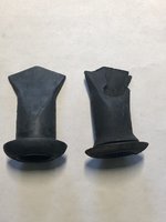
i'm looking to order the insulators to see if it solves my misfire issue.fcpeuro has them listed as distributor dust shield ? are those the ones I need ?part #1191580188 $52.49 each.thanks.
1590785979617.png
 
Picking up where I left off some time back, today I spent an hour or so out in the shop, and re-installed the crankshaft hub and the water pump.

Here's an overview of the tasks:

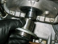
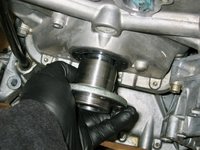
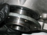
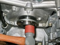
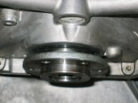
After taking a very fine piece of emery paper to the slight gouges in the top end of the crankshaft snout, to smooth them off, I began the press-on installation of the hub onto the crank. The photos below show me fitting it into position by hand. I did not have to heat it up to the recommended 50C -- it was a tight slip fit, but I was able to work it onto the crank with slight "back and forth" motions.
IMG_9546.jpeg IMG_9547.jpeg IMG_9548.jpeg


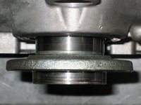
And, here the hub is (mostly) in position. A few very slight taps in a circular pattern with a plastic hammer seated things all the way down. The hub is now in position for installation of the crank bolt, and tightening to its 400Nm torque.
IMG_9549.jpeg IMG_9550.jpeg

All in position...
IMG_9551.jpeg IMG_9552.jpeg


After the hub was installed, it was time to install the water pump. This was needed so that the pointer was in position for the rotation of the engine, which will need to be done for a couple of jobs after the large crank bolt is installed and torqued. Specifically, I will need to turn the crank to 45 degrees BTDC so that I can pin the camshafts, for removal of the intake cam adjusters for the replacement of the timing chain rails. But, first things first.

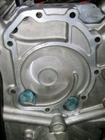
I did a final clean-off of the water pump gasket sealing surface, with some brake cleaner and a Scotch Brite pad. Then I wiped things down to remove any green Scotch Brite residue.
IMG_9554.jpeg

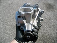
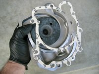
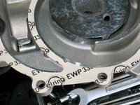
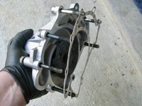
Next, it was time to begin preparing the new Graf water pump. I removed it from its box, and also the factory water pump gasket (the Graf pump also included a water pump gasket in the box, but I didn't use it). The factory water pump gasket was made by Elring, as shown in the third and fourth photos below.
IMG_9555.jpeg IMG_9556.jpeg IMG_9557.jpeg IMG_9558.jpeg


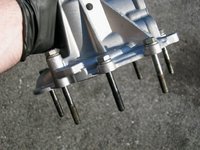
Next, I laid out the water pump bolts. There are FIVE sizes of bolts used on the water pump's eight bolts. Six of the bolts are used to install the pump initially; two additional bolts are installed when the fan clutch pulley holder, and the driver's side spark plug wire tray, are installed. I test-fit the bolts, as shown in the photo below.
IMG_9559.jpeg


With the bolts confirmed to be in the correct holes/locations, I then installed the gasket onto the bolts and slid it into position.
IMG_9560.jpeg IMG_9561.jpeg


Next, I remove the two plastic towels I had inserted into the holes in the front of the engine front cover, to keep dust out. These plastic towels are lint-free. You can see the were soaked with residual coolant from plugging these holes for the weeks since I'd removed the engine's original water pump.
IMG_9562.jpeg IMG_9563.jpeg


Then I lowered the water pump into position, and began engaging the 13mm bolts into their positions.
IMG_9564.jpeg IMG_9565.jpeg IMG_9566.jpeg


The next step was to torque the water pump bolts to the correct 21 Nm of torque. This is actually fairly tight. Per the FSM notation, it is important to ensure that the curve at the bottom right corner of the water pump housing does not interfere with the front engine cover casting. The FSM notes that the water pump housing should be ground away about 1mm if there is interference so that the water pump housing does not fully seat against the front cover.

I checked this by putting the gasket into place (before installing the pump), and then checking the gasket against the face of the pump. I also checked the fit of the pump after I'd loosely installed it, before torquing the water pump bolts. It's difficult to see, but I was able to ascertain that there was no interference, and that the water pump was able to adequately seat against the front timing cover properly.
IMG_9567.jpeg IMG_9568.jpeg IMG_9569.jpeg


Here are two views of the water pump bolts that were NOT installed. The first photo shows the right-hand bolt at the top of the pump. This is the hole that the bolt for the spark plug wire channel goes through. This will be one of the last steps in the re-assembly of the car. The second (blurry) photo shows the lower left pump bolt, which receives its bolt when the fan clutch pulley holder is installed in the near future. That fan clutch pulley holder bolt passes through this hole, which is near the engine oil dipstick.
IMG_9570.jpeg IMG_9571.jpeg


Now that the pump is installed and torqued, you can see the engine timing indicator that I painted orange/red with Laura's fingernail polish.
IMG_9572.jpeg
 
Made a quick parts order on Monday, and my parts arrived today (Wednesday) at MB Annapolis. Just a few various and sundry items, as mentioned: plastic nuts, new screws for the engine compartment side cladding, inner fender-well attachment screws, and 5 meters of new rubber sealing for the inner fender well panel edges. "While you're in there...."

149488CF-4E5F-44DB-95BA-626E6EA4969C.jpeg
 
Today, I spent about 3 hours out in the shop doing a bunch of tasks. First of all, I wanted to be able to rotate the engine so that:

a) I could drain the transmission fluid from the torque converter (and also the transmission pan) for an oil and filter change; and

b) so I could rotate the engine to 45 degrees above TDC, so I could pin the camshafts to remove the intake cam adjusters

So, to do this, I had to remove the flywheel lock. I was able to pry it out with a long screwdriver. I then replaced the harmonic balancer onto the end of the crankshaft, in the position it was in when I removed it (I had marked the position). The balancer and the crankshaft pulley (which I didn't install today) can only go onto the crankshaft in one orientation, because the six bolt holes are slightly offset, so that the hole pattern only allows the pulley and balancer to bolt onto the crank in one way. Again, installing all six crank pulley bolts into a hand-tight position confirmed that I had the correct orientation. This will be helpful for eventual re-assembly.

I then inserted the 27mm crank bolt, so that I could use a socket to turn the engine. I DID NOT torque down the crank bolt to its 400 Nm, mainly because I still have the car up on jack stands because I'm working underneath it. But I was able to use the crank bolt to turn the engine by hand.

As you know, I had previously (and it turns out, prematurely) removed the timing chain tensioner. And, I did not re-install it before I gave the engine 1-2 turns by hand to find and confirm the 45 degree Before TDC mark. I realized my mistake after turning the engine, and then I re-installed it into position, but didn't torque the tensioner down (as I will be removing it again shortly).

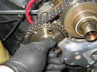
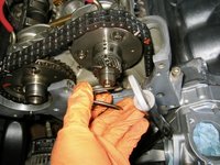
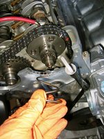
I was able to "pin" three of the four cams into position with the crank at the 45-degree mark, but the fourth (passenger side exhaust cam) cam evidently jumped a tooth, and it is about 1 cm (probably one tooth) off position. So, I will have to remove the exhaust cam sprocket (which I was going to do anyway) and re-orient it correctly, and pin it. Some quick consultation with GSXR suggested this.

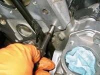
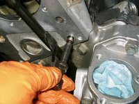
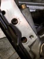
Here are a few photos that show the crankshaft at 45 degrees Before TDC, as well as one of the two pins inserted in the passenger-side cam, and the distance between the end of the pin and the hole. This pretty clearly shows that we think is a skipped exhaust cam tooth.

unnamed3.jpg unnamed2.jpg unnamed1.jpg

So, very minor setback and a few extra steps, but nothing too horrible. From what I can see, the three pinned cams are pretty much RIGHT ON the 45-degree mark, indicating that my timing chain (at 142k miles) has minimal to no stretch, and also that my upper timing chain rails are in good condition (which I was generally able to confirm visually, as well).

In the meantime, since I was able to rotate the engine, I moved it so that the drain plug for the torque converter was exposed. I then loosened the plug, and drained the converter. The plug is nearly stripped, but I have a couple of extra plugs (and washers) in my parts stock, so I'll replace it. I then moved on to the transmission pan, and drained that as well. I then replaced the plugs.

The transmission fluid had exactly 25,000 miles on it, and I had last replaced it in February, 2013. It came out with a slight orange-ish tint, but generally was still of good color, and smelled OK.

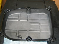
The next step will be to remove the transmission pan and gasket, empty it and check for any debris in the bottom of the pan, install the factory magnet in the bottom of the pan, change the filter with the proper "129" part number filter, and then re-install the pan with a new gasket.

Lastly, I decided (while doing some cleaning on the underside of the engine, while the transmission pan drained, to replace the two transmission cooling hoses on either side of the engine compartment, next to the radiator. It was simple to do this while the radiator was out of the car, and I had both hoses in my parts stock.

I'll have to look in my records, but it appears that perhaps when I lived in Portland, I had my mechanic shop replace at least one of the hoses with a new MB hose, because the hose I removed had a 220 part number on it. However, the 220 hose was a bit spongy (although not seeping/weeping/leaking), so I decided to just replace both of them. The other hose, on the passenger side, which attaches to the bottom of the radiator, was a CRP (Continental Rubber Products) hose. The replacement for it in my parts stock was an identical hose.

At this point, I wrapped up for the evening, and called it a day. I'll finish the transmission drain tomorrow, and will refill the transmission later on near the end of the project.

I took a few photos, not that many today, but will add the photos to a later post.
 
Just a tip Gerry ref the skipped chain.

Yes that will always happen on that sprocket if you turn the engine without the tensioner fully installed. (Dont ask how I know)

My tip here is to make sure and pin the other 3 cams now and keep them pinned. Then before you try to remove the sprocket and / or move the chain over one link you must do 2 things to save you pulling your hair out:

1: Make temporary reference marks where the sprocket is at now so you know where to move it and also where It was if it skips during re-setting. (The timing hole isn't always readily visible)

2: Make sure and counter hold the camshaft at all times with a wrench or similar on the hex halfway down. This is because the moment you undo the chain and put any form of movement on the cam, it will then skip around on its own to where the lobs have least pressure putting things way off and creating more faffing.

Just keep hold of it and carefully turn until that 4th pin goes home and you will be good.
 
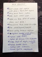
This is the original list of stuff that I drew up on a piece of note paper, about 18 months ago, to originally scope out this job.

You can see from my check marks that I’m mostly done, with the major outstanding item being the upper timing chain rails. The water pump has been replaced, but I haven’t installed the new thermostat, so I can’t mark that off as complete yet.

Everything else will get replaced as part of the re-assembly.

Funny how a “memo pad” task list can turn into a monstrous job.

71DD44BD-AAFF-4C47-BEC7-5661282B44A8.jpeg
 
Wait until you have to install the short elbow hose on the thermostat outlet. That is a total pig to do in frame. First one I did I figured it would take me maybe 5-10 minutes. Wrong. If there are shortcuts or hacks on how to do this, I'm all ears.

Dan
 
Wait until you have to install the short elbow hose on the thermostat outlet. That is a total pig to do in frame. First one I did I figured it would take me maybe 5-10 minutes. Wrong. If there are shortcuts or hacks on how to do this, I'm all ears.

Dan
Ive done that per my thermostat HOW-TO a couple years back. Piece of cake.

Will be even easier with things disassembled this time. I’ll fit it on the therm housing and then install the second piece.
 
Ive done that per my thermostat HOW-TO a couple years back. Piece of cake.

Will be even easier with things disassembled this time. I’ll fit it on the therm housing and then install the second piece.

Haven't done it in some time, so I'll have to take a look at your DIY. Hope there is a good shortcut for installing that hose. It can be unpleasant...

Thanks!

Dan
 
Haven't done it in some time, so I'll have to take a look at your DIY. Hope there is a good shortcut for installing that hose. It can be unpleasant...

Thanks!

Dan

 
Yes I can understand how the parts list grows :)

I had just recently done a full m119 engine refresh and transmission re-seal. Full timing setup and head gaskets, valve job etc. Don't know what that cost in parts alone but it was thousands, so many orders over months.....

But the way I see it that engine is good for another 30 years of service so money well spent.
 
I'm into my car for just over $5k in parts so far. I didn't think it could be possible with just regular upkeep and maintenance/incidental repair items. When I got it all it seemed to need was a front crank seal and the reverse clutches. You would never have thought it was this bad from taking a cursory look at it. It ran right and didn't give any reason to think it needed anything mechanically.

I don't know about 30 years but if I can get ten more without a leak anywhere I'll be happy because that's what I'm shooting for.
 
Its German, which translates in English to: fluid leaks.
PS hoses, trans cooler lines, SLS feed lines, heater/radiator hoses are going to leak sooner or later.

Replace as you go....
 
I'm into my car for just over $5k in parts so far. I didn't think it could be possible with just regular upkeep and maintenance/incidental repair items. When I got it all it seemed to need was a front crank seal and the reverse clutches. You would never have thought it was this bad from taking a cursory look at it. It ran right and didn't give any reason to think it needed anything mechanically.

I don't know about 30 years but if I can get ten more without a leak anywhere I'll be happy because that's what I'm shooting for.
You are correct. My car ran perfectly before I tore the top end down starting in early April, save for a check-engine lamp that had to do with the smog pump and EGR system (which ended up being vacuum disconnections that I found). I have no quesiton that my car would have continued to run quite well for some time into the future, perhaps save for the lower wiring harness and the ETA, both of which were original and needed rebuilding/replacing (though both of which had no obvious issues with how the car ran).

Now you see why I created all of these "rules" about deferred maintenance being $5k+ for cars with under 100K miles, and $10K+ for cars with over 100K miles. It's damned true, as you are finding out. This is with dealer or competent independent repair shop labor, of course, not DIY labor. But even as you and I are finding, the parts costs (discounted significantly) and DIY labor DO add up and are not insiginficant.

Plenty of folks have given me a hard time about my deferred maintenance Laws over the years, but they have borne out to be true again, and again, and again. Even folks who didn't believe it, have become believers after they had to pay the bills.
 
Just a tip Gerry ref the skipped chain.

Yes that will always happen on that sprocket if you turn the engine without the tensioner fully installed. (Dont ask how I know)

My tip here is to make sure and pin the other 3 cams now and keep them pinned. Then before you try to remove the sprocket and / or move the chain over one link you must do 2 things to save you pulling your hair out:

1: Make temporary reference marks where the sprocket is at now so you know where to move it and also where It was if it skips during re-setting. (The timing hole isn't always readily visible)

2: Make sure and counter hold the camshaft at all times with a wrench or similar on the hex halfway down. This is because the moment you undo the chain and put any form of movement on the cam, it will then skip around on its own to where the lobs have least pressure putting things way off and creating more faffing.

Just keep hold of it and carefully turn until that 4th pin goes home and you will be good.
Thank you for this comment. I am dealing with a similar issue. Left side exhaust cam seems to have jumped one tooth. My plan is to follow the directions above. Pin the other three cams then release the tensioner in order to lift the chain and roll left exhaust cam forward one tooth and pin. I plan to hold the left exhaust cam in place with a needle nose vise grip as I don't have the special wrench. My question is how much force should I expect to need in order to hold the cam in place once the tensioner is released and I left the chain?
 
:update:

A collection of a few updates of recent days.

After installing the water pump onto the front of the engine, I temporarily installed the balancer onto the nose of the crankshaft. This was so I could get a reference on crank position for pinning the camshafts.

The first photo below shows the temporarily installed balancer. The second photo shows the crank angle marker moving along the balancer. Note the line I had made earlier in black marker that showed the initial orientation of things when I removed the crank balancer and pulley to replace the front crank seal. The third and fourth photos show the cams pinned at the requisite 45 degrees before top dead center. The fifth photo shows the 45 degree BTDC mark indicated on the crank balancer scale.
IMG_9573.jpeg IMG_9574.jpeg IMG_9575.jpeg IMG_9576.jpeg IMG_9577.jpeg


This shows the discrepancy between the pin and the pin-hole caused by the chain skipping a tooth. This sprocket will need to be rotated one tooth so that the chain lines up and the pin properly inserts into the holes.
IMG_9583.jpeg


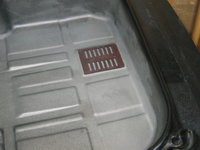
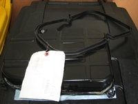
With preparations for the chain sprocket adjustment in order, I turned my attention toward draining the transmission fluid from the torque converter and the drain pan. I followed the normal protocols and procedures for doing this. I didn't find any chunks or other matter in the bottom of the transmission pan, which I was happy to see.

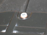
I was not happy with the condition of the plug on the drain pan, as it was close to being stripped. I pulled a new plug and washer from my parts stash, and replace them straightaway as I prepared the pan for re-installation.
IMG_9587.jpeg IMG_9588.jpeg IMG_9589.jpeg IMG_9590.jpeg


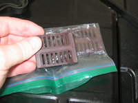
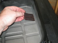
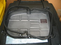
Next, I installed (for the first time) a factory magnet into the bottom of the inside of the transmission pan. I had wanted to do this for years, but it had been 2013 the last time I had the transmission pan opened up.
IMG_9586.jpeg IMG_9592.jpeg IMG_9593.jpeg IMG_9594.jpeg


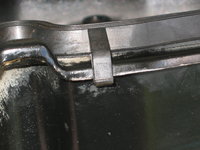
Then it was time to install a new rubber seal to the lip of the pan, and ensure it was evenly installed all along the circumference of the pan.
IMG_9591.jpeg IMG_9595.jpeg IMG_9596.jpeg IMG_9597.jpeg IMG_9598.jpeg


Then, cinch down the newly installed drain plug and copper washer.
IMG_9599.jpeg


Next up, it was time to remove and replace the rubber grommets that comprise the lower radiator mount. These merely press into the lower radiator support on the E500E. Simple act to reach down, remove, and press in new grommets. The old ones were OK, but at $3.50 apiece, why not replace these original underhood rubber items? You can see the new items, and then in the last photo the old (left) and new (left) grommets.
IMG_9606.jpeg IMG_9607.jpeg IMG_9608.jpeg IMG_9609.jpeg


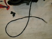
From there, I decided to migrate to the removal of the smog pump from the car, so that I could replace its cracked insulation on the power cable. Note that the pump had been removed from the engine, and was just sitting on the bottom of the radiator support while tethered by its long cable. The cable disappeared somewhere under the passenger side headlight. Some consultation with the @gsxr indicated that the smog pump cable terminated in a normal two-prong connector in the fender/headlight area, so I resolved to remove the headlight, turn signal, and the inner plastic air scoop bucket so that I could access the smog pump connector, and remove it from the car.

I don't go into the details of removing the headlight here, as it is documented elsewhere, but it is generally a fairly straightforward process. I did snap a few photos here, mostly of random steps in the process.
IMG_9610.jpeg IMG_9611.jpeg IMG_9612.jpeg IMG_9613.jpeg IMG_9614.jpeg


Here, in the next few photos, you can see some of the damage I found (and had previously observed) from rodents chewing into the sheathing of the various lines in the area. All of this is being replaced.
IMG_9615.jpeg IMG_9616.jpeg


This is what things look like with the headlight removed, but with the air scoop bucket still in place. You can see plenty of degraded foam sealing and cushioning, which will be replaced.
IMG_9617.jpeg


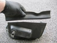
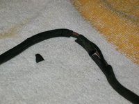
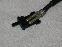
Here is a view of the smog pump cable insulation, in its crumbling state. This is after I removed and unplugged the smog pump from its connector. I'd venture to say that all of yours' is probably not too different from this !!
IMG_9618.jpeg IMG_9619.jpeg


A few views of the headlight air scoop / bucket after removal from the car. You can see the drain hoses attached to it. One drain hose is from the headlight; the other is in the bottom of the air scoop and drains accumulated water downward. In the fourth photo below, you can see in the large rubber water drain, SIGNIFICANT rodent damage to it. A rodent was VERY determined to get at something trapped inside of that drain. Of course, new drain hoses have been ordered, and are still available from MB. In the last photo, I am removing the rubber edge seal from the bottom edge of the air scoop; this edge seal goes under the upper surface of the bumper cover.
IMG_9620.jpeg IMG_9621.jpeg IMG_9622.jpeg IMG_9623.jpeg IMG_9624.jpeg


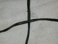
The next step was to bring the smog pump into the (cool) house, and place it on my kitchen table. You can see the exceedingly poor condition of the insulation, close-up.
IMG_9625.jpeg IMG_9626.jpeg IMG_9627.jpeg


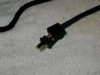
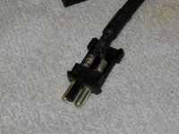
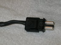
Removing the connector from the two wires that connect to the smog pump. Easy to pry apart with the fingertips.
IMG_9628.jpeg IMG_9629.jpeg IMG_9630.jpeg


Interestingly, the outside of the connector was marked "Made in W. Germany" -- :lolol:
IMG_9631.jpeg


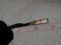
Measuring the length of the smog pump cable, it came in at about 28 inches. This was important for the length of the shrink-wrap tubing that I would be preparing to recover the wiring with. I was generally able to peel the cracked insulation off of the cable with my fingers, and in a couple of places the point of a utility knife.
IMG_9632.jpeg


I slid a new length of shrink-wrap tubing onto the smog pump cable, and heated/shrunk it. Worked a charm. Here's what it looked like.
IMG_9633.jpeg IMG_9634.jpeg


After I shrunk a short length of heat-shrink tubing to the connector end of the cable, I then re-installed the prongs back into their plastic housing in the correct order.
IMG_9635.jpeg IMG_9636.jpeg


The last task for the day, before I had to break off to go to the doctor's office, was to remove the top chain guide in preparation for the loosening of the timing chain and moving of the sprocket to the correct orientation.
IMG_9600.jpeg IMG_9601.jpeg IMG_9602.jpeg IMG_9603.jpeg IMG_9604.jpeg IMG_9605.jpeg
 
Ref the transmission magnets for sure they are a great idea and dont come in the pans from factory.

I did note a cunningly placed magnet recently in a 722.6 I cracked open. The previous installer and placed this magnet on the filter metal body itself just beside the intake point. That is a great idea actually since a portion of the filter that sees most of the return fluid flow becomes magnetized :approved:
 
This afternoon I spent about an hour out in the shop, and did a couple of things.

First, I cleaned up the plastic headlight bucket/air scoop for the passenger side. It was dusty and dirty in a few places, but cleaned up quite nicely. I have the rubber drain (which had partially been eaten by rodents) on order from MB in Germany, and it should be here tomorrow or Friday. I ordered a second one for the other headlight bucket/air scoop for the driver's side.

Second, I was able to rotate the exhaust cam and get the exhaust cam sprocket properly lined up and pinned. So that now, all four cams are properly pinned.

To do this, first I removed the timing chain tensioner (again). I had, in my last installment, removed the top timing chain plastic guide. You can see a close-up of the timing chain tensioner in the first photo below. It is held to the bottom of the cylinder head by one 13mm bolt, and one 13mm nut. It was MUCH easier to access them by removing the headlight, as this gave a better angle.
IMG_9638.jpeg


Removing the timing chain tensioner from the car.
IMG_9639.jpeg


Next, with the chain loosened, I made a rookie mistake (again!) and played around with the chain, pulling it off of the exhaust cam sprocket a bit. Of course, with the cam being unpinned and under tension it rotated and got out of alignment by another two or three teeth!! You can see in the fist and second photos below, the further mis-alignment caused by this, with the pink fingernail polish on the chain and sprocket. You can also see the black arrow I scribed on the sprocket, to indicate the direction that the sprocket would need to rotate (originally two teeth, now FOUR teeth with the further slippage!) to come back to proper alignment.

So, I removed the three exhaust cam sprocket bolts which are T-30 Torx bolts. They came off relatively easily, as shown in the two photos below.
IMG_9640.jpeg IMG_9641.jpeg


After loosening the sprocket, I was able to move it away from the end of the camshaft slightly. Then, as in the second photo below, I used my special MB cam wrench (which has a thin profile, to grab onto the flat areas of the cam) to rotate the cam backward. This allowed me to pin the cam properly with the fourth pin (shown in the third photo below).
IMG_9642.jpeg IMG_9643.jpeg IMG_9644.jpeg


After this, I was able to rotate the sprocket inside of the chain to get it aligned properly so that everything is in sync, and the positioning dowel on the end of the cam lined up with the hole in the sprocket. Also, all three of the mounting bolt holes in the sprocket lined up properly with the threaded holes in the exhaust cam.
IMG_9645.jpeg

All of this was a BIG relief, and I am happy that I was able to get the cam pinned and sprocket and chain in the proper positions. I'll mark these with another color of fingernail polish for final assembly.

I will leave the exhaust cam sprocket off of the cam for now, and the next step is to remove the intake cam adjuster and sprocket (while the intake cam and exhast cam remain pinned). This will relieve all tension on the chain, and allow me enough slack in the chain so that I can remove and replace that side's upper chain rail. Then I'll have to do the same thing on the driver's side (except that there are TWO rails on that side to remove and replace).
 
While I was coming home from the Doctor's office this morning, an email came in from MB of Annapolis that my parts order of Monday morning was ready for pickup. Both of the parts had to come from Germany.

The first part was the drain for the headlight bucket/air scoop, to replace the one that had been chewed open by rodents. You can see a side-by-side comparison of the new rubber drain with the rodent-eaten one. I got a second one for the driver's side headlight bucket/air scoop, which I won't rest at night until I remove, clean, and service.

92D5BD3E-D8B9-4796-90D5-7279CDC140C0.jpeg 19670848-6DFC-44C6-B013-3628B3405BF5.jpeg

The second part of the order was the foam piece that seals the headlight air bucket. This is a simple adhesive foam piece that attaches to the headlight bucket/air scoop, and seals it against the frame of the car. I got two of these as well -- one for each side.

75D266CE-9E01-4C0C-A2D6-61926996DFE7.jpeg AB8D9A36-C493-4D1B-BCE8-858DC11036C8.jpeg 63F44FB6-9B24-4ECE-875A-0A335C74636A.jpeg

Note that one of the foam pieces was made in 2004 (marked DaimlerChrysler), and the other one was made in 2018.

These two "soft" parts will complete the refurbishment of the headlight air scoop on the passenger side of the car.
 
Refurbishing the passenger-side air scoop / headlight bucket after cleaning and receiving parts.

A couple of views of the cleaned scoop, ready to receive a new rubber drain.
IMG_9646.jpeg IMG_9647.jpeg


Inserting the new drain into the hole in the scoop.
IMG_9648.jpeg IMG_9649.jpeg IMG_9650.jpeg


Installing new foam sealing around the inside base of the scoop, where it meets the headlight frame of the car.
IMG_9651.jpeg IMG_9652.jpeg IMG_9653.jpeg


The finished installation of the foam, along with the short section of left-over foam. Home Depot insulation foam could probably be used for this job. The MB foam (discounted) is around $10.50 per air scoop, so it's not cheap for what it is.
IMG_9654.jpeg
 
Not too much progress over the weekend, due to having to go to a funeral/wake, and the having guests over all afternoon on Sunday. So no time to get stuff done :(

This morning I made another MB parts order, for new fog-light lenses and a new factory grill insert to replace the "600 style" aftermarket insert that I've had for many years. That insert is starting to get faded and weather-worn, and I never minded the "factory" grill insert anyway. I believe I have spare aluminum trim strips that I can use to refresh the trim.

I replaced the fog lamp lenses many years ago (never used Lamin-X on them). When I replace them, I will definitely add some of my own Lamin-X to them. One of my fog lamps has a small rock chip in it. Still, I can't complain about the service they've given me for the past 17 years. The fog lamp lenses aren't cheap.....

I also added new front strut rubber boots and bump stop rubber onto my order, for the eventual replacement of the front struts with new MB factory units with the internal rebound-limiting springs. That will be in the future, though.

Fortunately all of these parts are located in the US, so I'll likely have them in hand by Wednesday or Thursday this week.
 
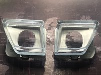
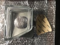
Fresh set of fog light lenses, ready for a fresh set of Lamin-X.....

One lens was made on May 20, 2020. The other was made Sept. 23, 2019.

Fresh production, indeed.

0CDFC99A-F10C-4B31-B548-C4BDC58E7818.jpeg


And with Lamin-X installed.

EF919C9B-2609-41A9-ACB8-7512CEF631B8.jpeg
 
Put about 90 minutes into things this evening out in the shop, and started making headway toward the final push to get things done.

Main goal for tonight was to get the passenger side timing chain rail removed and replaced with a new rail. To do this, I had to remove the right-hand (passenger) intake cam sprocket and adjuster, so that I could loosen the timing chain enough to remove the timing chain rail.

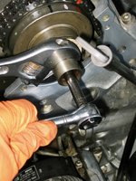
The first step to removing the intake cam adjuster is to remove the screw that holds the armature to the end of the cam adjuster. This is (on first glance) difficult, because the two parallel flat spots on the armature look like they require a very thin wrench to "hold" the armature from rotating while the 8mm center screw is loosened.
IMG_9655.jpeg


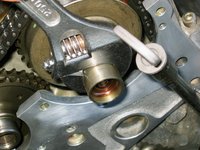
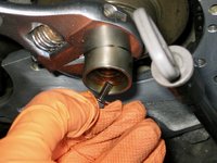
However, there is a little "trick" -- you can pull the armature straight outward a few millimeters, and this provides enough room so that you can get a conventional wrench (I used a Crescent wrench) to get a "bite" on it, so that the center screw can be loosened. You can see this in the photos below.
IMG_9656.jpeg IMG_9657.jpeg IMG_9658.jpeg


Remove the center screw, and then pull the armature straight off of the cam adjuster.
IMG_9659.jpeg IMG_9660.jpeg


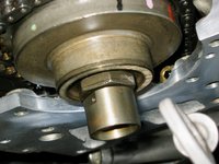
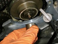
After the armature comes off, you will see a large nut. I used my handy M104 cam holding tool to loosen, and then remove this large nut, as seen below.
IMG_9661.jpeg IMG_9662.jpeg IMG_9663.jpeg IMG_9664.jpeg


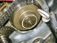
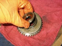
After the large nut is removed, you can then remove the cam adjuster mechanism basically as a unit. There is a center cap behind the large nut, and the sprocket assembly is in two pieces, but mine came off as a single unit. As you remove the mechanism, carefully lift the timing chain off of the sprocket. There should be enough slack in the chain to do this, because you have already loosened and removed the exhaust cam sprocket from the end of the exhaust cam.
IMG_9665.jpeg IMG_9666.jpeg


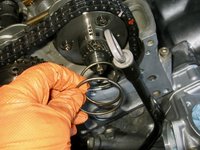
After removing the adjuster mechanism and setting it aside, you will see a large, conical spring. Pull the spring straight off. Note that the smaller end of the conical spring goes TOWARD the camshaft -- an important note for re-assembly.
IMG_9667.jpeg IMG_9668.jpeg


Removing the front cap from the cam adjuster mechanism.
IMG_9669.jpeg


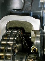
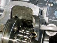
Here are a couple of views of the top end of the upper chain rail, as pinned to the inside of the cylinder head.
IMG_9670.jpeg IMG_9671.jpeg


The two dark circles indicate the two threaded pins that hold the upper chain rail in place.
IMG_9672.jpeg


Here I employ my chain rail pin puller (which I obtained for my M117 and M104 top-end rebuilds), and screwed it into the first pin. Use a pair of 14mm wrenches to counter-hold and screw the pin puller in to remove the pin, as shown in the next few photos.
IMG_9673.jpeg IMG_9674.jpeg IMG_9675.jpeg IMG_9676.jpeg


Here, the pin is almost removed, and then pulls straight out of the cylinder head.
IMG_9677.jpeg IMG_9678.jpeg


After removing the second pin in the same manner, you can grab the timing chain rail, and lift it carefully out of the cylinder head past the timing chain.
IMG_9679.jpeg


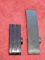
As I lifted my chain rail out of the head, I let out an audible gasp ... my timing chain rail was BROKEN, with the bottom 1.5 inches (below the lower pin) totally GONE.
IMG_9680.jpeg


A careful search (several times) with a bright LED flashlight down into the timing chain passage of the cylinder head did not show any evidence of the bottom part of the timing chain rail. This means that it probably was pulverized and dropped down into the engine oil-pan.
IMG_9681.jpeg


Here are a few views of the broken timing chain rail.
IMG_9682.jpeg IMG_9683.jpeg IMG_9684.jpeg


And some views of the old, broken rail next to a brand new, MB replacement rail.
IMG_9685.jpeg IMG_9686.jpeg IMG_9687.jpeg


Next up, it was time to install the new rail. The pins insert into the cylinder head in much the same way as they were removed, although it takes a slight bit of effort to line up the pins with the holes in the new rail. Once the pins were in all the way, I used a hammer to gently tap them into position, all the way in. Note that the pins are long enough so that they go THROUGH the timing chain rail, and into a hole in the OTHER side of the cylinder head. It's important to get the pins inserted all the way into the head.
IMG_9688.jpeg IMG_9689.jpeg IMG_9690.jpeg IMG_9691.jpeg IMG_9692.jpeg IMG_9693.jpeg IMG_9694.jpeg


A view of the two pins fully inserted into the cylinder head and through the mounting holes on the timing chain rail.
IMG_9695.jpeg


Next up, after the rail replacement was done, was to begin installing the intake cam adjuster mechanism back onto the camshaft.

First, install the stiff conical cam adjuster spring.
IMG_9696.jpeg


Here I separated the two parts to the cam adjuster. The smaller part that is in my hand is installed first, and pushed up against the spring onto the end of the cam. Note that there is a larger flat inner tooth that the adjuster fits into. There's also a larger flat outer tooth that the second cam adjuster piece fits into, but this is a slightly later step. The second through fourth photos below show close-ups of the cam adjuster gear teeth, and you can see the "inner" and "outer" larger flat teeth. These are there so that the cam adjuster can only fit one way onto the cam.
IMG_9697.jpeg IMG_9698.jpeg IMG_9699.jpeg IMG_9700.jpeg


At this point, dinner was being served, so I knocked off for the night. In the next sequence, I will show the installation of the two pieces of the cam adjuster mechanism, using a makeshift special tool.
 
Gerry, nice write up and a great find on that guide. I had similar on my C126 on that side, the guide broke and wedged itself out of the way, with small portions making the oil pan floor.


** Side Note: How do you like the orange Venom? **
 
The orange Venom Steel gloves (8-mil) worked out great. Even more resistant to tearing/puncturing than the black ones (6-mil). I bought a box of 90 of them, so I'll be using them for a while to come. If I like them, I'll definitely get them again. The black ones have been great and a huge improvement over other glove types I'd used in the past. First impressions of the orange Venoms is very very positive.
 
Gerry, nice write up and a great find on that guide. I had similar on my C126 on that side, the guide broke and wedged itself out of the way, with small portions making the oil pan floor.


** Side Note: How do you like the orange Venom? **
Are those from home Depot? I just want to know if that's the correct one. I got cheap ones amid the covid-19(sold out of the good ones) at AutoZone they are crap!

They had orange ones at AutoZone that were pretty good and they had a grippy Palm.
 
Are those from home Depot? I just want to know if that's the correct one. I got cheap ones amid the covid-19(sold out of the good ones) at AutoZone they are crap!

They had orange ones at AutoZone that were pretty good and they had a grippy Palm.
Venom Steel orange. Get them from Amazon.
 
Not sure of the brand names this side of the pond as my suppliers vary but yes quality orange gloves with the grippers are the only way to go for DIY wrenching. Indeed they are only disposed of when they rip so a box lasts me a while. I got 2x boxes pre lockdown and actually about to run out again so need to go to local auto parts places and see if any are available now
 
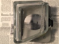
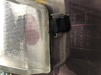
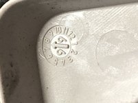
I removed the right (passenger) side fog lamp assembly from underneath the car, and pried off the lens. The date code on the lens was 6/1993, so evidently it was the original lens that came on the car.

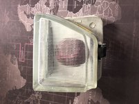
I replaced the old, sand-blasted lens with a new lens that I just received from MB, and had applied Lamin-X to. Quite a contrast, side by side !!

3F8EF720-06C0-41EC-A536-8C2D75F3EBCB.jpeg

B7C59B9D-3613-4958-A225-9C34498FD3D9.jpeg D3809CD4-8200-4A7E-B1F4-482F27AA90BC.jpeg

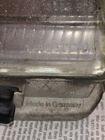
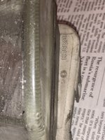
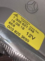
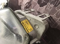
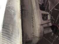
There was little to no discernable difference between the old and new lenses, physically. Same quality, and same markings on the glass. The gray plastic body of the original lens was marked "BOSCH" and "Made in Germany." The gray plastic body of the replacement lens had the same part number on it, but didn't have BOSCH or the country of origin molded into the lens itself. Instead, there was a yellow "Automotive Lighting" (AL) sticker that indicated the lens was made in the Czech Republic.

27FE8C95-1F33-40A0-8580-09D74DC7D6FA.jpeg 30E115DF-AAC4-48A3-9889-251E047E2F52.jpeg 2EC79900-52A6-40DF-9E9E-2DA3F4D553A9.jpeg E8A3D668-C565-403E-A793-B20E7E0B9CC2.jpeg E5AB9D7E-0E48-4755-8DAA-D6E9429D537E.jpeg

The new lens fit very nicely and snugly onto the body. I'll do the left-hand lens next.

:update:

I took the driver’s side fog lamp out and replaced the lens on it with the new MB lens.

That lens was dated 1999, and still had the Bosch markings on it, and “Made in Germany.” Yet it also had a yellow sticker that said Automotive Lighting and Czech Republic. The MB Star was also melted and obscured.

Here are photos of the driver's side lens:
1ADA5804-AAE8-469F-8914-EA16DD119BF2.jpeg 49350693-CA6C-41B1-8988-682D8B1B24B3.jpeg 14BB022A-3D0D-43C8-8921-442DACC4F011.jpeg BE6F863B-49A3-4FAA-87A6-EA38FC1CF8CE.jpeg 43265F4D-735A-4B19-A535-C692C1247F3C.jpeg

I remember that I replaced this lens around 2004 or 2005, because my original left-side lens was cracked by a rock. This was back when the lenses were still available on the aftermarket.

I don’t believe they’ve been available On the aftermarket for some years now. They were modestly (but not a lot) cheaper than the MB lenses.

It will be interesting to see how the Lamin-X preserves the new lenses.
 
Last edited:
I removed the right (passenger) side fog lamp assembly from underneath the car, and pried off the lens. The date code on the lens was 6/1993, so evidently it was the original lens that came on the car.

I replaced the old, sand-blasted lens with a new lens that I just received from MB, and had applied Lamin-X to. Quite a contrast, side by side !!

View attachment 106822

View attachment 106823 View attachment 106824

There was little to no discernable difference between the old and new lenses, physically. Same quality, and same markings on the glass. The gray plastic body of the original lens was marked "BOSCH" and "Made in Germany." The gray plastic body of the replacement lens had the same part number on it, but didn't have BOSCH or the country of origin molded into the lens itself. Instead, there was a yellow "Automotive Lighting" (AL) sticker that indicated the lens was made in the Czech Republic.

View attachment 106825 View attachment 106826 View attachment 106827 View attachment 106828 View attachment 106829

The new lens fit very nicely and snugly onto the body. I'll do the left-hand lens next.

:update:

I took the driver’s side fog lamp out and replaced the lens on it with the new MB lens.

That lens was dated 1999, and still had the Bosch markings on it, and “Made in Germany.” Yet it also had a yellow sticker that said Automotive Lighting and Czech Republic. The MB Star was also melted and obscured.

I remember that I replaced this lens around 2004 or 2005, because my original left-side lens was cracked by a rock. This was back when the lenses were still available on the aftermarket.

I don’t believe they’ve been available On the aftermarket for some years now. They were modestly (but not a lot) cheaper than the MB lenses.

It will be interesting to see how the Lamin-X preserves the new lenses.
Well the new lenses are used... Maybe you could polish the old lenses smooth again and use them for backups?
 
Well the new lenses are used... Maybe you could polish the old lenses smooth again and use them for backups?
That is what I'm intending to do -- keep the old lenses (which are functional) and somehow polish them (or get them polished) so that they are serviceable again. It's pretty amazing how sandblasted they are. Neither lens has any cracks or dings in it.

By the way, this is what I paid for each lens, from MB of Annapolis. The prices are a full 40% off of list price -- an EXCELLENT deal.

Left side -- $76.80 -- Lens - 1990-1995 Mercedes-Benz (003-826-35-90) | Get Mercedes Parts
Right side -- $69.60 -- Lens - 1990-1995 Mercedes-Benz (003-826-36-90) | Get Mercedes Parts


For contrast, the cost of the full lighting units:

Left side -- $198 -- Fog Lamp Assembly - 1990-1995 Mercedes-Benz (129-820-01-56) | Get Mercedes Parts
Right side -- $198 -- Fog Lamp Assembly - 1990-1995 Mercedes-Benz (129-820-02-56) | Get Mercedes Parts
Those prices are only 28% off of list. So, the lenses are a much better deal.
 
Last edited:
I spent some time (as in about four hours) over the long weekend attempting to use the "home-made" socket + bolt tool to hold the cam adjuster in place. Tried various configurations, ways of assembling and installing, and ended up not being successful. It takes a LOT of strength to hold things against that very tough spring.

In the end, to avoid further damage to my palm and hand from holding things, I just decided to spend the $100 and get the factory tool. I ordered it this morning. It is available from MB, but only in Germany, so it's not likely that I'll have it until the end of the week so that I can continue with the intake cam adjuster mechanism re-assembly (and work on the other side).

One bonus is that this same tool is applicable for the M104 engines (albeit only a single intake cam).

In the meantime, I will commence on removing the power steering pump and bracket this week, so that I can free up the pins for the lower rail in the left-side cylinder head.
 
Big load of goodies came in from MB Annapolis today. The parts ordered from Germany were ordered Monday, received today.

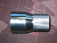
First, the $100+ tool to hold the intake cam adjuster mechanism for assembly. This tool works with not only the M119, but also the M104 and M120.
IMG_9705.jpeg IMG_9706.jpeg IMG_9707.jpeg


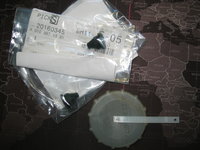
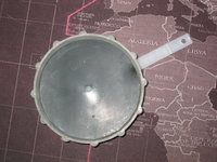
Next, a new cap and retainer, and two new rubber grommets for the washer reservoir. Also got a new rubber gasket for inside the cap. And an extra retaining strap, for the deep parts stash.
IMG_9708.jpeg IMG_9709.jpeg IMG_9710.jpeg IMG_9711.jpeg


A new hood release handle....
IMG_9712.jpeg


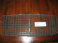
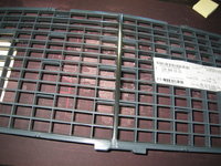
And new aluminum trim strips for the new stock W124 facelift grille insert. Yep, that's right ... after about 16 years, I'm going to go back from the "AvanteGarde" grill insert, to the stock grill look.

Note that I only received FOUR of the SIX horizontal grill trim strips that I ordered. The remaining two are on back-order, but are available. I should have these in the next week or two, hopefully. They are not cheap, I believe even the discounted price is well over $10.00 per strip (and there are six of them, plus the center grill trim strip, which is a different part number).
IMG_9713.jpeg IMG_9714.jpeg IMG_9715.jpeg IMG_9716.jpeg IMG_9717.jpeg IMG_9718.jpeg


Installing the single center (vertical) grill trim strip onto the new grill.
IMG_9719.jpeg IMG_9720.jpegIMG_9721.jpegIMG_9722.jpeg

If you are running a stock grill, you may want to hoard a set of the trim strips. The grill inserts are also still available (pre-facelift and facelift). The facelift insert was only about $35....so not that expensive.
 
This morning, I continued installing the new trim strips for the new grill insert. Since MB only sent me four of the needed six horizontal trim strips, I installed what I could. Hopefully the back-ordered items will be here in the coming couple of weeks.

NOTE: This step ONLY applies to trim strips for "facelift" (1994 and 1995 W124 models) cars. I do not know if this trim strip installation process applies to "pre-facelift" (1986-1993 model year) W124 cars. Your mileage may vary (YMMV).

One safety note: These trim strips are VERY sharp on the bottom edge. It is HIGHLY ADVISABLE that you wear a pair of gloves so as not to cut/slice your fingers on these aluminum strips. I actually sliced two of my fingers with paper-cut type slices, and this could have been avoided had I worn even a thin pair of gloves.

To install the trim strips, there are THREE different lengths involved, per factory spec. These lengths correspond to the width of the grill at each level of horizontal trim.

The top row strips must be 336mm per side.
The middle row strips must be 315mm per side.
The bottom row strips must be 304mm per side.

The trim strips, as received from MB, are of the proper 336mm width for the top row. This means that the top-most strips can just be slid into position.

The middle and bottom rows, being shorter, require cutting to bring them to proper length. I did the cutting for the middle (315mm) row, using a hack-saw blade on a piece of paper. You can see, for the middle row, how much I had to cut off of each strip -- it was about 1 cm. (Apologies for the blurry photo, but you get the gist).
IMG_9775.jpeg


It's also important that you cut the end off of the trim strip with a slight angle, as the factory did. This is so that it meets the center (vertical) trim strip properly and doesn't leave a gap.

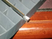
Note also that each trim strip, as received from MB, has one end that is "flattened" on the tip surface. The reason this is flatted is so that it more easily fits underneath the chrome shell that fits around the grill, and looks neater. You can see this "flattened" tip surface in the photo below. Note that this flattened end ALWAYS goes to the OUTER end of the grill, NOT the inner (center) end.
IMG_9773.jpeg


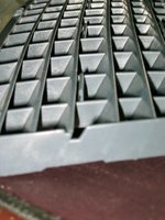
To install the trim strips, take a close look at the outer edge of the grill insert. You will see a couple of features that are important.

First, you will see a groove that corresponds with where the trim strip is inserted and slid in toward the center of the grill insert.
Second, you will see a row of small tabs that are parallel to the horizontal ribs of the grill insert.

You can see these features in the photo below.
IMG_9767.jpeg


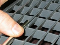
The bottom (pinched-in) portion of the trip strim is inserted IN BETWEEN this tab and the horizontal rib. You can see this in the three photos below.
IMG_9768.jpeg IMG_9769.jpeg IMG_9771.jpeg


Continue pushing the trim strip toward the center (vertical trim strip) portion of the grill insert. The photo below shows the trim strip entering the LAST of the tabs, immediately before it is pressed into place.
IMG_9772.jpeg


This photo shows both trim strips in place. As you can see, they are butted up against the center (vertical) trim strip, and there is no air gap in between the horizontal trim strips and the vertical strip. Repeat this for all six of the trim strips (as mentioned, four of them will need to be shortened per the measurements above), and you then have a finished grill insert.
IMG_9774.jpeg
 
Today, I spent about 4 hours out in the shop. The main intention was to remove the tandem pump and its backing/mounting plate, so that I can get access to the front of the cylinder head to replace both of the timing chain rails on the driver's side.

Though I made some headway, I was not successful in removing the plate from the engine, as it is held by ONE top bolt from the back-side of the engine. The other two bolts that hold it to the engine -- one on the top backside, and one under the power steering reservoir, I was able to remove.

After struggling with things for a bit, I decided to stop for the day, and attack it again at a later time when I'm fresh.

Here are a few photos of some tasks I did today.

First, I was successful in using the new tool I obtained, to re-assemble and re-install the passenger-side intake cam adjuster mechanism. I'll show this process in detail when I do the driver's side cam adjuster mechanism, but suffice it to say that the tool made the job INFINITELY easier, taking just minutes, and is WELL WORTH the $100 ... particularly if you have an M104 and an M119 (it works with both engines).

Here are a few photos of the pinned and re-assembled intake cam adjuster mechanism, with the chain marks lined up perfectly.
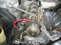
IMG_9780.jpeg IMG_9781.jpeg


It's important when you install and adjust the intake cam adjuster, that it is re-assembled in the "retard" position, which is indicated by the photo below. The photo is taken looking toward the center of the car, from the passenger side of the engine. The little block protrusion on the back-side of the cam mechanism, must be up against the edge of the slot (look under the chain), as shown. A quick check with the @gsxr confirmed that this is correct.
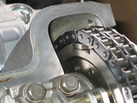
IMG_9782.jpeg


I will re-install the exhaust cam in the near future.

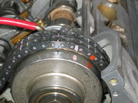
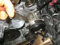
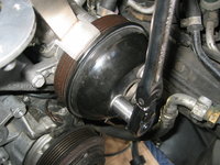
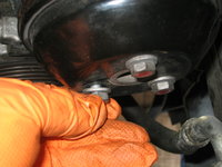
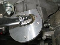
Next, it was time to do a bit more disassembly on the tandem pump. Specifically, I needed to remove the pulley. I used my trusty pulley holder, and a 13mm socket to remove the three bolts that hold the pulley to the flange on the front of the tandem pump.
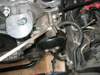
IMG_9783.jpeg IMG_9784.jpeg IMG_9785.jpeg IMG_9786.jpeg IMG_9787.jpeg IMG_9788.jpeg


Then it was time to remove the connections from the tandem pump. Note that there are three hoses that must be removed -- two connections that go to the SLS system (front of the pump), and one that goes to the power steering system (the second power steering connection goes into the power steering fluid reservoir).

I removed these connections with a Philips head screwdriver, and a 17mm open-end wrench.

First I removed the plug I'd made of a piece of lint-free towel. Then I used a 15mm Allen socket to remove the tube that screws into the reservoir plate, and goes through the infamous "short hose" from the reservoir to the tandem pump.
IMG_9789.jpeg IMG_9790.jpeg IMG_9791.jpeg IMG_9792.jpeg IMG_9793.jpeg IMG_9794.jpeg


Then I removed the tube, and its aluminum washer.
IMG_9795.jpeg IMG_9796.jpeg


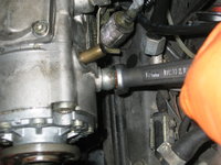
The next thing I removed were the hose connections at the tandem pump. As mentioned, the connections are despatched by a Philips head screwdriver, and a 17mm wrench. Make sure you put a drip container below, to catch the power steering fluid and SLS hydraulic fluid that will leak out of the lines when you loosen and remove them. It won't be too much fluid, but a drip/drain pan will make things much more pleasant.
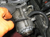
IMG_9799.jpeg IMG_9800.jpeg IMG_9802.jpeg


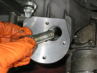
Removing these connections allows you either to remove the tandem pump itself, or the pump+backing plate as a unit.

As a next step (and I did not capture this photographically), I removed the "S" hose to the power steering pump. This is removed via two ring clamps at either end of the hose, which are loosened with a long flat-blade screwdriver. From my tandem pump job some years back, I had one clamp accessible from underneath the car, and the other clamp accessible from the engine compartment. You can also orient it so that both clamps are accessible from underneath the car -- however you want to do it. I will probably re-install the "S" hose with both clamps pointing downward, so I can loosen both from under the car.

Removing the "S" hose makes MUCH more room available for getting to the bolts that hold the tandem pump to the plate (the two from behind), as well as the top-most bolt that holds the plate to the engine from the back-side. It's probably possible to remove these bolts without removing the S-hose, but it sure made more room available -- a lot more comfort for very little work.

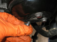
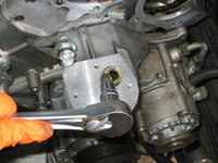
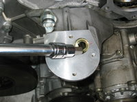
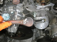
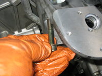
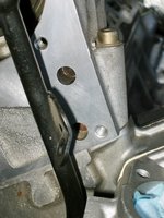
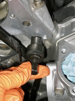
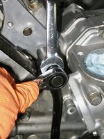
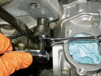
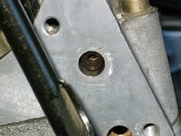
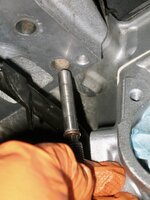
I spent the better part of an hour trying to get that top bolt for the tandem pump backing plate loosened (it's a 13mm bolt), but I was not able to easily do it. I was able to get the other two tandem pump backing plate bolts loosened -- another 13mm bolt that goes into the cylinder head edge from the back-side (which can be accessed from the engine compartment, although just barely), and a 6mm Allen bolt that is located under the power steering pump reservoir.

You can see the process for removing the 6mm Allen bolt for the tandem pump backing plate.
IMG_9806.jpeg IMG_9807.jpeg IMG_9808.jpeg

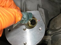
It's IMPORTANT to note that this 6mm Allen bolt for the backing plate requires the use of the orange koala-claw goo when it is re-installed, as it enters the timing chain compartment. This anaerobic goo helps seal this bolt and threads from oil seepage.

The next thing I did was to install the new armature onto the intake camshaft on the passenger side. This is the "second series" design of armature, and it is required when using replacement cam solenoids. Here are a few views of the solenoid, installed.
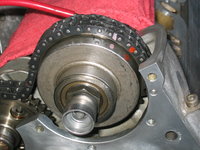
IMG_9803.jpeg IMG_9804.jpeg


Here is the "old" armature and the "new" armature, side by side. It's a bit difficult to tell from the blurriness of the photo, but the interior profile of the armatures is different -- the "old" design armature has a more rounded profile, and the "new" design armature has a square profile. This is important and notable, because the new design cam solenoids have an interior profile that fits these revised armatures. The old and new design armatures and solenoids ARE NOT compatible nor interchangeable.
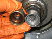
IMG_9805.jpeg


Lastly, I removed the grill from the car's hood, and then removed the "old" 140-style (Avantgarde) insert from the grill frame. The Avantegarde grill, which I installed on the E500 probably 15 or 16 years ago, was starting to show its age in the slats, being sand-blasted and weather-worn. The aluminum strips were also dull and sand-blasted. Looking at the old Avantgarde grill, I saw a W140 part number on the bottom of it, so indeed it is a cut-down W140 part that I purchased on the aftermarket.

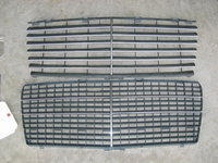
Here are the new and old grill inserts, side by side. Note that the new grill insert is still missing two of its horizontal slats, which are back-ordered from MB and should hopefully be received in the next week or two. In the meantime, I will polish and clean the chrome grill shell (which doesn't have any major damage other than some faint stone dings and sand-blasting), and re-use it.
IMG_9809.jpeg


That was about all for today. I'll attack that tandem pump backing plate with a fresh mind and pair of eyes, and will try to get to it tomorrow (Monday) so that I can continue the timing chain rail replacement on the driver's side of the engine.

Thanks for your interest !

Cheers,
Gerry
 
Looks like they are out of stock.

Back in stock .... but just barely. You have to check every single day.
Screen Shot 2020-07-13 at 7.06.00 AM.jpg


By the way, I did go through a couple of orange gloves yesterday in the course of my wrenching, but these gloves had been re-used at least two times (including at the wrecking yard), and the holes were "pinhole" type holes caused by pinching when tightening fasteners ... not catastrophic "rip" or "split" type failures that you normally find with gloves.
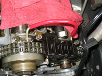
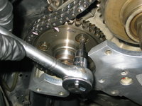
These gloves are tough cookies. The only thing I have with them is that I got the "XL" size, and my hands really take the "L" size. So they are a little large at the fingers, with a bit extra glove material at the fingers. If I can get the "L" size next time, I will do that. YMMV depending on the size of your hand/fingers.
 
I put in a small order of parts today, mainly for replacement hardware and washers for the SLS and power steering systems. The small rubber hoses from the bottom of the SLS fluid tank, and the rubber hose from the SLS portion of the tandem pump (both are part 114 997 04 82, purchased by the meter) are original, so I thought I'd replace them as they are quite old. I have a length of "short hose" from my previous replacement, but "since I'm in there" I'll replace the short hose again. The "S" hose for the power steering is in good condition, though I may replace its aluminum heat shield outer housing (I have a couple of spare meters of it) just to make things look pretty.

This is, of course, in keeping with replacing all of the rubber items I am encountering underhood. Since my SLS fluid tank is quite yellowed, and I'm removing its lower hose to replace it anyway, I think I will replace it with the NOS SLS tank that I have sitting out in the garage. Sort of a whim, but what the heck.

I did purchase all new hardware for the tandem pump and its bracket, to connect to the engine cylinder head/block. I also ordered a new set of 124 grill trim strips, because you never know if they are going to go out of stock or not.

Also, one last question -- does anyone know how to re-finish an Avantgarde-style (W140) grill insert? My reason for asking is either I'm going to sell mine (to someone who wants to refinish it) or I'll refinish it myself and keep it. I just don't know the best way/process to refinish a weather-worn insert.
 
A small note on my hose experience (short sls tandem side) was I needed one more crank of the jack to raise the engine on the DS mount replacement and when I did, that hose tore right in half at the fender side connection. Quite a mess.

I had thought those were good hoses, but they were rotted from the inside out, obscured by the outer fabric weave. Not sure why they didn't get heat shielded. I used the proper hose and replaced them on both sides from pump to cooler and to the bottle.
 
For that rear power steering bracket bolt I recall getting it with some wobble extensions from behind. That is with the ratchet halfway back on the exhaust manifold. Worked well at the time in my 500E

Or a variety of banana / curved spanners helps too. In particular for flex disc bolts and fasteners like that pesky PS bracket
 

Who has viewed this thread (Total: 2) View details

Back
Top