• Hi Guest !

    Welcome to the 500Eboard forum.

    Since its founding in late 2008, 500Eboard has become the leading resource on the Internet for all things related to the Mercedes-Benz 500E and E500. In recent years, we have also expanded to include the 400E and E420 models, which are directly related to the 500E/E500.

    We invite you to browse and take advantage of the information and resources here on the site. If you find helpful information, please register for full membership, and you'll find even more resources available. Feel free to ask questions, and make liberal use of the "Search" function to find answers.

    We hope you will become an active contributor to the community!

    Sincerely,
    500Eboard Management

SLS adjustment

.
I should like to learn the SLS-function in detail and post a description, but here is a brief explanation after fidling with it on my own. The system is described in the enclosed docs in post #51 and #52, and here is the specific FSM for the SLS:


The Self-Levelling-Suspension works very well for many years and doesn't call for much attention, so most owners doesn't wrench much on it. However, I like to point out a couple of "Nice-to-know". All functions below work along to sustain the car at a preset height. If some of them fails, wear out, start leaking etc.. the suspension height and behaviour will fail in one or another way.

Function
The rear end of the car is held up by 3 supporting functions;
  • the springs
  • the SLS-hydraulic pressure in the shocks
  • the gas chambers in the spheres
Height

  • the springs takes most of the weight, but won't hold the car alone
  • the SLS pressure supports the springs and keep the rear end at a preset level
  • the spheres makes the ride smoother, they blends out the rough road surface feeling
Problems
I've taken the SLS-valve apart to pieces, I even cut & split a bad valve to view it inside and learn the function. It has a simple function and I would say the internals hardly wear out and would last throughout the cars lifetime. The main problems with the SLS-valve is deferred oil change so they clog up with sludge, or they start leaking past the valve stem sealing or at some of the ports. They do also have a prone location under the car without protection, so over time they will corrode and may get stucked. Additionally do the linkage wear out, and the pivot arm clamped to the swaybar may come loose or get damaged. Besides these factors - it is no point to open up the valve to inspect inside, it is no hidden surprises in there for any problem solving.

Lowering
The SLS-valve has a neutral position, this is the preset position for the height. The valve operates constantly around this point and balances between supporting pressure to the suspension if the car is loaded – or bleeding off pressure if the car is elevated above preset height. When installing lowering springs, the SLS-valve is pushed into the position for adding pressure constantly and try to lift the car back to the preset position. The pressure manage to partly lift the car back up, but it stops when the springs doesn’t give more lift, simply because they are shorter. The SLS-valve is now left in constant pressure support mode, and it will not work properly as a self levelling system because it never reaches the preset neutral position. So when lowering the car, the SLS-valve should always be adjusted accordingly back to its neutral position, and allow it to work as intended. The neutral position is shown in the bottom view on image 8 below. I use a 4mm screw to keep the lever at the neutral position during assembly and fine adjustment.

Maintenance
The maintenance is described in the FSM, but it is important to use the proper SLS hydraulic oil for the system; PN 000 989 91 03. The SLS-system has tiny oil lines and small pockets and this oil is specially developed to avoid formation of sludge/deposits at any operating temperatures.

I hope this gave a brief understanding of the system function, but please arrest me if I'm wrong on something here.


:bbq:

-arnt-
 

Attachments

  • SLS bad.jpg
    SLS bad.jpg
    548.8 KB · Views: 76
  • SLS-valve positions.jpg
    SLS-valve positions.jpg
    178.8 KB · Views: 94
  • Hydr.oil 000 989 91 03.jpg
    Hydr.oil 000 989 91 03.jpg
    686.4 KB · Views: 78
  • SLS parts.jpg
    SLS parts.jpg
    550.3 KB · Views: 70
  • SLS inside.jpg
    SLS inside.jpg
    727.4 KB · Views: 61
  • SLS open.jpg
    SLS open.jpg
    719.9 KB · Views: 57
  • SLS ports.jpg
    SLS ports.jpg
    608.2 KB · Views: 55
  • SLS back.jpg
    SLS back.jpg
    479.2 KB · Views: 57
  • SLS front.jpg
    SLS front.jpg
    558.9 KB · Views: 73
Last edited:
I'm going to install the rear H&R springs on my wagon this weekend and want to make sure I understand how to adjust the SLS. If those in the know could look at this and tell me if I am correct or totally out of the ballpark.

500AMM I hope you don't mind me borrowing your photo.
 
Last edited:
I'm going to install the rear H&R springs on my wagon this weekend and want to make sure I understand how to adjust the SLS. If those in the know could look at this and tell me if I am correct or totally out of the ballpark.

500AMM I hope you don't mind me borrowing your photo.

The rod functions identically to a steering linkage tie rod, with standard threads on one end and reverse threads on the other. The nuts that jam against each ball socket are simply to lock the rod against turning once your adjustment is finished. The hex in the center of the rod is welded to the rod and functions as a counter-hold during tightening of the locknuts. Note also that the ball sockets have square sections on them that also function as wrench counter-hold points. Which direction one would turn the rod for a given adjustment depends on its installation position. The easiest way to deal with it is to remember this: with the relationship as pictured above, lengthening the rod will result in a lower ride height setting. Shortening the rod will result in a higher ride height setting.
I hope that helps...
:klink:

So, it sound like I have to rotate the bottom nut, extend the rod, cinch the lower nut and leave the two middle bolts alone. Not looking to slam it just give it a little lower stance and match the springs.
 

Attachments

  • SLS-2.jpg
    SLS-2.jpg
    101.5 KB · Views: 51
So, it sound like I have to rotate the bottom nut, extend the rod, cinch the lower nut and leave the two middle bolts alone. Not looking to slam it just give it a little lower stance and match the springs.

Ken, read Klink's post very carefully and note that in the picture, the upper and lower nuts (that appear on the threaded rod) are the jam nuts while the middle is fixed to the threaded rod.
 
Remember that you cannot lower the car beyond the limit of the springs. Meaning if the springs are too tall, to get any lower you have to either change spring pad thickness, or change springs, or cut the springs... fiddling with the SLS adjustment won't magically make springs shorter. I have no experience with the H&R springs on a wagon so I can't help there. I used factory Sportline springs on my wagon.

:hiding:
 
The rod functions identically to a steering linkage tie rod, with standard threads on one end and reverse threads on the other. The nuts that jam against each ball socket are simply to lock the rod against turning once your adjustment is finished. The hex in the center of the rod is welded to the rod and functions as a counter-hold during tightening of the locknuts. Note also that the ball sockets have square sections on them that also function as wrench counter-hold points. Which direction one would turn the rod for a given adjustment depends on its installation position. The easiest way to deal with it is to remember this: with the relationship as pictured above, lengthening the rod will result in a lower ride height setting. Shortening the rod will result in a higher ride height setting.
I hope that helps...
:klink:

So, it sound like I have to rotate the bottom nut, extend the rod, cinch the lower nut and leave the two middle bolts alone. Not looking to slam it just give it a little lower stance and match the springs.

Ken, read Klink's post very carefully and note that in the picture, the upper and lower nuts (that appear on the threaded rod) are the jam nuts while the middle is fixed to the threaded rod.

Loosen both lock nuts at the same time. Then just turn the rod. Since the threads are reversed on each side of the rod it will shorten or elongate the entire link rod/ball joint assembly as you turn the rod.
:klink:
 
Also keep in mind that the adjustment is relatively small. I measure the distance between the two jam nuts before and after so I know how much I adjusted, and also know what to set it back to in case of emergency. On the 500E, IIRC the typical distance stock is ~34mm and I generally end up adjusting 1-2 turns which results in 36-38mm afterwards. This is after swapping in shorter springs, btw... on the 500E, with stock springs, you can twiddle the SLS turnbuckle all you want and the rear of the car will not lower more than ~1/4" or so.

:tumble:


:update:

Photos below for clarification:

SLS_adjustment1.jpg SLS_adjustment2.jpg SLS_adjustment3.jpg
 
Last edited:
Remember that you cannot lower the car beyond the limit of the springs. Meaning if the springs are too tall, to get any lower you have to either change spring pad thickness, or change springs, or cut the springs... fiddling with the SLS adjustment won't magically make springs shorter. I have no experience with the H&R springs on a wagon so I can't help there. I used factory Sportline springs on my wagon.

:hiding:

H&Rs will be lower than the Sportline, at least they were with mine(Sportline) against one with H&Rs (not sure if H&R has different models...)
 
H&Rs will be lower than the Sportline, at least they were with mine(Sportline) against one with H&Rs (not sure if H&R has different models...)
Ken is lowering a 124 wagon, not an E500E, so his experience will be a bit different. I'm assuming he has the H&R wagon springs.

:pc1:
 
I'm going to install the rear H&R springs on my wagon this weekend and want to make sure I understand how to adjust the SLS. If those in the know could look at this and tell me if I am correct or totally out of the ballpark.

500AMM I hope you don't mind me borrowing your photo.

No problem at all, I'm glad they can be of any help.

So, it sound like I have to rotate the bottom nut, extend the rod, cinch the lower nut and leave the two middle bolts alone. Not looking to slam it just give it a little lower stance and match the springs.

Ken,

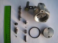
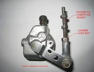
If you look closer at the lower ball socket it is marked with R, which means rechts (right) and normal threads. If you look closer at the upper lock nut you see a vertical slotted mark on it, which indicates that it is the links (left) threaded end of the adjustment rod. Post #53, image #1

The car has to rest on the wheels in normal position when you do the adjustment. So if the car has been on a lift or jacked up partly to get access for work, it has to be lowered and rolled back and forth to normalise the wheel position so the car is resting normally. I prefer to use a bridge lift for this.

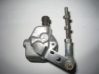
- hold the 10mm key on the welded nut in center of the adj.rod
- losen the locking nuts on both ball sockets, and turn them towards center so they clear
- start the car and let it idle
- to lower the car you turn the adj.rod clockwise, which means you extend the free length
- turn until you notice a movement on the car, it is no danger with this and you can turn as fast or slow as you like
- but you need a ruler or something to measure the movement against a reference point on the car, while you adjust
- if you don't notice any lowering, turn the adj.rod the other way to see if the car elevates
- then adjust it down again
- at the point where the lowering stops, is the car resting on the springs

You may risk to extend the adj.rod too far so it comes free from the ball sockets, but nothing happens of that reason. But it will be some fiddling to get it to engage in both ball sockets at the same time again. So calm down, take a coffee, concentrate, and no kids, pets or woman around.

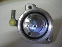
If you end up with a wanted height that leave the car resting on the springs, which I think you may do with new H&R springs, you have to adjust the rod so the lever on the valve is in neutral position, shown in post #53, image #8, last photo. The lever is aligning with a hole in the valve, and you can see I have used a screw on the photo to keep it there during assembly.

Then it is out for just a short test drive so it settles a bit, followed by checking the ride height.

If you are lowering the car 15-20mm, I would recommend to loosen the inner bolts on the LCA to release the twist in the bushings.

Happy wrenching! :-)

Cheers
-a-
 
Last edited:
Ken is lowering a 124 wagon, not an E500E, so his experience will be a bit different. I'm assuming he has the H&R wagon springs.

That's what I meant, should've noted it. On a wagon, when side by side with another wagon, his H&Rs were lower than my Sportline and I was at the lowest the springs were allowing. Both on one dot pads.
 
hi all

i looking the need part A1243281240 SLS.

please advise if you can help me. thanks you
 

Attachments

  • 1540545998896.jpg
    1540545998896.jpg
    261 KB · Views: 15
I just need a clarification and don't want to start a new thread, this seems to be the right one to resurrect. I have my car up in the air with a lot of bolts in rear suspension loosen, removed, replaced etc. On top of that I'm changing H&R springs back to stock so height adjustment will be a must. Which bolts from photo below should be loosen then re-tighten once the car is on the ground prior to adjustment - red, green or both?
 

Attachments

  • bolt.JPG
    bolt.JPG
    443.4 KB · Views: 44
I can only speak for the red one. Definitely get your axle level before tightening this one. Either by putting the car on the ground or by raising the control arm while the car is on a lift. I used the latter method and it gave me plenty of room to swing the torque wrench.
 
Red, not green.

As noted above, don't tighten the red nut without the rear wheel in the "ready to drive" position. This may not be possible in the air without a spring compressor, as if you raise it up, the car starts to lift off whatever was supporting the chassis. Even on a lift, the car starts to go up in the air before the wheel is in the correct position.

I lower the car on to thick wood blocks so you have room to slide underneath, then add weight in the trunk as needed to get the rear fully settled, then tighten the nut.
 
You can also do it with the rear backed up on a pair of ramps, for clearance.
Yes - if you have ramps, this would be ideal. Again, some weight may be required in the trunk to get the level correct.

Which reminds me, I really need to get a pair of ramps!!

:rugby:
 
Yes - if you have ramps, this would be ideal. Again, some weight may be required in the trunk to get the level correct.

Which reminds me, I really need to get a pair of ramps!!

:rugby:
These have worked out excellently for me:


They also make a modestly cheaper set with less weight capacity:

 
Driving the 92' yesterday and heard a loud pop while entering a parking lot.
The adjustment rod bushings had hardened in the sockets broke and popped off the SLS. The rear end rose to maximum height.
Is this rod NLA? Does anyone have a part number?
It is #41 in the schematic.

dibujo3-jpg.4208
 
Last edited:
Hi Trae,

The number is 124 320 09 89. It is definitely avaialble, $30 list, around $22 discounted. I would get a couple of extras, as they do wear out, for your other cars. I got a spare for my E500 a couple of years ago.
 
The OE price of the ”unserviceable” level controller has gone north of 1000 €/$. Asking price for used ones is up to 500.

As 500AMM mentions in his excellent writeup, one of the main problems is clog-up of the tiny sintered filter (3q) in piston assembly. A cheap bodger fix is to drill a hole through it e.g. 1,5 mm carefully, not damaging the check valve under it.

AFAIK the shaft O-rings are inaccessible - if leaking, the valve is junk. Other seals can be replaced but there is no repair kit available like for the earlier square SLS valve type.

THX for the very informative thread!
 
Tacking this question on here for future benefit.

Has anyone used the second inboard hole on the SLS connecting arm (the arm on the valve itself)? It is in more vertical alignment with the sway bar arm and I'm wondering what the small decrease in leverage will do. Seems to me the change would make the system more sensitive. Just curious as I'm reassembling this after compehensive work at the rear.
Drew,

Per the FSM is bore "a" on the pivot used for the W201.

SLS pivot bores.jpg

I think the same SLS valve is used on the 210 models having a different linkage, and it appears that bore "a" is utilized as a guide hole for the linkage.

1728288972664.png
 
Last edited:
Hi.

I recommend you take off the connecting rod and clean & lubricate, that should save it. At the same time you'll be able to check that the SLS really works. Place the car on a "bridge lift", resting on the wheels, leave the car idling, and move the lever on the SLS-valve and notice the movement of the car. The car moves quite slowely. When you move the lever down the car also goes down, and vice versa to elevate.

I also recommend to bleed some air from the system at the same time. It's a bleeding screw on top of the SLS-valve, and you also bleed at the hose terminals up at the hydropneumatic struts. If you elevate the car to max hight first, you get easy access to the hose terminals on the struts. Keep in mind that the system is pressurized, so you don't need to open much to get the mix of air and oil out quite fast. It is a messy job.

Cheers
Any recommendations on taking off the connecting rods. Does one just pop them off the ends. Mine looks mucky.
 

Attachments

  • IMG_9018.jpeg
    IMG_9018.jpeg
    1.1 MB · Views: 7
Any recommendations on taking off the connecting rods. Does one just pop them off the ends. Mine looks mucky.
Don't pop the ends! To remove the turnbuckle, you remove the 10mm nut on each end.

If only adjusting length, the turnbuckle does not need to be removed. See annotated photo in post #61 above.

To lower the rear, adjust the turnbuckle LONGER.
To raise the rear, adjust the turnbuckle SHORTER.

:klink:
 
Each end of the link has an 8mm flat that is held with a wrench while you remove the 10mm nuts Dave referenced. This requires a very thin wrench like an ignition wrench. You might hope as everyone does that the nut will come off without holding the flat. It won't. The nuts are nylock.

Disclaimer: the flats might be 9mm.

Moderator edit: Flats are confirmed to be 8mm. This is only needed to remove the link from the car, not to adjust it.
 
Last edited by a moderator:

Who has viewed this thread (Total: 5) View details

Who has watched this thread (Total: 2) View details

Back
Top