• Hi Guest !

    Welcome to the 500Eboard forum.

    Since its founding in late 2008, 500Eboard has become the leading resource on the Internet for all things related to the Mercedes-Benz 500E and E500. In recent years, we have also expanded to include the 400E and E420 models, which are directly related to the 500E/E500.

    We invite you to browse and take advantage of the information and resources here on the site. If you find helpful information, please register for full membership, and you'll find even more resources available. Feel free to ask questions, and make liberal use of the "Search" function to find answers.

    We hope you will become an active contributor to the community!

    Sincerely,
    500Eboard Management

RESTO PROJECT: M119 / W124 / E500 Engine Top-End Refresh

gerryvz

Site Honcho
Staff member
What with the current "self quarantine" imposed, I thought it a good time to begin a very long-standing project -- the complete refresh and cleaning of the top end of my M119 engine. Note that my E500 has 143K miles on it.

There was ZERO issue with running, other than the following small issues:
  1. a small but annoying engine oil leak from the valve cover, resulting in oil dropping onto the exhaust manifold and smelling
  2. a persistent set of two codes being thrown over the past few years -- an EGR code and an "air injection inop" code, resulting in a CHECK ENGINE light being lit (and recurring after being cleared)
  3. A leaking front crankshaft seal, resulting in a small but persistent few drops of oil on the floor after every drive of the car.
The black rubber air intake hoses on my car had been replaced with new factory hoses around 2005, when I lived in Portland, Oregon. This was because the old hoses at that time had becom fossilized and hard.

The caps and rotors had last been replaced around 2005, also when I lived in Portland. I did not notice any running issues due to the caps and rotors, since that time.

Over the past few years, I'd decided to do a complete refresh of the top end of the engine -- particularly all of the 'soft parts' -- because much of it was original, and now 26 years old.

Generally, the scope of the job is as follows:
  • Replace all vacuum lines in the upper engine area
  • Replace rubber intake air tubes (if needed)
  • Replace suspected lazy thermostat with new Wahler unit
  • Proactively rebuild original ETA wiring
  • Replace soft parts at intake manifold -- fuel injector seals, intake manifold gaskets and seals, etc.
  • Replace upper timing chain rails
  • Clean out likely clogged EGR tube inside intake manifold
  • Separate and have halves of intake manifold hot-tanked
  • Replace transmission cooling hoses
  • Replace heater hoses at back of engine
  • Replace smog pump hoses
  • Replace front crankshaft seal
  • Replace two ignition coils
  • Replace ceramic resistor
  • Inspect distributor caps, rotors, and insulators and replace if needed
  • Inspect other plastic and soft parts and replace if needed
  • Replace cracked/broken/missing plastic conduit in engine compartment
  • Replace cam covers with red covers I had powder-coated two years ago
  • Replace very crunchy hood pad with new hood pad
  • Change transmission fluid, filter and pan gasket
  • Perform any other maintenance and repair underhood as needed
So, as you can see, this is a very long job that is going to take methodical process and lots of time to complete. Who knows what I will find along the way? This will be a running tally as I work through everything. I am expecting this to take a couple of months -- some of the time gating on how quickly I can obtain the needed parts from MB and other sources. I will maintain a tally of all parts that I find that require replacing or repair, along with the costs and sources for said parts. I will only be going with quality aftermarket parts (i.e. Elring for gaskets), but otherwise will stick with factory MB parts.

So ... let's get started. My first night in the shop consisted of around 90 minutes of time, mainly taking apart the main top elements in the engine compartment, to expose other parts that will be the subject of actual repairs.

First off, here's an overview of the engine compartment. Typical M119 / W124 engine -- looks good, runs great. No complaints. Why am I embarking on this long journey, again !?!?!
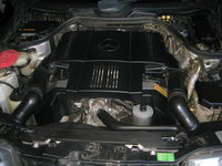
IMG_8579.jpeg


The first step, of course, is to DISCONNECT THE BATTERY in the trunk. Remove the positive or negative terminal from the battery, so that no power goes to the car's systems.

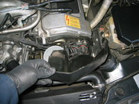
Next, you need to remove the plastic airbox and decorative cladding on the top of the engine. Remove the two "zoom tubes" that connect the air intakes to the airbox, and then remove the airbox as a unit. Set everything aside for safekeeping.
IMG_8580.jpeg IMG_8581.jpeg IMG_8582.jpeg IMG_8583.jpeg


Next up, remove the two plastic covers that hide the caps and rotors. These should generally just pop off with a gentle flexing past the integrated clips.
IMG_8584.jpeg IMG_8585.jpeg IMG_8586.jpeg IMG_8587.jpeg


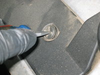
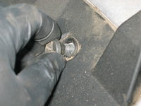
From there, remove the two covers that hide the spark plug wires on each bank of the engine. A large flat-blade screwdriver (I used a "stubby") is excellent for getting a bite on the large plastic bolts that hold this cover to the top of the valve covers. Unscrew the bolts, and gently lift the cover off.
IMG_8588.jpeg IMG_8589.jpeg IMG_8590.jpeg IMG_8591.jpeg


Then, do the same on the other side.
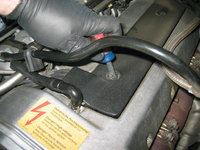
IMG_8592.jpeg IMG_8593.jpeg


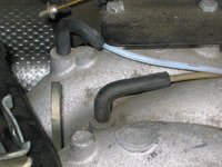
Upon removing the airbox and the covers for the spark plugs and wires, I came across the first red flag of the job -- a visually degraded throttle cable in the back part of the engine. Touching this throttle cable, pieces of the white adjusting screw flaked off, and you can also see literally broken pieces of plastic as part of the adjusting mechanism. So, add this to the list as the FIRST part that will require replacement. Fortunately, I believe I have one already in my parts stock (which I've had for probably 15 years there). And coincidentally, I just sent off a second spare cable YESTERDAY to one of our forum members.
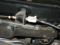
IMG_8594.jpeg IMG_8595.jpeg IMG_8596.jpeg

In the last photo above, you can also see the degradation in the whitened plastic grommet, just to the right of the spring in the photo. This is a $2.50 part from MB (and I believe also comes with a new throttle cable) -- and I believe that one of our members recently had this part fail, causing running issues. Since this part is so cheap, and important to the running of the vehicle, I recommend that you have a spare or two in your parts stock. I have FOUR spares, plus the one that is already installed on the throttle cable that I'll be replacing this one with.


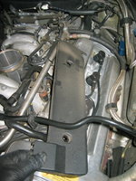
So, with the plastic covers removed from the engine, here's what the "bare" M119 looks like, just before we start diving in to remove more parts.
IMG_8597.jpeg


It's time for the next stage, which is the removal of the distributor components -- namely the distributor caps, rotors, brackets and insulators. We'll remove and then carefully inspect their condition in a few minutes. Let's dive into exposing them for removal, for now.

Using a pair of special "spark plug" pliers, grasp each ignition connector at the cap, twist it slightly (1/8 of a turn should break it loose), and pull it straight off of the terminal on the distributor cap. You can do this with your fingers, but having a pair of special pliers to do this makes the job about 80% easier (and easier for installation, eventually, too). Remove all four of the connectors for the cylinders on each cap, plus the central coil wire connector.
IMG_8598.jpeg IMG_8599.jpeg IMG_8601.jpeg IMG_8600.jpeg


You may want to use a "Sharpie" or other pen and label each distributor cap's terminal as to the plug wire cylinder number that it corresponds to. I did this for the passenger side, and then didn't bother to do it for the driver's side, because of THIS......
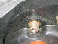
IMG_8602.jpeg

Yes, that is what you think it is -- a CRACKED distributor cap ! Another part for the "replacement" list -- although cap/rotor/insulator replacement was going to be included in this job anyway.

So, the next step is to remove the distributor caps. You need a 5mm Allen socket or Allen key to do this. DO NOT use the "ball" end of an Allen key for cap or rotor removal -- ONLY a straight end that is not beveled. This will ensure that the bolts do not get stripped out. The next few photos show the removal of the caps, using a couple of different tools. A 5mm "swivel" Allen socket comes in handy for the bottom bolts on the caps, which are difficult to reach. These are the SAME 5mm swivel sockets that are used for removal of the back bolts on the valve covers, so are a worthwhile investment.
IMG_8603.jpeg IMG_8604.jpeg IMG_8605.jpeg


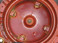
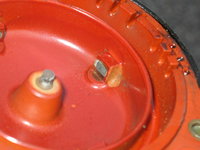
After the three bolts on each cap are removed, pull the cap off and inspect it. Here's what I found on the inside of my passenger-side cap (remember, these had been last replaced around 2006, so nearly 14 years ago!):
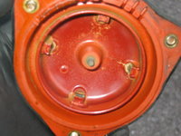
IMG_8606.jpeg IMG_8607.jpeg IMG_8608.jpeg IMG_8616.jpeg IMG_8609.jpeg

Not horrible, but not that great eather. You can see a couple of carbon tracks between the center (coil) piece and two of the contacts. This would result in some misfiring or other minor hiccups in running, though to be honest I never really saw or felt any running problems. BUT, the caps could stand for replacement. Still, not bad for ~14 years old.

Here is a view of things with the cap removed:
IMG_8610.jpeg


Earlier, I forgot to remove two plastic pieces, so did it now -- the two plastic air intake pieces that comprise the back-side of the headlights, which the zoom tubes connect to. These lift straight up and out. Keep these pieces safe, as they are both NLA from MB.
IMG_8613.jpeg


More inspection of the cap from the driver's side. Note that it is aftermarket Bosch, October 2005 production date. Not as bad as the passenger side -- not much in the way of arc traces.
IMG_8614.jpeg IMG_8615.jpeg IMG_8616.jpeg


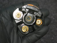
Now it's time to remove the rotors, and the brackets they attach to. The rotors attach via three 3mm bolts, and the brackets attach via a single, 5mm central bolt. It is IMPERATIVE again that you NOT use beveled or rounded Allen keys to remove the rotor and bracket bolts. ONLY use straight-edged Allen keys and Allen sockets to avoid stripping out these bolts.
IMG_8617.jpeg IMG_8618.jpeg IMG_8620.jpeg IMG_8621.jpeg IMG_8622.jpeg IMG_8619.jpeg


After careful removal and inspection of the rotors, it's time to remove the 5mm bolt holding the rotor bracket on.
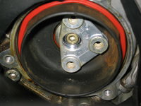
IMG_8623.jpeg IMG_8624.jpeg IMG_8626.jpeg IMG_8627.jpeg


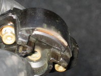
After the bracket comes off, the insulators will come right off of the cylinder head. Time to inspect them carefully. These were the original, black Bosch Doduco insulators that my car came with. You can see that they do not have a lot of wetness or condensation on them, thankfully. The orange rubber seal on the front side is very smashed and flattened down.
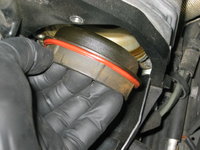
IMG_8628.jpeg IMG_8629.jpeg IMG_8631.jpeg IMG_8632.jpeg


After removal of the insulators, you can see the actual end of the cylinder heads. A couple of observations here: 1) some oil leakage is observed on both sides. This tells me that there is a modest (not severe) oil leak at the cam seals, which will necessitate replacing both sides' cam seals. This shouldn't be too big of a deal, but yet another part to place on the order list.
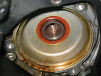
IMG_8630.jpeg IMG_8634.jpeg IMG_8635.jpeg IMG_8633.jpeg


Next up, it's time to remove the plastic pieces that are bolted to the ends of the cylinder heads, that surround the distributor caps. These are extremely thin pieces of plastic, and can get quite brittle. I found that, while mine came off OK, on one side, two tabs cracked off, and on the other side, one small crack developed. These are cheap parts (around $15 apiece, discounted, from MB), and so I will place them on my parts order list -- although I will keep the "old" ones as they are in good enough condition.

Each of these plastic pieces is held on by three 5mm Allen bolts. Two of the bolts on each side are difficult to get at, and are best reached with a long Allen key, or your 5mm "swivel" socket using a 1/4" drive and an extension. The bottom-most bolts, you have to pretty much remove by "feel".
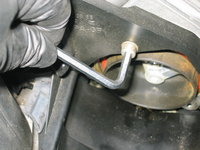
IMG_8625.jpeg


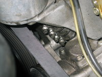
It had been a few years since my tandem pump refirbishment and the replacement of the "short hose" between the reservoir and tandem pump, so it seemed like an opportune time to see how the short hose was holding up. You can see here a couple of views of the short hose with the four clamps I'd placed on it. Some modest seeping of fluid, but no outright leaks. I will clean up the area and snug down each of the clamps, but otherwise things seemed more or less OK. It actually looks a bit worse in the photos than it did to my naked eye. A couple of shots of brake cleaner will make short work of this area, when the timne comes....
IMG_8636.jpeg IMG_8637.jpeg


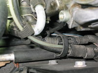
Here is a shot of the vacuum wire routing in the area near the tandem pump. You can see the corrugated wire conduit, most of which has flaked off and disappeared. I will be replacing all of this conduit at the time of reassembly, with new conduit that is hopefully heat resistant. This should clean things up and restore a more factory appearance to things.
IMG_8638.jpeg


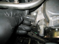
The next phase of the job entails removing all of the connectors on the intake manifold that pertain to the upper wiring harness. I'd had my harness replaced back around 2005, so I was in good shape with it, and a visual inspection of the end connectors confirmed that it is holding up very well. The next photos are of the removal of various connectors at sensors on the cylinder head and intake manifold. Several connectors cracked from heat, so new parts to replace them will be ordered. They are very inexpensive to replace.
IMG_8639.jpeg IMG_8640.jpeg IMG_8641.jpeg IMG_8642.jpeg IMG_8643.jpeg IMG_8644.jpeg IMG_8645.jpeg IMG_8646.jpeg IMG_8647.jpeg IMG_8648.jpegIMG_8649.jpeg IMG_8650.jpeg IMG_8652.jpeg


Next up was removal of the EGR valve, which sits atop the intake manifold. This is held on by three 5mm Allen bolts, and there is a gasket underneath the valve that will require replacement upon reassembly. There is a vacuum connection in the area -- both to the EGR valve itself, and to a nipple atop the intake manifold. The following photos show the removal of these vacuum connectors, and of the EGR valve itself.
IMG_8653.jpeg IMG_8654.jpeg IMG_8655.jpeg IMG_8656.jpeg


The next thing to do is to remove all eight spark plug wires, plus the two coil wires, from the engine compartment. This will make more room for the future steps.
IMG_8657.jpeg


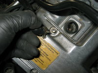
Next up, you need to begin removing the rubber air intake hoses from their fittings on the valve covers. Just lift them up -- you'll remove the actual hose assembly in a few minutes.
IMG_8658.jpeg


Here's what the engine looks like with the plug wires removed.
IMG_8659.jpeg


In the process of removing the vacuum connectors from the EGR valve and nearby nipple on the intake, one of the vacuum lines literally pulled out in my hand. It had already cracked (and you can see a short, newer section of vacuum line from a repair I'd done when I lived in Texas). This is very likely the cause of the "EGR inoperative" failure that I'd been reciving CHECK ENGINE lights for, over the past few years. The vacuum line was completely cracked off between the EGR valve and the smog pump area where it led to. So this will need, obviously, to be replaced with new vacuum line.
IMG_8660.jpeg


Here is the removal of various bolts that hold the plastic frame for the upper wiring harness to the top of the intake manifold. These are 5mm and 6mm Allen bolts, and are quite easily despatched. At this point, you should also unclip each of the eight fuel injector connectors by squeezing the metal wires together at each injector, and pulling the connector straight off of the injector.
IMG_8661.jpeg IMG_8662.jpeg IMG_8663.jpeg


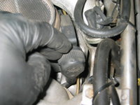
Here you can see the thick plastic connector for the upper wiring harness to the MAF. Twist the MAF wire connector and work it up and out of the way.
IMG_8664.jpeg IMG_8665.jpeg


At this point, with all of the upper wiring harness connectors removed, you can lift the upper harness out of the way and fold back over the CAN box area.
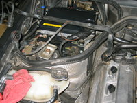
IMG_8666.jpeg


Next up, you need to disconnect the vacuum line that goes from the intake manifold to the brake booster. This is a semi-flexible plastic line, and it may or may not still be good. Use a 17mm open-end wrench, along with a 19mm wrench, together to loosen the connector. Unscrew the connector and do your best to move the vacuum line out of the way.
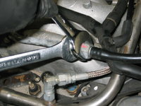
IMG_8667.jpeg IMG_8668.jpeg


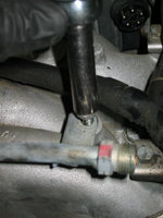
Next up, you will need to begin disassembly and removal of the fuel rail. It is held onto the top of the intake manifold by a bunch of 10mm bolts Here I remove a couple of them, but will continue the process in the next part of this HOW-TO.
IMG_8669.jpeg IMG_8670.jpeg


Next up is the removal of the intake air rubber hose system from the top of the intake manifold. Here you can see me clipping a zip tie that had been placed between one of the hoses and the fuel rail, to keep them together. This had been done when the nitrous-oxide system had been installed on my car in the 2004-2005 time frame. I will replace this zip tie upon reassembly, but for now it is one of the last hurdles to removing the intake air hoses. Note the gummy dirt on the outside of the hoses in the third photo below -- likely because of the vapor from the intake that traveled through them, attracting dirt and detritus.
IMG_8671.jpeg IMG_8672.jpeg IMG_8673.jpeg


Finally, removal of the complete air hose system from the top of the engine. All of my hoses, which were all quite still flexible, were in good condition. I have replacements for all of them, and will probably use them on the rebuild.
IMG_8674.jpeg


And lastly, foreshadowing the next phase of the job ... the MAF and its ring clamp bolt.
IMG_8675.jpeg

Stay tuned for the next installment of this HOW-TO, where I'll be showing the removal of the fuel rail and fuel injectors, removal of the MAF, and then removal of the intake manifold "stack" itself.

Thanks for watching, so far.
 
Here you can see me clipping a zip tie that had been placed between one of the hoses and the fuel rail, to keep them together. This had been done when the nitrous-oxide system had been installed on my car in the 2004-2005 time frame.
Gerry, why did you remove the NOS sytem?

:nos:
 
I didn't remove the Nitrous system. It's still 100% still there. I was just referring to the fact that the zip tie had been installed back in 2004-2005. As opposed to being installed by someone now.
 
Hi Gerry, this is all good and looking forward to the DIY!

I would suggest that whilst you are doing a Top End refresh, pop the heads off and have them refurbished along with new Valve Oil Stem seals and make a proper job of it! Seriously they will be very tired by now and for me this is the only way to do it on a nearly 30 year old engine..... but I am a lunatic so maybe pay no attention :)

PS there are EGR tracts from the timing cover which you can only clean with the heads off too. So dont expect to be able to fully clean the EGR tracts with the top end tickle planned :hornets:

Unsurprisingly EGR cleaner in an aerosol can with a small selection of stiff pipe cleaner brushes is a must for getting the caked up junk out of there. Nothing else would shift it for me except specialist EGR cleaner so get a few cans if you dont already have some in stock
 
I'm not going to bother with the cylinder heads at this point. I definitely would if there were head gasket leakage, burning of oil, or another issue (like I had with my M117). But the M119 doesn't have these issues, and I've no doubt that the heads are just fine (perhaps a bit coked up, but not really detrimentally). I'll of course be able to see more when I get the intake manifold removed.

Yep, am aware of the EGR passages in the heads that can only be reached by removing them. Still not enough to make me pull them :)

The intake manifold halves will be hot-tanked by a local machine shop.

I'm looking forward to what EGR obstructions I find.
 
Well, I spent about 2 hours 15 minutes in the shop (taking my time, as I am wont to do with these things), and continued on and made some decent disassembly progress. Following is an overview of what I did, early this afternoon.


First, upon @gsxr's advice, I took a couple of more close-up photos to reveal things around the cam seals and cam solenoid area. It appears that on both sides, there is not only some very modest oil leakage from the cam seals, but also from the cam solenoids on both sides. These are not bad or major leaks, but they will need to be taken care of. This process of refurbishment will be addressed in the remedial section of this HOW-TO.
IMG_8676.jpeg IMG_8677.jpeg


After scoping out the cam area, I then turned my attention to continuing the disassembly process. Specifically, I removed the two front bolts (parallel to the ground, on the front of the manifold) that secure the lower part of the "X" tray, for the spark plug wires. The passenger side bolt is a 6mm Allen bolt; the driver's side is a 13mm normal bolt. Both were despatched with efficiency, per the below photos.
IMG_8678.jpeg IMG_8679.jpeg IMG_8680.jpeg


I also loosened the two bolts on the top of the intake manifold (driver's side shown below), that secure the top ends of the "X" tray to the engine. Again, pretty quick removal. And again, both 6mm Allen bolts.
IMG_8681.jpeg IMG_8682.jpeg


The next couple of photos are mainly for my own reference, in terms of the routing of the vacuum lines from the EZL and vapor recirculation valve (both on the driver's side inner fender-wall) through the intake manifold halves and back to the manifold itself and the ETA, respectively. You can see that the corrugated plastic sheathing that surrounds these vacuum lines is crumbling and almost gone; I will be replacing not only both of these lines and their connectors, but also the sheathing itself for a hopefully factory appearance in the end.
IMG_8683.jpeg IMG_8684.jpeg


Next step was to use a 13mm open-end wrench, to remove the fuel line for the nitrous-oxide system where it attaches to the fuel rail. On pretty much all of your cars, this is going to be the Schrader-style fuel system pressure port, so you can pretty much ignore this step. This is specific to the very few cars out there that have the BergWerks Nitrous-Oxide System installed.
IMG_8685.jpeg IMG_8686.jpeg


The next few photos are mainly reference photos for the BergWerks nitrous system fuel piping and wiring. Again, nothing for you folks to worry about.
IMG_8687.jpeg IMG_8688.jpeg IMG_8689.jpeg IMG_8690.jpeg IMG_8691.jpeg


Removing and moving the BergWerks nitrous piping out of the way for near-term fuel rail removal.
IMG_8692.jpeg


Removing the six bolts that hold the fuel rail to the top of the intake manifold. This is pretty straightforward.
IMG_8693.jpeg IMG_8694.jpeg


Next, remove the clips that secure the top of each fuel injector to the its port on the fuel rail. You can loosen these clips with your fingers, or a small flat-blade screwdriver, and then slide them out.
IMG_8695.jpeg IMG_8696.jpeg


Here are a few views of the fuel injectors, showing position and orientation of the clips, for reassembly.
IMG_8697.jpeg IMG_8698.jpeg IMG_8699.jpeg IMG_8700.jpeg


These are reference photos that show the fuel line area at the back of the engine, mainly for reassembly reference. In the first photo below, I have removed the double-clip that hold the fuel feed and fuel return lines apart, but secure them together. You can see a bit of chafing on the fuel feed line from the clip. Both of these lines are no longer available from MB.
IMG_8701.jpeg IMG_8702.jpeg


With a 17mm open-end wrench, and placing a towel underneath the connection, loosen and remove the fuel feed line from the fuel rail. It should leak too much fuel, and the towel underneath it should soak up the fuel. Similarly, with the same 17mm wrench, remove the fuel return line, which is further aft on the fuel rail.
IMG_8703.jpeg


Pull the crankcase vapor hose straight up and off of the rear of the passenger side valve cover.
IMG_8704.jpeg


Reference photo for reassembly of the fuel rail and fuel pressure regulator area of the fuel rail.
IMG_8705.jpeg


Here I quickly removed a vacuum connection on the top of the intake manifold.
IMG_8706.jpeg


In these next few photos, I used my handy fuel line plugs to screw into the ends of the fuel feed and return lines. This blocks them and helps keep dirt out, and vapors from escaping from the lines.
IMG_8707.jpeg IMG_8708.jpeg IMG_8709.jpeg


Once the fuel lines are secured and made safe, carefully lift the fuel rail off of the top of the engine. It will require a bit of steady upward pressure, and you may or may not have an injector or two come out of the manifold, remaining attached to the fuel rail. However, in most cases, as with my engine, the injectors (well, 7 out of 8 of them!) will stay embedded in the intake manifold.
IMG_8710.jpeg


Next, to remove the fuel rail from the engine compartment, you will need to remove the ETA cable from its connector. IT IS ACTUALLY ADVISABLE TO DO THIS BEFORE you lift the fuel rail. I did this by lifting the late-model connector's flip-up securing panel, and then pulling the connector straight out, as shown in the next three photos.
IMG_8711.jpeg IMG_8712.jpeg IMG_8713.jpeg


The next part of the ETA cable removal process is a bit of a dance, because you need to get the ETA connector plug THROUGH the inner firewall, and into the engine compartment. I did this by unscrewing one of the inner firewall plastic screws (left side of photo below) and very slightly with a large screwdriver, moving the inner firewall metal about 1/4" -- just enough to allow the ETA connector to slide through the slot between the windshield wiper rain tray, and the inner firewall metal panel. It worked -- but just barely. Otherwise, I would have had to remove the center section of the windshield wiper rain tray -- something I did not want to do at that moment !! I got it, though.
IMG_8714.jpeg


Here you can see two views of the intake manifold area, with the seven injectors in place immediately after fuel rail removal.
IMG_8715.jpeg IMG_8716.jpeg


Remove each injector from the manifold by pulling straight up on it. It may take some force. It also may or may not leave the injector's two sealing rings (green and black, shown in the image below) still in the manifold port, or the injector may come out with them attached. I had about four of five of my injectors come out with the pintle cap on the end of the injector intact and present; the other injectors had no pintle cap when they came out of the manifold. So, I will need to search for them in the manifold/combustion chamber after I remove the intake manifold.
IMG_8717.jpeg


After the fuel rail is removed, you can then remove the plastic "X" tray that routes the ignition wires. Below are views of the fuel rail, and the "X" tray as removed from the engine.
IMG_8718.jpeg IMG_8719.jpeg IMG_8720.jpeg


Next, I decided to remove the gasket for the EGR valve, which was still attached to the top of the intake manifold. A quick pry with a thin flat-blade screwdriver took care of it.
IMG_8721.jpeg IMG_8722.jpeg IMG_8723.jpeg


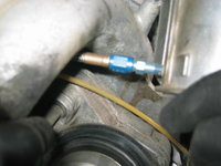
Next up, it was time to remove the MAF from the ETA. Using two long flat-blade and Philips head screwdrivers (alternating between them as needed), I was able to loosen the ring clamp that secures the bottom of the MAF to the black rubber gasket that fits between the ETA and the MAF. This upper clamp's bolt was accessible from the passenger side of the engine. After it was loosened, I was able to work the MAF back and forth and prise it free with some force. A bit of prying against the hardened rubber MAF gasket also helped work it free. In the third photo below, you can see the nitrous-oxide injection line, where it is tapped into the back of the MAF. I used an 11mm wrench to remove the line from its fitting on the MAF. Most all of you, of course, won't have to worry about this.
IMG_8724.jpeg IMG_8725.jpeg IMG_8727.jpeg IMG_8728.jpeg


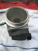
A few views of the MAF, removed from the car. As you can see, it is fairly clean and in great condition overall. The top and bottom screens are perfect.
IMG_8729.jpeg IMG_8730.jpeg IMG_8731.jpeg IMG_8732.jpeg

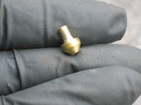
This little brass fitting fits into the end of the nitrous-oxide line, and helps focus the flow of nitrous into the intake air stream passing by the MAF. Notice that the nitrous nozzle is plumbed into the MAF **after** the hot-wire air measurement point, not before it. Also note the date on my ETA label -- 93M07 -- July, 1993. Yep .. this is the original ETA for the car.
IMG_8734.jpeg IMG_8735.jpeg IMG_8736.jpeg


Remove the last couple of vacuum connections on the back of the intake manifold. One of these connections goes to the transmission; the other one goes to the vacuum distributor hear the brake booster on the other side of the inner engine-bay firewall. You can see that the vacuum line leading to the transmission has been replaced and is not original.
IMG_8737.jpeg


Next up, it's time to focus on the fuel rail. Using a small hooked tool, remove each of the remaining rubber o-rings that secure the top side of each fuel injector to the fuel rail. When you remove the rail from the engine, and the injectors stay in the intake manifold, these o-rings remain in the fuel rail ports. Pick these o-rings out and throw them away, as you will be replacing them with new o-rings.
IMG_8739.jpeg IMG_8740.jpeg IMG_8741.jpeg IMG_8742.jpeg


Before you do, though, take a close look at the o-rings. Here, on one of mine (most all of them were like this) ... you can see some modest cracking in the o-ring. These would not have lasted too many more years or miles before they would have leaked and required replaced. Not to mention, made the car run like crap.
IMG_8743.jpeg IMG_8744.jpeg


And just to finish out the day's activities .... Here are a couple of views of the engine, partially disassembled, as it now stands.
IMG_8745.jpeg IMG_8746.jpeg


The next steps will be to drain the coolant down, so that as much coolant is removed from the intake manifold as possible. This is in preparation for the removal of the intake manifold. There will be two coolant connections on the manifold -- one at the front of the manifold, and the other to a heater hose at the rear (which goes through the inner firewall).

So, this is where we will pick up when we return. The next step will be the removal of the intake manifold assembly itself, and then its disassembly.

Thanks for your interest !!
 
Lookin' good, Gerry. Tip on the coolant: Use the engine block coolant drains, especially since you are changing the thermostat. If you don't drain the block, you'll get a coolant bath when you take out the old t-stat. BT, DT...

:duck:
 
Fun stuff Honch. Really important issue that is overlooked when I was a novice with this. The black NLA headlamp cover on the DS, be completely sure that you install that temp sensor back into the plastic. As soon as you turn the key, the CEL will come on without it and your heart will sink. (Ask me how I knew that pain after a similar job upon ownership) A huge excitement killer then you scramble your brain wondering if you dropped something down the spark plug hole!
 
Here is the list of identified parts that I'll be replacing, at this early stage in the process. I have zero doubt that this list will be dramatically expanding in the coming weeks, as I get further into the job and determine additional parts that require replacing.

For future additions to this list, I will color code the batch entries I make that expand the list.

MB Part NumberPart Description
Quantity
StatusPriceNotesPhoto
119 158 06 85Suppressor Housing, Left
1​
Available$14.43Black plastic plate that surrounds distributor cap.
119 158 05 85Suppressor Housing, Right
1​
Available$15.54Black plastic plate that surrounds distributor cap.
012 545 04 28Pin Bushing Housing
10​
Available$1.48Two-pin connector housings to replace cracked ones. Ordering extras.
117 140 02 65Connector, Intake Manifold
8​
Available$6.66Rubber donut rings that connect two halves of intake manifold. Shared with M117.
019 997 13 48Fuel Injector O-ring
16​
Available$3.63O-rings that seal fuel rail to injector and injector to intake manifold. 2 per injector.
119 142 08 80EGR Valve Gasket
1​
Available$2.37Gasket between EGR valve and intake manifold. Likely will come as part of intake manifold gasket kit.
119 141 12 80ETA Gasket
1​
Available$1.48Gasket between ETA and intake manifold. Already have in my parts stock.
119 141 01 67Air Duct
1​
Available$18.13Rubber boot between top of ETA and bottom of MAF. Already have in my parts stock.
119 142 01 80Manifold Gasket
2​
Available$1.78Small gaskets between ends of EGR pipe and ETA and intake manifold.
018 997 79 47Sealing Ring, Camshaft
2​
Available$11.84Camshaft seals
119 051 00 77Magnetic Sensor
2​
Available$80.66Cam solenoid
111-051-00-43Armature
2​
Available$7.03Cam solenoid armature
119 158 01 02Distributor Cap
2​
Avaialble$61.09Beru distributor cap. Will purchase via aftermarket.
119 158 01 88Insulator
2​
Available$57.70Bosch distributor insulator, behind cap and rotor. Will purchase via aftermarket.
119 158 03 31Distributor Rotor
2​
Available$32.50Doduco distributor rotor. Will purchase via aftermarket.
003 997 72 90Clamp
2​
Available$1.11
124 832 65 93Hose
1​
Available$86.58Heater hose from back of intake manifold to heater. Proactive replacement due to location/difficulty to get at.
 
Today I spent around 3 hours in the shop, doing some incremental work on things. I did achieve my goal of removing the intake manifold from the engine, and disassembling it.

Around 45 minutes after I started, I had a visitor drop by my shop, our own @linjam. He came by to pick up a couple of items (a 500E repop emblem and a 124 ambient temp gauge) that he had bought from me a couple of months ago.

What follows is my saga from today.

Upon recommendation of @gsxr, I drained both the radiator and the driver's side of the block before I started. This was easy enough, and involved the following steps:

1) Remove the under-engine cladding piece, by removing its 8mm screws that hold it to the underside of the engine compartment

2) Loosen the coolant overflow tank cap and leave it setting loosely on top of the coolant overflow tank.

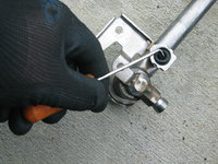
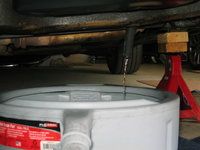
3) Drain the radiator using the pet-cock at the passenger-side bottom corner. I used a "stubby" screwdriver, per below, to loosen and remove the pet-cock to let the radiator drain into a large drain pan.

4) Loosen one (or both) of the block drains, and drain it into a pan.

5) Re-tighten the block drain(s) that you loosened, so that you don't forget to do it in the future.

Here are a couple of photos of the radiator pet-cock, and me beginning to loosen it with my stubby flat-blade screwdriver.
IMG_8747.jpeg IMG_8748.jpeg


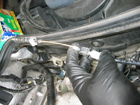
While the radiator was draining, I removed the very sad-looking throttle cable from its brackets mounted on the back of the intake manifold. I then folded the cable backward toward the brake booster. I will be removing it and replacing it toward the end of this work.
IMG_8749.jpeg IMG_8750.jpeg IMG_8751.jpeg IMG_8752.jpeg


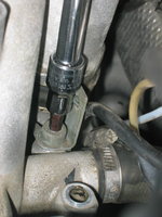
Here are a couple of photos of the block drain plug, draining coolant into the pan. The late-style block drain plugs utilise a 6mm Allen fitting, and I was easily able to reach it from under the car with a one-foot 3/8" socket extension, used with a "wobbly" attachment adjacent to the 6mm Allen socket. After cracking the plug loose, I barely snugged it back up, and attached a 12-inch length of 1/2" inside diameter hose, to use as a drain. After pushing the drain hose onto the drain plug, I just turned the hose a couple of times to re-loosen the plug in the block, and the coolant started immediately draining into the pan.
IMG_8755.jpeg IMG_8756.jpeg IMG_8757.jpeg


Between draining the radiator and one side of the block, I drained a total of two gallons + a half-quart of coolant.....so a total of about 8.25 quarts, or 8 liters.

After draining everything, I turned my efforts to loosening and removing the intake manifold. The manifold is held to the cylinder head by 12 bolts of 6mm Allen size. The bolts run along the sides of the intake manifold, with the rear of the manifold being held by four bolts (two per corner).

Here, the two clamps securing the "short hose" between the water pump assembly and the intake manifold, are loosened.
IMG_8758.jpeg IMG_8759.jpeg IMG_8760.jpeg


And here, the first of the twelve 6mm Allen intake manifold bolts is removed.
IMG_8761.jpeg IMG_8762.jpeg


These intake manifold bolts often, over the years and miles, tend to collect dirt and dust in the center of the bolt, where the Allen key is inserted. Most of the 12 bolts were blocked up with dirt and sand on my car, so I used the top of a scratch awl to clean them out, as shown below. This ensures a far stronger "bite" with the Allen socket when removing them.
IMG_8764.jpeg IMG_8765.jpeg


Removing the last of the 12 bolts, at the rear of the intake manifold on the driver's side.
IMG_8766.jpeg


Next up, loosen the clamp that holds the rear heater hose to the intake manifold. Slide the loosened clamp up the hose, and work the end of the hose off of its flange on the intake manifold, as shown. Note that removing both the heater hose and the "short hose" on the front of the intake manifold did NOT result in ANY leakage of coolant anywhere. This is because I had already drained enough coolant from the engine that there was not enough to leak out of these hoses.
IMG_8767.jpeg IMG_8768.jpeg


After everything is disconnected from the intake manifold, it's time to begin removing it from the engine. I used a large flat-blade screwdriver to wedge between the top of the block and the bottom of the intake manifold. Just a little levering pressure was enough to break the manifold loose. From there, it took a bit of effort to work the short hose off of its flange on the front of the manifold, but it did come off fairly easily, as shown below.
IMG_8769.jpeg IMG_8770.jpeg IMG_8771.jpeg


From there, you can begin to lift the manifold, slowly, out of the engine compartment. It's heavy, but easily within the realm of being a one-man job. In the sequence below, you can see the manifold gradually loosening and then coming out the engine compartment.
IMG_8772.jpeg IMG_8773.jpeg IMG_8774.jpeg IMG_8775.jpeg


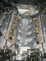
Here you see the top of the block immediately after removal of the intake manifold. Fairly dirty.
IMG_8776.jpeg IMG_8777.jpeg


And here, you see a few views of the removed intake manifold setup. I removed it with the ETA and hoses/pipes still installed, believing that it would be easier to disassemble it outside of the car. I was proven correct.
IMG_8778.jpeg IMG_8779.jpeg IMG_8780.jpeg IMG_8781.jpeg IMG_8782.jpeg


Removing the vacuum lines threaded through the inside of the intake manifold led to the "explosion" of this line (which leads from a nipple on the back inside of the intake manifold, directly through the manifold to the EZL), in to about 15 pieces.
IMG_8783.jpeg


A view of the Texas sand that was sitting on top of the union where the intake manifold met the cylinder head. You can see the dark intake manifold gasket.
IMG_8784.jpeg


A couple of views of the intake manifold gaskets, removed from the car. Note that they are the original factory units, with the MB star and part number, and were made by Elring. This confirms that I will purchase Elring replacement manifold gaskets when I order parts.
IMG_8785.jpeg IMG_8786.jpeg


A few views of the intake ports, where the air flows into the cylinders past the valves. In a couple of views, you can see pintle caps that fell off of the fuel injectors when I removed them from the intake manifold. I'll need to fish these pintle caps out of the intake, and clean up this area as well as I can.
IMG_8787.jpeg IMG_8788.jpeg IMG_8789.jpeg


A close-up view of the dirt inside the engine's "Vee," underneath the intake manifold.
IMG_8790.jpeg


Beginning disassembly of the intake manifold.
IMG_8791.jpeg IMG_8792.jpeg IMG_8793.jpeg


A downward view of the ETA. And removing the ETA return spring.
IMG_8794.jpeg IMG_8795.jpeg IMG_8796.jpeg


Removing the second ring clamp that holds the black rubber boot between the ETA and the MAF.
IMG_8797.jpeg


More disassembly.....
IMG_8798.jpeg IMG_8799.jpeg IMG_8800.jpeg IMG_8801.jpeg IMG_8802.jpeg


Removing the rubber ETA boot, piece by petrified piece....until it comes off.
IMG_8803.jpeg IMG_8804.jpeg IMG_8805.jpeg


To remove the ETA from the bottom half of the intake manifold, you have to loosen four 5mm Allen bolts that hold it down. These bolts, like the intake manifold bolts, are often full of dirt. Use an awl or a sharp nail to clean the bolt heads, for a better bite of the Allen socket/key.
IMG_8806.jpeg IMG_8807.jpeg IMG_8808.jpeg IMG_8809.jpeg


Removing the two 10mm bolts that hold the throttle cable assembly to the intake manifold...
IMG_8810.jpeg


Next, after loosening the ETA, you can move it around a little bit. Using a large pair of pliers, compress the clamp that holds the vapor hose to the ETA, and work the end of the hose off of its nipple on the ETA. The end of a flat-blade screwdriver can help begin to "persuade" the end of the hose to slide off of the nipple.
IMG_8811.jpeg IMG_8812.jpeg IMG_8813.jpeg

Remove the hose from the intake manifold assembly.
IMG_8814.jpeg


Rotate and work the ETA out of the intake manifold assembly.
IMG_8815.jpeg


Inspecting the bottom half of the intake manifold, where the ETA mounts up. Gummy and carbon-y.
IMG_8816.jpeg


Standing the intake up on end, after ETA removal, to get a better view.
IMG_8817.jpeg


A few views of the ETA after removal. You can see where my mechanic shop, when I lived in Portland, slit open the ETA cable to check on its condition. They taped most of the slit back up. Also, another view of the ETA label showing the production date, and the bottom of the ETA.
IMG_8818.jpeg IMG_8820.jpeg IMG_8821.jpeg IMG_8822.jpeg


Next, it's time to separate the halves of the intake manifold. Just four 5mm bolts hold the halves together.
IMG_8823.jpeg IMG_8825.jpeg


The halves of the intake manifold immediately after separating them.
IMG_8826.jpeg


Removing the hard metal vapor line. The lower end of this line (the dark section) can get clogged up with carbon. A close-up view of mine shows that it is about 30% clogged. Soaking it in carb cleaner will make it like new again.
IMG_8827.jpeg IMG_8828.jpeg IMG_8830.jpeg


The rubber donut rings that hold the two halves of the intake manifold together. They were not complete fossilized, but were not nearly as supple as they once were. At $6.66 apiece, I'll be spending the $55 for a new set. These rings are also used on the M117.
IMG_8831.jpeg


Last photos for the day ... removing the three sensors in the top of the intake manifold that measure coolant temperature. All three of these sensors I believe are original, and I will be replacing all of them with new ones.
IMG_8832.jpegIMG_8833.jpegIMG_8834.jpeg


I hope you found today's information helpful. Thanks so much for your continuing interest and support !!
 
Looks great, Gerry! Couple random thoughts before I forget:

When re-installing the ETA, either use new bolts which have pre-applied threadlock, or apply threadlock on the old bolts. Also, the FSM spec for the ETA bolts appears to be an error, it says 25Nm which is insane for an M6 bolt. Something around 10-12Nm max should be plenty. I assume you are aware of the trick (also mentioned in FSM) of using Hylomar Blue to stick the new ETA gasket to the ETA, making installation easier.

For the MAF rubber boot, the clamps should be oriented so the 7mm hex is pointing towards the passenger side. When 'clocked' properly, you can access the top one with a flex-shaft 7mm driver, allowing the MAF to be R&R'd in minutes. With a new soft rubber boot, the MAF slides in an out easily. Your old one was clearly fossilized.

A shop vac will pull most of the debris out of the intake ports/valves. You can tape a length of hose ~1/2" diameter to the shop vac to get further into the ports as needed.

:banana2:
 
I was able to confirm today that the parts department of my local MB dealership, Mercedes-Benz of Annapolis, is operating and fulfilling orders.

They provide no shipping costs and the same prices as MB Naperville, but do charge 6% Maryland sales tax. However, because MB Naperville is taking weeks to even PROCESS parts orders, let alone fulfill and then ship them, I will probably be ordering parts through my dealership here. Their Revolution Parts web site is Mercedes-Benz OEM Parts | Get Mercedes Parts

I am starting to compile my first parts order now, and will probably place it mid- to late-week.
 
Thanks Gerry. Is there a promo code for free shipping or do they just not charge for shipping at all? I can't believe Naperville has chosen to commit suicide rather than hire a few employees to help fill the orders.
 
They charge shipping per regular Revolution Parts system rates. They are local to me, so I just go down and pick up the parts and they don't ship them.
 
Around 45 minutes after I started, I had a visitor drop by my shop, our own @linjam. He came by to pick up a couple of items (a 500E repop emblem and a 124 ambient temp gauge) that he had bought from me a couple of months ago.
Gerry looked so happy, I think I'll drop my car and have him do mine ;-)
 
Gerry,

Why did you want to remove the intake manifold? Was it leaking? OR Just to clean it up?
 
Gerry, thanks for sharing this with us and for the quality of the write up. Exactly this "how-to" is a dream-come-true for junior DIYers.

Could you please briefly describe/illustrate your process for organizing removed parts, particularly nuts&bolts. Thanks
 
Gerry,

Why did you want to remove the intake manifold? Was it leaking? OR Just to clean it up?
A number of reasons:

1) The ETA was original. Living on borrowed time. Possible to remove without taking out manifold, but also stupid not to repair while the car is down for the other work.

2) Carbon buildup. I had suspected some carbon buildup in the intake system, up to and including the vapor tube being clogged. Turns out it is only 30% clogged, but I needed to know so I could clean it out.

3) Soft stuff under the hood. Vacuum lines, connectors, rubber hoses, injector o-rings, hood pad, and lots of soft parts under the hood are now 25+ years old, not to mention with 140K+ miles on them. I'm finding everything is pretty (though not 100%) fossilized. Time for a refresh to get everything operating in tip-top condition again.

4) EGR and air-injection system codes. Had these two codes, persistent, for several years. Needed to get to the bottom of why, and that meant diagnosing the systems. Disassembly and inspection is the way to do this.

5) Other work "in the area." I needed to remove the valve covers to replace them with the red ones I had powder-coated a couple of years ago, as well as to fix a minor valve cover gasket oil leak. Needed to clean up the engine anyway, particularly the front of it where the front crank seal has leaked all over.

6) Other jobs -- front crank seal, thermostat replacement, inspection of chain and rails, lower wiring harness replacement, replacement of heater hoses, and so on. Lots of preventative maintenance and jobs that needed to be done because of small issues. Nothing by itself a show-stopper, but needed maintenance. Remember, ALL cars with 100K+ miles have $10K of deferred maintenance. My car is rapidly proving that out. If you think this rule is a bunch of crap.....it's not. If you own the car long enough, you're gonna pay it up ... sooner or later.

7) Inspecting previous work I'd done, such as the tandem pump rebuild, cam solenoid sealing, and so forth.

8) Curiosity. Never torn down the top end of an M119 before. Done the M117. Done the M104. To be honest other than the four-valve cylinder heads and injection system, the M119 is coming in very similar to the M117 overall.

Probably a few more reasons I'll think of later, but it's 6:30 in the morning and this is what came into my brain.
 
Gerry,

Why did you want to remove the intake manifold? Was it leaking? OR Just to clean it up?


Hang on a minute - are you suggesting there should be sound reasoning and justification for taking things apart?? :scratchchin:


20191223_163355.jpg

20191223_213254.jpg

20200104_151508.jpg

:woot:

For anyone curious the parts were cleaned by a machine shops ultrasonic bath (best 20 quid you'll ever spend!!) Then all Vapour blasting was used on all aluminium parts. Yellow Zinc plating used to restore original bolts / brackets etc.
 
I'm not going to go that crazy with plating and such, because I plan to DRIVE the car for the next 20+ years :stickpoke:

That said, the intake manifold halves are definitely getting hot-tanked soon, and I'll be replacing many of the parts that you have in your photo as well. Particularly all of the soft-parts.

Yes that's fair enough Gerry - chances are in your climate the parts will clean up well.

This motor of mine looked like a boat anchor so absolutely needed it!!

20190524_204045.jpg
 
A number of reasons:

1) The ETA was original. Living on borrowed time. Possible to remove without taking out manifold, but also stupid not to repair while the car is down for the other work.

2) Carbon buildup. I had suspected some carbon buildup in the intake system, up to and including the vapor tube being clogged. Turns out it is only 30% clogged, but I needed to know so I could clean it out.

3) Soft stuff under the hood. Vacuum lines, connectors, rubber hoses, injector o-rings, hood pad, and lots of soft parts under the hood are now 25+ years old, not to mention with 140K+ miles on them. I'm finding everything is pretty (though not 100%) fossilized. Time for a refresh to get everything operating in tip-top condition again.

4) EGR and air-injection system codes. Had these two codes, persistent, for several years. Needed to get to the bottom of why, and that meant diagnosing the systems. Disassembly and inspection is the way to do this.

5) Other work "in the area." I needed to remove the valve covers to replace them with the red ones I had powder-coated a couple of years ago, as well as to fix a minor valve cover gasket oil leak. Needed to clean up the engine anyway, particularly the front of it where the front crank seal has leaked all over.

6) Other jobs -- front crank seal, thermostat replacement, inspection of chain and rails, lower wiring harness replacement, replacement of heater hoses, and so on. Lots of preventative maintenance and jobs that needed to be done because of small issues. Nothing by itself a show-stopper, but needed maintenance. Remember, ALL cars with 100K+ miles have $10K of deferred maintenance. My car is rapidly proving that out. If you think this rule is a bunch of crap.....it's not. If you own the car long enough, you're gonna pay it up ... sooner or later.
re
7) Inspecting previous work I'd done, such as the tandem pump rebuild, cam solenoid sealing, and so forth.

8) Curiosity. Never torn down the top end of an M119 before. Done the M117. Done the M104. To be honest other than the four-valve cylinder heads and injection system, the M119 is coming in very similar to the M117 overall.

Probably a few more reasons I'll think of later, but it's 6:30 in the morning and this is what came into my brain.

Gerry, thanks for the answer and I understand fixing all that you can as a preempted strike. I am following all of your How To with much interest.

Me, I already have everything for the top end rubber replacement including the metal oiler tubes and valve cover gaskets and upper chain rails but I had no intention of removing the intake manifold and do not want to. For me, If it's not broke don't fix it. I have seen Matt remove the throttle body off of an M119 from the top. For me that's what I would do or have Matt do that anyway.

I do have other stuff to do like the fan clutch and the upper harness which I also have along with a new belt. I also plan to reseal the cam covers like JC220 did. I'm sure I will run into other stuff as I get into it.

lol
 
@a777fan (Triple Trouble) did a very similar re-do of his top end on his E420 a couple of years ago. He documented it in his owner thread quite well. I think he found much of the same type of stuff that I did - not just dirt and grime, but fossilized rubber and vacuum lines and such.
 
There is this great PDF too

 
After some discussion, and research, I've decided not to pursue re-sealing of my two cam solenoids, and just to purchase new examples of the updated version along with the updated armatures. New solenoids are $80 each, plus around $7.50 each for the armatures.

I will keep my old ones, and will pursue a re-seal of both of them to keep them as spares for my M104 (G320) if needed (which is probably likely).

I sent my ETA in to Don Roden today, for refurbishment. Nothing was blatantly wrong with it, but since it was out of the car ... and original to the car .... seemed the right thing to do to get it redone.

One thing I also didn't mention, that I'll be doing as a part of this overall job -- installation of a new factory lower wiring harness. I happened to notice it when removing and folding the upper harness back over the CAN box, and pressing on its' wiring sheath, it gave a nice hard "CRUNCH!" sound. This is probably the insulation on the wiring giving way inside the sheath. So on the new one I've been hoarding, will go....
 
I spent about an hour in the shop last night, generally beginning the clean-up of the engine.

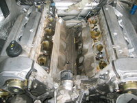
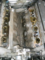
The shots below show the "before" and "after" of the cleaning of the center area of the engine's Vee, under the intake stack. I have not yet started to clean up the area where the intake manifold gaskets contact the sides of the cylinder heads.

I also cleaned and soaked the intake EGR tube in a solvent solution, and was able to remove all of the carbon deposits on it. I let it soak overnight so that the INTERIOR of the tube would get as clean as possible, but this type of cleaning will be the order of the day for things as they go back onto the engine.

Since my E500 is a DRIVER car, not a SHOW car, I won't be getting things cad-plated, but rather just cleaning things so they look nice enough, and are 100% functional.

Now, for the photos of tonight's work.

First of all, a few views of the EGR tube on the lower intake manifold, before it went into the cleaning tank. Pretty well caked-on carbon.
IMG_8835.jpeg IMG_8836.jpeg IMG_8837.jpeg


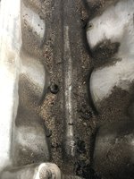
Next, a couple views of the dirt and junk on the bottom of the engine's Vee area. In the deepest places, that sand and dirt was about 1/3 to 1/2" thick where it had settled. It was less on the more raised-up areas of the engine block casting. Still -- a lot of material to get out of there !!
60780706456__317EA934-C097-4847-A2C6-33B5AAFFC6AF.JPG 60780703353__F543BAC4-95EE-4C1B-9BEB-A1E7DB3221C7.JPG


After an initial scrub with a brass brush, to loosen the crud, I sucked out as much as I could with a shop vac. Then I soaked the area in solvent for around 20 minutes to complete the loosening process.
IMG_8838.jpeg IMG_8839.jpeg


After a first-round of cleaning, here's what it looked like. Much more work to be done on the intake manifold gasket area, as well as the intake valve area (to get dust and dirt out) and a second round of block cleanup. Then the intake valve area will be taped off so that no more dirt and crap gets in there during the rest of the process.
IMG_8840.jpeg


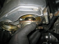
I also began removing the cam solenoids from the front of the cylinder heads. You can see the oil leaks and such. On the driver's side, you cannot remove the cam solenoid unless you remove the power steering pump reservoir to make room for it, so I will need to evacuate the reservoir and remove it. Honestly, a good opportunity to just change out the "short hose" with a fresh, new length of hose that I had left over from the previous replacement I did some years back.

A few views of the cam solenoid removal on the passenger side.
IMG_8841.jpeg IMG_8842.jpeg IMG_8843.jpeg IMG_8852.jpeg


For old-time's / flashback sake, here are some before and after views of my M117 block, from 10 years ago. This was after 183,000 miles (as compared to the 147K on my E500). Note the similarity in the castings and how things are laid out between the M117 and M119.
24123_382056313571_821723571_5113207_412081_n.jpeg 26797_431588853571_821723571_5386163_4855427_n.jpeg 23626_435142423571_821723571_5481251_2528847_n.jpeg
 
Last edited:
I have several that I use, but for quick soak type jobs like this, the Simple Green Extreme Motorsports cleaner works a treat. This [Motorsports] Simple Green formulation is fine to use on aluminum and other types of finished parts, unlike the "regular" Simple Green -- which is corrosive to aluminum and should not be used.

You can put something in a pan and soak it for 15-30 minutes, and it will come out very nice. You can get it at Amazon or Home Depot, etc.

Brake cleaner works for surface cleaning jobs (though I have not really used any yet). Brake cleaner is good because it evaporates fast, which is helpful in some situations (although using it in California, you are violating laws against air pollution).

If you have some really gnarly caked on carbon or other nastiness, Easy Off Oven Cleaner also works. But I'd only use it as a last resort.
 
I am not going to get everything nearly that clean -- just clean enough so that it looks good and is fully functional again. I prefer to drive my cars, not turn them into garage baubles, and it is highly unfortunate that the act of driving cars tends to get them dirty. By the time this car needs this type of disassembly again, I'll probably no longer be on this earth, and long past my driving days.

Every beat of my heart is one beat closer to my death. Yet hopefully the car outlives me. One can hope, anyway.
 
Simple Green Extreme Motorsports

Amazon only has "simple green aircraft extreme". Description on the bottle says it's non-corrosive. Could be the same thing as "Motorsport" and have identical performance?

Screenshot_20200408-190204.png
 
Tonight I spent about an hour and 20 minutes total in the shop. Basically removing and cleaning the power steering reservoir, and removing the second cam solenoid. I worked a little more on cleaning the engine, specifically where the intake manifold attaches to the cylinder heads.

The biggest thing I am worried about is getting the intake valves and that area clean. There is a lot of sand and debris in there that needs to be removed and CANNOT be sucked into the engine upon startup. I tried rigging up my shop vac with a small tube, but this only was partially successful. I think my best bet to remove most of the sand and debris is going to be to soak the ends of Q-tips in motor oil and swab out the intake valves. This will get most of the sand to stick to the Q-tips for removal. I'll work the vacuum more, as well. Between various methods, I'll get it done.

I didn't face this issue with my M117 or M104, because I removed the heads and they were cleaned by the machine shop.

The first thing I found tonight, was very likely the reason for the "Air Injection Inoperative" Check-Engine light (Diagnostic Module, Code 4) -- a vacuum connector had come off of the valve down by the smog pump, under the distributor. I never would have seen this disconnected vacuum line without removing the distributor cap. Here is a view of it, as I found it. When I replace the vacuum line and connector, I'll ensure that there is enough length/slack to keep things well connected.

IMG_8853.jpeg IMG_8870.jpeg


Here's a view of the cam solenoid, and as you can see the power steering fluid reservoir is blocking it.
IMG_8856.jpeg


To remove the power steering reservoir, uncap it, and suck out the fluid with a pump, turkey baster or other contraption. I used a small fluid transfer pump that is exactly suited for the task. I'll put new fluid in when I finish the job. Next remove the power steering filter. This Mann filter, I had last replaced in April, 2013 -- exactly 7 year ago !!
IMG_8857.jpeg IMG_8858.jpeg


Once the fluid is sucked out, and the filter removed, you can see the four female Torx bolts that hold the reservoir to its pedestal on the front of the cylinder head. Use the appropriate socket to remove these bolts.
IMG_8859.jpeg IMG_8860.jpeg IMG_8861.jpeg


Remove the two 10mm bolts that hold the fluid return line to the reservoir. A stubby 10mm box-end wrench (shown) comes in handy for removing the bottom bolt, which is a slight PITA to get at.
IMG_8862.jpeg


With the four female Torx bolts despatched straightaway, you can remove the reservoir. And from there, you can remove the cam solenoid from the head.
IMG_8863.jpeg IMG_8864.jpeg IMG_8865.jpeg


Here's what the cam solenoids look like, along with their mating surfaces
IMG_8866.jpeg IMG_8867.jpeg IMG_8868.jpeg IMG_8869.jpeg


Lastly, I began cleaning the dirt and dust from the intake manifold mounting surfaces. I used a plastic razor blade so as not to score the surface of the cylinder head. I only spent a couple of minutes on this, before heading into the house for dinner, and pretty much a wrap on the night.
IMG_8873.jpeg
 
Last edited:
Gerry I'm in kind of a race with you now as I'm doing the same kind of work but need to do the transmission reverse clutches so you'll definitely beat me. I got sand inside the intake ports also when I removed the manifold and seeing the amount of buildup in the passages almost compelled me to remove the head. Your buildup is almost nonexistent compared to mine. I made contact with M/B of Naperville today for some part numbers. He's down to two people including himself but didn't mention anything about shipping delays.

As an aside, I'm having the heads hot tanked as well as the manifold halves. My engine builder who I have to call and call and show up sometimes just to get a response/action from him, answered his phone on the second ring, called me back and had someone pick up the parts from my house. All in the same day. When asked about how work was going he said 'what work'. I'll get this back next week when normally it would be weeks before I could even call him for an update. He basically said that the little work I'm giving him is helping him to pay for his guys. These are tough times which don't have much of a sight for relief.

As for the ETA, definitely have another peek inside the cut sheathing. Mine seemed fine and wasn't giving any problems but I sent it to Victor (Restore your Mercedes) and not only were the wire insulators all cracked inside but the throttle body internals needed a little attention. So it was only a matter of time until this thing that wasn't giving me problems would be.

BTW, is it odd that I'm doing the same exact thing as you are but are reading the text and looking at the pictures with the interest as if it's something I've never done?
 
My ETA is on its way to Don Roden in Alabama, and it will be receiving entirely new wiring. So I am not worried about that. And it's why I am having it taken care of proactively, despite having three spare units in my basement. I wanted to keep my original ETA with the car.

As far as the dirt grains sitting on the intake valves, a combination of Q-Tips with brake cleaner or motor oil, and a shop vac with a drinking straw attached, will make very short work of the dirt. Extreme care has to be taken on the one cylinder's valves on each bank that are slightly open.

Lesson for others: clean off your engine (with the intake still on it) with compressed air BEFORE removing the intake manifold. Even then there will likely still be some stuff that gets into the engine.

I'm not stressed about it -- it's just an hour or two of work that I have to do to get things perfect.
 
The biggest thing I am worried about is getting the intake valves and that area clean. There is a lot of sand and debris in there that needs to be removed and CANNOT be sucked into the engine upon startup. I tried rigging up my shop vac with a small tube, but this only was partially successful. I think my best bet to remove most of the sand and debris is going to be to soak the ends of Q-tips in motor oil and swab out the intake valves. This will get most of the sand to stick to the Q-tips for removal. I'll work the vacuum more, as well. Between various methods, I'll get it done.

I did the top end work on my car two months ago and I faced the same problem. I dropped some pintle caps and washers inside the valves. During the whole process, I put some shop rags inside the valve holes to prevent dirt from going in, but with time they accumulated dust and other debris. I tried to be as careful as possible but when I removed the rags when assembling back the engine, some dirt made its way inside.

What I did to make sure all valves and cylinders (due to valves being open) were debris-free was to use a shop vac and vacuumed directly each valve hole. When everything seemed clean, I removed all spark plugs and used an endoscope camera to make sure all cylinders were clean. A pintle cap managed to make its way inside one cylinder and I was able to see it with the endoscope... not to mention all the dust and small debris that made its way inside the other cylinders. I removed it by using the vac until all cylinders were debris-free. You can find cheap endoscope cameras on Amazon for less than $20... great investment when doing this work!
 
I had I think three pintle caps that fell into the intake when I pulled out the injectors. They got sucked up readily with the first pass of the shop vac. After a first pass at full suction (with no attachment or modification), I put a 3/8" ID tube onto the end of the shop vac last night and was able to get a lot more stuff up, and ended up (just on a few valves) with even more stuff out using Q-tips soaked in solvent.

Based on the limited work I've done to fix this, I have no doubt that I can get 98% of the dust out of the intake and off of the intake valves. Big picture, as I said, I'm not worried -- it's just going to take an hour or two of careful, methodical work to get things cleaned up.
 
Today I placed a few orders into the queue, totaling around $350 between AutohausAZ, Amazon and MB Annapolis.

Ordered every soft part in the engine compartment, including all vacuum line, rubber connectors, plastic clips, zip ties, and cable sheaths. Also ordered intake manifold gaskets, EGR gasket, new MAF ring clamps, cam seals, fuel injector rebuild parts, EGR pipe gaskets, and so forth.

Remaining items to order: distributor caps, distributor rotors, distributor insulators, heater hoses, cam solenoids and cam solenoid armatures. I'll take care of all of that next month. No hurry on it as I still have a LOT of disassembly and various jobs to do.
 
My engine builder who I have to call and call and show up sometimes just to get a response/action from him, answered his phone on the second ring, called me back and had someone pick up the parts from my house. All in the same day.
I'll get this back next week when normally it would be weeks before I could even call him for an update.

Hopefully this situation will bring your engine builder closer to earth and make him a little more responsible
 
A quick update from last night -- I was out in the shop about 90 minutes total. Mainly I was focusing on cleaning the intake valves and chambers, and the gasket surface of the intake manifold. I was successful with about 30 minutes' effort at cleaning three of the four pairs of intake valves on the passenger side. I used Q-tips dipped in solvent to swab the undersides of the valves, and was successful in getting about 90% of the grains and crud off.

The fourth pair of valves (closest to the firewall) are open slightly, so I will take extra care in cleaning them. Then I'll start on the driver's side, and work through them.

Using fresh new razor blades, I was successful in cleaning off most all of the intake manifold gasket mating surface on the passenger side. There is a bit of brown staining on the surface, but zero corrosion, and everything is very smooth. Fresh razor blades really make a difference. I went through about 3 razor blades doing the one side.

After I seal the intake ports off, I'll clean things again with a razor blade, and also try to use some solvent to get the staining off (it is inconsequential for sealing the intake -- more for cosmetics. When everything is done, I'll unseal the intake ports and swab them out one more time for good measure, immediately before I put the manifold back on (well into the future from now). Probably will blow out each intake valve area with a few blasts from my air compressor, as well.

It looks like I'll have one more parts order from MB Annapolis in the future, as well as an order from FCP Euro, and one from an eBay vendor for the Beru distributor rotors. I'll make these orders likely in early May -- so in about 3 weeks.

I did last night locate the large box of rubber intake hoses and associated parts that I'd stashed in the garage. I will need to assemble all of the intake hoses, with their connectors. In addition, I located my pair of front crankshaft seals; crankshaft lock tool; chain tensioner, chain rails and plastic chain guides (which I'd replaced some years back when I installed my metal cam oiler tubes -- so they are probably in good shape); and my set of factory valve cover gaskets.

I also located the collection of smog pump hoses. It looks like I have a couple of extras of these hoses, so if anyone is interested in hoarding extra smog pump hoses, please let me know and I'll make you a deal on the extra hoses that I have. They are not expensive.

So plenty of adjunct items to do, as well as install the lower wiring harness that I've had in my parts stock since 2015.

The other task I started last night was the removal of the radiator, which I mostly got removed. This will give me a bit more room up front for the front crank seal operation, as well as the replacement (FINALLY) of the fan clutch with the brand new factory unit I've had since the 2015-2016 time frame. The lower hose connection at the bottom of the radiator for the transmission cooler line was giving me some problem (swiveling when I turned it), so I need to jack the car up so I have more room to work on it underneath, and stabilize the hose so it won't turn when I turn the 19mm banjo bolt that connects the hose to the lower transmission cooler port. Always some complication, but I'll get 'er done soon enough.

Photos to come.
 
Last edited:
Honch - be sure to review my tip on the removal of the upper bracket and plastic plug removal (tape a thin rope on the end of the harness) before you pull it down to the ground. The rope gives you the easy path back and the new harness with the same treatment comes up easy too. Hardest part is the small starter screw and reassembly of heat shields.
 
Last edited:
Honch - be sure to review my tip on the removal of the upper bracket and plastic plug removal (tape a thing rope on the end of the harness) before you pull it down to the ground. The rope gives you the easy path back and the new harness with the same treatment comes up easy too. Hardest part is the small starter screw and reassembly of heat shields.
Thanks for the tip. I will not be getting to the lower harness replace for a bit, but this is a good reminder.
 
:update:

I spoke with Don Roden just a few minutes ago. He has my ETA in his possession and we will speak on Monday after he has the time over the weekend to tear it down and test it.

Just got home from my second trip out this week -- I dropped the two halves of my M119 intake manifold off at Jackson Auto Machine in Hanover, MD, near the Baltimore Airport. He's going to tank and clean the manifold in the coming days, and he expects it to be done on Tuesday or Wednesday next week.

The first part of my parts order from AutohausAZ is arriving today (ordered just yesterday).

My first order from MB Annapolis is expected to be in by Tuesday or Wednesday of next week. All of the parts I ordered except three minor parts were in the Robbinsville, NJ warehouse. The three minor parts are coming from Germany.

Once I get the radiator out of the car, I'll be removing the fan clutch and accessories on the front of the engine, and will probably get started on the front crankshaft seal replacement over the weekend.
 
Back
Top