• Hi Guest !

    Welcome to the 500Eboard forum.

    Since its founding in late 2008, 500Eboard has become the leading resource on the Internet for all things related to the Mercedes-Benz 500E and E500. In recent years, we have also expanded to include the 400E and E420 models, which are directly related to the 500E/E500.

    We invite you to browse and take advantage of the information and resources here on the site. If you find helpful information, please register for full membership, and you'll find even more resources available. Feel free to ask questions, and make liberal use of the "Search" function to find answers.

    We hope you will become an active contributor to the community!

    Sincerely,
    500Eboard Management

HOW-TO: M104 / W124 Top-End Rebuild [Cylinder Head / Gasket]

One item, that I want to underscore for all future readers (and potential users) of this thread. This is a VERY important step that should ALWAYS be followed.

When re-installing the timing chain tensioner, per the factory procedure, one MUST take the step of disassembling the tensioner to "reset" it before bolting it back on to the engine.

One individual who used this HOW-TO to guide their engine re-assembly did not take this step, and ended up snapping the sprocket off of one of their cams due to directly re-installing the timing chain tensioner.

The tensioner's design is such that it "sets" itself at a certain point via an irreversible, internal self-ratcheting mechanism. This ratchet must be "reset" through disassembly of the tensioner (a 5-minute job) before re-installing the tensioner onto the engine.

If one buys a new tensioner, then one should make sure it's set correctly (i.e. not ratcheted) before installing it.
 
Gerry, Thank you for taking the time to document this rebuild, It was very helpful. I just fired up mine last night. I was half shocked that the car didn't ex/im plode
 
Gerry, Thank you for taking the time to document this rebuild, It was very helpful. I just fired up mine last night. I was half shocked that the car didn't ex/im plode
Great - and glad the documentation was helpful. As long as the engine turns without interference, and you disassemble & then re-assemble (or better yet, REPLACE with a factory piece) the timing chain tensioner, you should be good to go.

Check for oil leaks at the valve cover and adjust bolt tension on the cover bolts as needed.

It always thrills me when folks are successful with jobs based on the HOW-TO articles on this site.

It's amazing that this HOW-TO has received more than 28,000 views, to date. There must be a huge interest/demand for M104 top-end work.

Congratulations !!!

Cheers,
Gerry
 
You should be in a perpetual state of "thrilled" Honch, I get PM from noobs from several sites who have read these How To threads of yours and others and just get it so much clearer than the manuals. So while not always known to you, others have thrown out their Kent subscriptions and Chilton's manuals in favor of the HHT (Honch How To) series! I for one have retained separate PDF of every one posted.
 
I think 400Eric's drag-racing thread is also up there, as well. Haven't looked lately at the view-total for it, though.

Indeed, it has over 42000 views!
A quick perusal shows the M119 vs M113 thread and Russian EPC thread both at 26xxx.
 
I am sure that the vast majority of those 42K views are Eric checking the thread constantly to see whether someone has replied to it :tumble:


:whistling2:
 
Indeed, it has over 42000 views!
A quick perusal shows the M119 vs M113 thread and Russian EPC thread both at 26xxx.
Is there a link which shows the top viewed threads, or do you have to poke around and look for high numbers?

:matrix:
 
Is there a link which shows the top viewed threads, or do you have to poke around and look for high numbers?

:matrix:

If there's an easy way I don't know about it. I just went thru the forums and ordered the view list.
 
Hello,

In addition to re-setting the timing chain tensioner before installation, ( which is actually a well understood fact, & why one should pay for the expertise of a qualified mechanic ), if there is any doubt as to its operation, eg, sticking or binding, it should be replaced with a brand new OEM tensioner, no questions asked, & no chances taken. You also rotate the engine over by hand to re-insect timing mark alignment, & check that the ratchet-mechanism of the tensioner is working. You can check this to by rotating the engine the opposite way, as this reveals the actual amount of slack in the chain. Any doubts, reveals possible problems.

It seems Mercedes Benz Spare parts will also be happy with this thread !

Regards,

Sellc
 
You can check this to by rotating the engine the opposite way, as this reveals the actual amount of slack in the chain.
It is my understanding that the engine should NEVER be rotated in the opposite direction from which it rotates while in operation.
 
Hello,

There's nothing wrong with rotating the engine by hand the opposite direction at the crankshaft a few degrees to see whether the tensioner ratchet mechanism has released / extended itself, or whether it's remained stuck from the re-setting. Ideally, & afterwards, with the timing marks found to be satisfactory, & the chain has most of its slack taken-out, you then with the spark-plugs removed crank the engine until you have oil-pressure reading on the gauge, & then visually note its flow on the over-head gear. This will also allow you to confirm that the chain is at the correct tension, & that the tensioner is working as it should be, since the oil pressure will have activated the internal components of the tensioner & applied hydraulic oil-pressure via the plunger onto the chain. You can then with a long screw-driver confirm the plunger is locating, as it may move back a little, before locating itself on its ratchet. Cranking also lubes all of those dry bearing shells inside the motor that have not seen any oil in a long while. This assures longevity of your motor, & assures no rattles on first start-up.

Regards,

Sellc
 
Last edited:
:doh: So THAT'S who got in line before me. Excellent. Good for you, Ken!
 
hi all, i have a m104.992 in a e320 coupe and i am trying to locate the MAP switch in engine bay. any help would be apreciated. thanks
 
I'm guessing "manifold air/atmospheric pressure"...?

On the M119 LH cars this function is performed by the EZL, on M119 ME cars there is a separate sensor above the water pump. I'm not sure how the M104 HFM works.

:scratchchin:
 
Not sure what you mean by "MAP switch"? What does it control?

I mean manifold absolute pressure sensor, i called it switch because you do so in your 2nd post, pic 23.

Im in hunt of dtc error, i get 23 blinks on pin 8. and i am very confused now, what exactly is this error :

"23 Intake manifold pressure (in base module pressure sensor-) with engine running too high/low"
(i think this is for california version, with integrated diagnostic module)

or

"23 Ignition output 2 or ignition coil for cylinder 3 and 4 (Engine 111, cylinder 2 and 3)"

This is e320 '94 coupe euro, m104.992, coils and Ht leads have 10k km, both beru.

is it the coil error or manifold pressure? [emoji26]


Sent from my iPhone using Tapatalk
 
i've swapped 1&6 cyl coil with 3&4 cyl coil, still same error 23, harness date is 2001 [emoji848]


Sent from my iPhone using Tapatalk
 
Can the "smear" that is used to adhere the ETA-to-manifold gasket to the ETA be purchased at a local parts store?
Yep. Plain blue Hylomar HPF, nothing fancy... might need to Google and find out what the name of the stuff is at the local McParts, as it may or may not say "Hylomar" on it. Try NAPA...

:mushroom:
 
Ok. I was wondering if the maple syrup colored goo I normally see on the bottoms of ETA's was something special...
Yep. Plain blue Hylomar HPF, nothing fancy... might need to Google and find out what the name of the stuff is at the local McParts, as it may or may not say "Hylomar" on it. Try NAPA...

:mushroom:
 
Factory goo may have been different, or a previous mechanic may have used something different. A thin coat of blue Hylomar works well, all it does is hold the gasket in place during installation.

:strawberry:
 
This discussion was intriguing me, as I didn't remember when I did the M104 top-end refirb, that any "goo" was required for the gasket between the bottom of the ETA and the manifold.

It's a gravity fit, and the ETA fits straight downward onto the top of the manifold. So why would "goo" be required to hold it in place?

I also don't recall that any "goo" was specified in the factory service procedure for R&R of the ETA from the manifold. There's four bolts that hold the ETA (through the holes in the square gasket) to the top-facing mounting surface of the intake manifold.

Same thing for the small gasket that is between the intake manifold and the end of the EGR tube where it bolts on .... no "goo" required.

Removal:
proxy.php
proxy.php


Installation:

proxy.php
proxy.php
proxy.php
proxy.php
proxy.php
 
It's more of an M119 thang. I agree, Gerry, with the manifold off it should be goo-free on the M104.

:jelmerian:
 
It's more of an M119 thang. I agree, Gerry, with the manifold off it should be goo-free on the M104.
Even with the intake manifold ON the head it's a goo-free thing with the M104. The ETA is pretty easy to access on the 104, a fair bit easier than on the 119, where its location is about deep as the Marianas Trench.

So the next question would be that if this was an M119-related question, why is it in an M104-specific thread on the forum?

:mushroom:
:scratchchin:
:detective:
 
It may have been an M104 question... can't keep up with Stevester's fleet!!

:burnout:
 
Re: M104 / W124 Top-End Rebuild

Gerry, great write up.
I read the section where you took inventory of the vacuum lines.
I did not see which lines connect to the circled in red nipple on the lower intake.
I am having idle issues on my M104. In search of the culprit, I saw that there was not a vacuum line connected to the nipple circled in red. The only thin on the nipple was a mushy deteriorated rubber line.
Which vacuum line connects to that nipple?
Thanks in advanced.

Correction: I have inserted the correct photo.
I think I know what my answer is. My 1993 M104 might have a 1992 lower intake, straight from the factory. And perhaps that 1992 lower intake had a use for the nipple. But I think on 1993's the nipple is just capped with a rubbed cap.
The area in question is now correctly in red. And on Gerry's the nipple is not there. I checked my 95' e320 and it looks just like this pic, it's also void of a nipple. You can see were the casting has been modified to eliminate this nipple.
 

Attachments

  • Gerry's Lower Intake M104 mark up 2.jpg
    Gerry's Lower Intake M104 mark up 2.jpg
    692.5 KB · Views: 27
Last edited:
Gerry - I was told the valve-cover is magnesium (at least for the C36) and that it must be Dow 7 or Dow 9 primed PRIOR to painting or powder-coating otherwise it will out-gas and start bubbling/showing.

Regardless, I will call Precision Powder coating in Spring. TX.

Thanks,
:-) neil
 
Last edited:
The covers on the 104s are definitely magnesium - that was confirmed by the powder coaters. Two cars I know of have covers painted by the shop in Spring -- 281lxm's spruce mafia E500 and maui's option-loaded E320 white wagon.

Cheers from Victoria Pub, across from Hyde Park, central London
 
This thread is gonna pay dividends when I have to re-do the top-end of my M104 in my G-wagen......I'll get to relive the adventure all over again. The G-wagen just turned 120K miles.
 
Started my own head gasket replacement project two days ago. I read this How-To by Gerry back and forth, I felt like I have done the job. Of course, there are always some complications beyond what have been covered by these excellent records. I also consulted the post from Pelican parts and videos from youtube to answer a few questions I had. The procedues outlined by Pelican parts are very systematic and easy to follow if you only do head gasket. Gerry's is for the complete top-end rebuild.

My approach is a zone like approach. In Day 1, I removed everything on the top and the front, including the harness, hoses, spark plug cover, cross-over tube, etc. Then, I started to address the drive and passenger side of the engine.

I bought a set of 12 food containers and labelled them. All bolts, nuts, and little items get inside these containers and then sealed.

Day 2, I spent 1.5 hours and started working on the exhaust. I think, based Gerry's post, that the four bolts connecting manifolds to the exhaust tubes must be removed from the bottom. After that, I see clear path to the rest of the job until head bolts and the head lifting without a hoist.

Day 3, ....

Other than clear pictures and detailed descriptions, the part list provided by Gerry is invaluable. I don't go out and replace them all, but with all the part numbers, I sure can order correct parts.

Thank you again for such excellent post.

jftu105
 
Last edited:
Day 3, made some good progress to remove the fuel rail, intake manifolds, and one of the exhaust manifolds. The exhaust manifolds nuts and studs were coming out as one piece, except two of them. One of them is the front lower one which prevents the manifolds to be slided out easily. I had to really pry it hard to get it out. Stopped half way through the 2nd exhaust mainfolds. Need to work from under to release the three lower nuts/studs with a 12 mm box end wrench and a PVC pipe for extension. I also removed the air pump entirely to get more room. I am getting closer to the head gasket. Will explore some DIY methods to measurement the flatness of both the head and the block. Both can warp and machining only the head does not make sense to me.

jftu105
 
I think it would be highly unusual if the block were to be warped. Even the head to be warped -- the engine would have had to be overheated in the past. If not overheated, then it should not require correction.

My E320 wagon that I did this job on, had never been overheated. The machine shop measured things at the head, and saw no warping whatsoever. They did "skim" the sealing surface of the head, but that is a standard surface preparation process and takes off only a very very small amount of aluminum to promote an absolutely flat surface for optimal head gasket sealing. Most shops will do this "skimming" on heads. They also did it for my M117 cylinder heads when I did the top end of that engine.

BTW, the M104 is an iron block, with an aluminum cylinder head mounted on top. I think it's very very difficult to warp an iron block casting. Just saying.

Lastly, the cylinder head for the M104, though heavy, is not something that requires a lift/crane to remove. I am not a physically large guy (5'11", ~200 lbs) and of average build and physical strength. I had no problem removing the head from the vehicle myself. What I did was to place several thicknesses of moving blanket on the side of the engine compartment, where the air filter assembly is located. When I lifted the head off of the block, standing above the engine, I moved the head onto the moving blankets. Then I got down from my standing position in the engine compartment, and lifted the head onto a waiting pad on the garage floor. I'd say it weighs (with cams and everything) about 125+ pounds. For two people, it would be a breeze.

Cheers,
Gerry
 
It would be great that the block is not warped and cast iron does have better dimensional stability than aluminum. However, I am going to check both. Just purchased a straight edge with 0.001" straightness error. Talked to a guy who used to run a race car engine shop on benzworld. He stated that the block does warp but he was dealing with race cars.

Have not worked on the project for three days.

Thanks again for the nice How-To. Also read your caution regarding the belt tensioner. Will be very careful when re-attaching it back.

jftu105
 
We had another forum member a few years ago, who followed this HOW-TO in redoing his E320 top end, and he removed/re-used, but didn't reset the timing chain tensioner and actually ended up snapping off the cam sprocket, I believe. This is a very very imperative step and it only takes a couple of minutes. If not done, results can be catastrophic.

Cheers,
Gerry
 
Gerry,

Made some progress today. Got all the manifolds off. The nut basically fused to the stud and the lower three inside were a pain to remove. Also opened up the valve cover and practiced on the timing setting. I found that for my engine, to get those two 4 mm pin to set exactly, the timing marking is not right at the line between T and 0, but on the 0 exactly. I also read about some people got it at the line between 0 and 0. We are talking about 1 degree difference on the crankshaft, but is it correct with the camshaft. I am going to mark it before I loosen the timing chain. Next, get the timing chain cover off.

Thanks for the reminder on the chain tensioner. I will make sure that I follow your instruction closely.

jftu105
 

Attachments

  • IMG_2819.JPG
    IMG_2819.JPG
    824.1 KB · Views: 28
  • IMG_2818.JPG
    IMG_2818.JPG
    758.4 KB · Views: 29
  • IMG_2816.JPG
    IMG_2816.JPG
    641.4 KB · Views: 32
It looks to me like that is closer to 3-4 degrees off, not just 1 degree. This is about the same as I had at same point in disassembly.

The critical thing is in the re-assembly, not the dis-assembly. In the disassembly, it really doesn't matter as you're taking things apart. Mainly, it's just an indicator of chain stretch. Depending on the mileage on the engine, that is also a direct indicator of the frequency and quality of oil changes. Your engine does look pretty clean on the inside, so that's a big visual positive.

The timing chain tensioner install/reset procedure is detailed in the factory service manual, page attached to this post. For my top-end rebuild, I installed a new tensioner, as shown in the photos.

Re-using old or installing new tensioner, you still MUST install it per factory procedure.

Cheers,
Gerry
 

Attachments

Gerry,

Thanks a lot for the tensioner document. I did some study on it to learn about the "reset". Basically, the thrust pin with the retaining ring (a small wire ring) can only go one way, forward. The "reset" means that the thrust pin will start from beginning and when it is push in, against the chain, it will push the chain at a pressure set by the spring and the slackness of the chain and hold its position through the "rachet" action achieved by the groove and the retaining ring. Once set, it will not go back. If the chain becomes more loose, the spring will push it forward to maintain the tension. Without this "reset", thus removing the whole tensioner unit and then install it again without disassembly, the thrust pin could be in a position too much forward. Because it cannot go backward, the tension could be too high that chocks the chain and the sprocket to cause failure, in particular if a shorter chain is installed.

After removing the trust pin off the tensioner housing, the little retaining ring could be enlarged. As a result, the trust pin will not move forward, blocked by the ring. When this happens, one can remove the ring and clamp it tighter and put it back. Then try to put the thrust pin in and push it forward. Once it moves forward and clicks into a position, one can try to push it backward. It should hold its position without moving back. In fact, I hammered it a little and it won't go back at all. One can push it forward again to remove it for the actual installation.

This is such a clever design, but also risky unless the extreme caution is rendered to the installer. You did a great job to emphasize it. I could have overlooked it.

Thanks again.

Jay
 
The stahlwille xzn M12 socket I bought off eBay is too short to reach the head bolt. A perfect waste of $20. I had to order a longer stahlwille tool off Amazon for $42 today. It would be here next Tuesday. I guess that I have to wait until then to remove head bolts.

Stahlwille 2054X-M12 Steel Special Length XZN Screwdriver Socket, 1/2" Drive, M12 XZN Screwdriver Size, 110mm Length, 22.7mm Width

I don't want to buy a cheap tool locally, such as from autozone, for the fear that I might ruin the heat bolt. I got new ones but I am afraid to round one of them and then I would be in deep trouble.

Jay
 
:hugs:
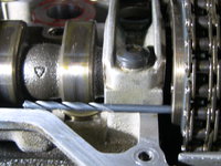
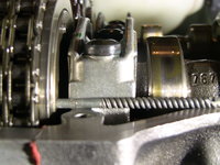
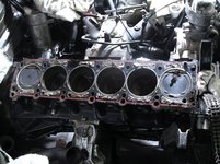
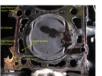
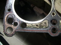
Finally received the right xzn M12 tool to loosen the head bolts. They were very tight. I took many steps, following the reverse order, to loosen them. Here are the pictures. I think I know why oil got into coolant very clearly now. Also how coolant got into the combustion chamber.

Now, the hard job of cleaning and measuring will start.

jftu105
 

Attachments

  • sad head.jpg
    sad head.jpg
    747.9 KB · Views: 31
  • sad block.jpg
    sad block.jpg
    1.2 MB · Views: 35
  • cylinder 1 no oil to coolant.jpg
    cylinder 1 no oil to coolant.jpg
    1.2 MB · Views: 34
  • Oil to coolant passage.jpg
    Oil to coolant passage.jpg
    1.3 MB · Views: 36
By examing more closely the head gasket and the cylinder head, now I have a full picture what happened to my sorry engine, which has suffered an oil in coolant problem for nearly five years. Last year, the coolant was drawn into the combustion chamber and exhaust was pressured into the coolant to have all kinds of complications. I used a bottle of Preston head gasket repair to temporily extened its life until now. The repair of this gasket stuff was almost instant and lasted for a few thousand miles, but the exhaust still gets into the coolant, to give the reservoir a high pressure even days after driving. Here are the pictures to explain the whole story. In picture 3, the gasket metal shield at cylinder #6 swelled. This was the reason for the oil in coolant in the beginning. In picture #2, the edge between the water pocket and the cylinder wall at cylinder #2 corroded and the coolant was drawn into the combustion chamber. The valves in this cylinder is a lot dirtier than the rest. In picture #1, you see how the kevlar fiber (the yellow stuff) was pushed into the corroded spot to block the passage. This happened only in less than one minute. As soon as I pore the stuff in, the shuddering of the engine stopped when this passage was blocked. Of course, this was only a temporary fix but it bought me some time. Even though the coolant won't be drawn into due to the kevlar fiber, the combustion gas pressure is a lot higher; therefore, the exhaust gas still got into the coolant to cause all kinds of leaks.

I guess that I need to go to our local yard to pull the cylinder head off a 1995 E320. Need to gather all the tools for this job when the weather gets better.
 

Attachments

  • gasket failure at #6.JPG
    gasket failure at #6.JPG
    811.2 KB · Views: 25
  • Corrsion at cylnder 2 on the cylinder head.JPG
    Corrsion at cylnder 2 on the cylinder head.JPG
    980.8 KB · Views: 27
  • Coolant into combustion at cylinder #2JPG.JPG
    Coolant into combustion at cylinder #2JPG.JPG
    748.6 KB · Views: 24
Take your cylinder head into a machine shop that knows MBs, and have them look at it. They can give you an honest assessment as to whether the head is salvageable or not. Often times they can be repaired/welded with good success, depending on the nature of the damage.

A failed head gasket doesn't automatically mean that the cylinder head is bad. Get a knowledgeable professional to look at it, and then make decisions from there.

Cheers,
Gerry

P.S. Please update your profile so we know generally where you are at. That will help in pinpointing resources in your area that can help you. A good machine shop should be able to tell you pretty quickly whether your cylinder head is a keeper or not. Unless it's been dramatically abused, it should be fine to re-use.
 
Back
Top