• Hi Guest !

    Welcome to the 500Eboard forum.

    Since its founding in late 2008, 500Eboard has become the leading resource on the Internet for all things related to the Mercedes-Benz 500E and E500. In recent years, we have also expanded to include the 400E and E420 models, which are directly related to the 500E/E500.

    We invite you to browse and take advantage of the information and resources here on the site. If you find helpful information, please register for full membership, and you'll find even more resources available. Feel free to ask questions, and make liberal use of the "Search" function to find answers.

    We hope you will become an active contributor to the community!

    Sincerely,
    500Eboard Management

HOW-TO: M104 / W124 Top-End Rebuild [Cylinder Head / Gasket]

Re: M104 / W124 Top-End Rebuild

Another quick update, as I'm not posting with the regularity as before:

  • All of my parts have arrived, except three of the 14 head bolts, which are coming from Germany and I should have later this week or first thing next week
  • The replacement ETA arrived today, all in good condition.
  • I am basically just waiting for the cylinder head to be returned to me, so I can begin reassembly on the top end.

Jobs currently happening (mostly already documented):

  • Finishing cleaning the sealing surface of the block and piston crowns
  • Cleaning/degreasing the timing cover and other parts
  • Replacing the "nipples" for the two hoses that attach to the bottom of the plastic portion of the intake manifold
  • Replacing the timing chain (easier with the head off, and I will document this process)
It does not look like I'll get the cylinder head back before Christmas. That is really the first thing that has to be installed before I can begin to re-assemble everything else.

Boy, it sure is easy to turn the engine when the head is off !! Very little resistance.

Cheers,
Gerry
 
Re: M104 / W124 Top-End Rebuild

:update:

Tonight is just a quick update on a couple of outstanding things:
  • Checking the stretch of the cylinder head bolts that came off the car
  • Removing the fossilized hoses from the plastic nipples on the intake manifold piece

First up .... the cylinder head bolts.
IMG_3832.JPG


I took two of the old bolts (representative sample) and one of the new bolts, and put them side by side.
Then, I measured them with my digital caliper.

  • The new bolt measured 170.8 mm long
  • The first old bolt measured 172.6 mm long
  • The second old bolt measured 171.8 mm
The factory specification for replacement of the original cylinder head bolts is if they are stretched 3mm or more. One of the old bolts was stretched 1.8 mm; the other was stretched 1 mm. Since there are only 14 of them, it seemed prudent to just purchase new ones; they are about $5 apiece. Cheap insurance.

Anyway, I thought you would be interested to know that the head bolts DO stretch and (seeing that the head has now been off the car two times) by how much.

Secondly ... the fossilized hose removal.

I think I had spoken earlier about the plastic upper half piece of the intake manifold, and the two vacuum hoses that go downward from it to the power steering pump area, and to the lower portion of the intake manifold. These two hoses fit onto a small, rectangular plastic piece with two hose nipples, that is bonded to the bottom of the upper portion of the intake manifold.

And I think you remember how I mentioned that I busted off one of the plastic nipples when I separated the two pieces of the intake manifold -- an extremely common occurrence even by trained MB mechanics working on the M104.

Well, I sourced a spare manifold at the wrecking yard, and removed the rectangular plastic piece from it, along with the ends of the hoses that I'd cut. The hose ends were still clamped to the nipples by metal MB spring clamps, as well. The task at hand was to remove the ends of these FOSSILIZED hoses from the plastic nipples, without busting off the nipples. This was not an easy task, and had to be done with care and gentleness. It took me about 45 minutes.
IMG_3833.JPG IMG_3834.JPG IMG_3835.JPG


By the way, side note .. Roma_500E, need a heated windshield washer hose, LOL? Here's a new one sitting on my workbench, along with a spare rear SLS valve (fits the E500E and 126 coupe/sedan), awaiting rebuild on my bench :agree:
IMG_3836.JPG


Now...back to the surgery done tonight...

What I did was to use a Dremel tool and a hack-saw blade to CAREFULLY cut through the metal clamps, and most of the way through the hose ends with a flat cut, stopping just short of going through the rubber and biting into the plastic nipples. I then used a very small, flat-blade screwdriver to break apart the fossilized rubber hose ends along the cuts I'd made, and this then separated and broke apart the hose ends. You can follow the progress I made below, in the photos.

I was successful and ended not even putting a single nick or scratch into the plastic nipples. I have NEVER in my life seen rubber that is so hard. It had literally NO give or flexibility left in the rubber.

This is an important operation and in the future, anyone reading this who works on an M104 would be WELL-SERVED to CUT the two hoses in half BEFORE separating the two halves of the intake manifold. The hoses are cheap -- about $8-11 each. I will use regular automotive ring clamps to re-attach them, as the MB spring clamps SUCK.
IMG_3837.JPG IMG_3838.JPG IMG_3839.JPG IMG_3840.JPG IMG_3841.JPG IMG_3843.JPG IMG_3844.JPG IMG_3845.JPG IMG_3846.JPG IMG_3849.JPG IMG_3850.JPGIMG_3847.JPG
 
Re: M104 / W124 Top-End Rebuild

No wonder the stealership charges so much for this type of work.

You may have already answered this, but is there a part number on the rectangular plastic piece?

I have to ask what are you using as a guide for this project? For someone that does not do this kind of work every day you seem to have a very good handle on it. :applause:
 
Re: M104 / W124 Top-End Rebuild

The rectangular plastic piece is NOT available as a separate piece. It is part of the plastic piece of the intake manifold, which was I think around $500-600 from parts.com when I checked a couple of weeks ago. I got the used intake manifold from the wrecking yard for $25 :D

No guide, other than specific service manual instructions for particular jobs (for example, removing the cylinder head, for when I re-install the cams, install a new timing chain, and re-time the engine to get the crank and cams back in synch. Other than that, it's just basically common sense. Just work methodically, and not in a hurry.
 
Re: M104 / W124 Top-End Rebuild

:update:

This afternoon, I spent about 3 hours in the shop doing a variety of miscellaneous tasks, as I get closer and closer to getting the cylinder head back from the machine shop. Specifically, the tasks I worked on today included:

  • Preparing and retrofitting the rectangular plastic piece onto the intake manifold
  • Continuing to clean and prepare the engine block (piston crowns and top deck) for the cylinder head fitment
  • Cleaning and chasing the threads for the 14 cylinder head bolt holes in the engine block
  • Initial cleaning of the timing chain cover (focusing on the bottom and rear sealing surfaces
Here are a few photos from today's procedures.

First of all, I had to remove the old rectangular plastic piece from the car's upper (plastic) intake manifold. And I had to do this without breaking off the raised sealing lip on the manifold. I didn't care about preserving the rectangular plastic piece itself, seeing as I had another one previously prepped and prepared to go into its place.

I used a couple of different sizes of flat-blade screwdriver to prise up the edges of the rectangular plastic piece, taking it off in chunks until I finally got the bulk of it off.
IMG_3865.JPG IMG_3866.JPG IMG_3867.JPG IMG_3868.JPG


Then I thoroughly cleaned the compartment in the intake manifold that had been previously covered up by the rectangular piece. I also reamed out the pipes on the replacement plastic piece using a screwdriver -- there was quite a build-up of carbon in this piece, particularly in the larger tube. Here are "before" and "after" shots of the compartment in the intake manifold.
IMG_3869.JPG IMG_3870.JPG


The next step was to mix up and apply a solid coating of JB Weld both to the mounting channel and to the vertical sealing surfaces of the rectangular piece. After doing this, I balanced a couple of clay bricks on top of the rectangular piece to weight it down for a few hours, while the JB Weld cured.
IMG_3871.JPG IMG_3872.JPG IMG_3873.JPG IMG_3874.JPG


Next, while the intake piece was bonding itself to the manifold, it was time to start in on the engine block. I cleaned piston crown #4 and scraped the block's sealing surface, cleaning it with a razor blade as good as I could through cylinders #4 and #5.

Then, it was time to work on the block itself. First, I used a supply of Q-Tips from my wife's make-up drawer to swab out any oil and coolant that had become trapped in the cylinder head bolt holes during the intake manifold and cylinder head removal process. Some of the holes had a good 1/2 to 3/4" of oil or liquid trapped in them, while others were fairly dry. It is IMPERATIVE that all liquids be removed from these cylinder head bolt holes so that proper torque can be achieved when the head bolts are re-inserted during cylinder head installation. But MORE IMPORTANTLY, it is important that no liquid be in the bolt holes so that the condition known as "hydro-lock" doesn't occur -- hydro-lock is when the liquid at the bottom of the bolt hole stops the cylinder head bolt from being tightened further, and the bolt strips out on the block ... causing great and time-consuming problems.

So it's an excellent precaution to first swab out any excess liquid from these 14 holes. Here is a photo of my Q-tips at the end of the job. As you can see, there was a fair amount of liquid in most of the holes.
IMG_3885.JPG


After doing this, I then ran a tap down into each hole. This removes any further dirt and crap down in the holes, and ensures that the threads are in good condition. The tap for the M104 block's cylinder head bolt holes is M12 size with a 1.75 pitch (M12x1.75) which is good information to remember.

Every two holes or so, be sure to coat the threads of the tap with a light coating of motor oil, as I show here.
IMG_3881.JPG IMG_3880.JPG


Then, carefully run the tap down into each hole. You should feel little to no resistance at first, and then only a bit more as the tap's threads mate with the block's threads and it descends down into the hole. IF YOU FEEL SIGNIFICANT RESISTANCE, AND/OR SEE METAL SHAVINGS COMING OUT OF THE HOLE, STOP IMMEDIATELY AND BACK THE TAP OUT OF THE BLOCK. You may have the wrong size or pitch of tap. Here are some views of me doing this.
IMG_3876.JPG IMG_3875.JPG IMG_3877.JPG IMG_3878.JPG


After running the tap down into the block successfully, I then re-run it one more time. Because you've cleaned/cleared the threads in the block the first time using the tap, you should be able to run the tap completely down into the block with the pressure of a single finger on the tap handle, the second time.
IMG_3879.JPG IMG_3882.JPG


When you remove the tap from each hole, take a look at it closely for shavings or metal particles, and for dirt and oil. Clean the tap off for the next hole, and as I mentioned earlier, oil it lightly every couple of holes or so.
IMG_3883.JPG


Here are things as they stand tonight ... just two more piston crowns to clean and scrape lightly, and then the rear end of the block's deck to clean. Then go over everything with a Scotch Brite pad, and a final vacuum to remove any dirt and shavings. Probably another 1.5-2 hours of work, carefully done, and then I can put the block to bed until the cylinder head arrives.
IMG_3886.JPG


The last job of the night, was to get started on cleaning the front upper timing cover. This is the cover that can leak at the bottom every 20-30,000 miles on the M103 and M104 engines. Here are a couple of views of me cleaning the cam solenoid mounting surface for the intake cam. It is only about 90% clean, so will need a bit more going over to be perfect, but it's pretty close to being ready. I used Chlorinated (non-Jerry Brown formula) Brake Cleaner on a rag to remove the residue from the factory anaerobic sealant.
IMG_3887.JPG IMG_3888.JPG


Next up was the Viton sealing ring on the inside of the cover. This sealing ring was smashed down flat, so I had to pick the edge of it up with a razor blade to get enough up so that my small pick could lift it out of its channel. I have a replacement seal waiting for the point where I reassemble and install the front cover.
IMG_3889.JPG IMG_3890.JPG IMG_3891.JPG


Then it was time to clean the very very critical lower sealing surface, which sits on top of the "u"-shaped seal and whose corners meet at the "Bermuda Triangle." It is extraordinarily important to get this sealing surface clean. Luckily, mine wasn't too dirty because no previous mechanic had slopped RTV on this surface, which it seems about 50% of them do. If this had been the case, it probably would have taken me 30-45 more minutes to clean all of the old RTV off of this surface (not to mention the block, head and lower timing front cover). Again, I'm only about 90% done and will finish the job tomorrow.
IMG_3892.JPG IMG_3893.JPG


As I packed up for the night, I removed the bricks from the rectangular piece on the intake manifold and put the manifold piece in a safe place in the garage, to cure for the night. It should be ready after tomorrow for the new rubber hoses. I will replace the MB spring clamps (which I can't stand) for traditional "radiator" style worm-gear hose clamps, which can be tightened and loosened with a screwdriver. I don't know why MB didn't use these in the first place.
IMG_3896.JPG


All in all, it was a fairly productive evening in the shop doing these fairly mundane, but very important, tasks in preparation for the re-assembly phase when the cylinder head arrives in the coming days.

Cheers,
Gerry
 
Re: M104 / W124 Top-End Rebuild

Bobby Scroggins of Scroggins Machine just called me with an update. The head looks good, no cracks or problems holding pressure, no valve guides needed any attention, the valve guide seals were replaced, and he says it cleaned up very nice. All of the cam bearing caps and bolts came off with no issues.

The head should be ready to go early next week. Which is just about perfect as I get everything cleaned up, prepared and ready to go for the re-installation of the cylinder head.

The remaining big job is to roll in a new timing chain, which will be one of the next things that I document here.

Cheers,
Gerry
 
Re: M104 / W124 Top-End Rebuild

Some photographs of the cylinder head coming back together .....
2013-12-27 13.33.53.jpg 2013-12-27 13.34.01.jpg 2013-12-27 13.34.30.jpg 2013-12-27 13.34.50.jpg


And of the now-cleaned lower half of the intake manifold....
2013-12-27 13.34.08.jpg 2013-12-27 13.34.20.jpg


Remember what it looked like before ?!?
IMG_3610.JPG


The time for re-assembly edges ever closer....
 
Re: M104 / W124 Top-End Rebuild

That is interesting about the hydro-lock. Never thought that could happen. The engine looks really clean.
 
Re: M104 / W124 Top-End Rebuild

Late this afternoon, I put about an hour and a half into continuing with some misc chores that need to be done in preparation for the re-assembly, which will officially commence with the installation of the cylinder head.

First, I needed to "ream" out and clean up the infamous EGR tube on the 104. I had considered purchasing a new tube, but at $140+ from parts.com, it didn't seem like a very good purchase and would have been the single most expensive part purchased for the rebuild. Given that the tube physically is OK, it just needed to be cleaned out.

I did this by using a scratch awl to remove the deposits inside the end of the tube, through a pushing and scraping motion to loosen them. Then I emptied the scrapings into a pile on the cement, and repeated the action until I could get no more deposits out. Then, I shot a good load of brake cleaner into the now-cleared end of the tube. After doing that, I cleaned up the exterior of the tube and its flange, and clamps, with a brake-cleaner-soaked rag. It cleaned up quite nicely.

Here are a couple of photos of the tube, just before I started cleaning it today.
IMG_3898.JPG IMG_3899.JPG

Here are some photos of the cleaning process. The mountain of deposits was about 1/2" (1.25cm) tall, and looked a bit like a brown Mount Rainier in Washington State.
IMG_3900.JPG IMG_3901.JPG IMG_3903.JPG IMG_3904.JPG


Here's what the tube looked like, after cleaning.
IMG_3905.JPG IMG_3906.JPG IMG_3907.JPG IMG_3908.jpg


Then it was time to return to the task of finalizing cleaning of the top timing cover. I did this by cleaning the sealing surfaces with a Scotch-Brite pad soaked with brake cleaner, and it worked a charm....
IMG_3909.JPG


Next up, I continued cleaning the very very vital lower sealing surface, that will rest against the block, cylinder head and lower timing cover. It is imperative that these surfaces be super clean for optimum sealing, and hopefully not having to re-do this job for at least the next 50,000 miles. I also cleaned the deposits off of the hose flange on the outside of the timing cover.
IMG_3910.JPG IMG_3911.JPG


After that, I installed a new replacement o-ring to replace the flattened one I removed, in the center of the timing cover.
IMG_3913.JPG IMG_3914.JPG


My last task was to clean the tops of pistons #5 and #6, and to clean the block area around them. I worked on this for the better part of an hour, but completed the job. All that is needed now is a final scrape with the razor blade, a final vacuum with the shop vac, a final blow of the whole top of the block and pistons with compressed air, and light oiling of the cylinder walls with an oiled, lint-free rag. I will do this right before I install the cylinder head.
IMG_3912.JPG

Cheers,
Gerry
 
Re: M104 / W124 Top-End Rebuild

I couldn't leave well enough alone tonight, so I headed back out to the garage shop to do a couple of other "housekeeping" tasks in preparation for the cylinder head re-installation and re-assembly of the top end of the motor.

The first thing I did was to service the motor oil dipstick. Initially, I cleaned off the metal outside housing tube thoroughly with a shop rag soaked in brake cleaner. This cleaned off most all of the caked-on grease and dirt from the engine compartment. It wasn't bad, but there was definitely some on there. I also replaced the o-ring that seals the dipstick tube where it goes into the block, by removing the old sealing ring and sliding a new o-ring onto the tube up to the flange where it rests against the engine block.
IMG_3915.JPG IMG_3916.JPG IMG_3918.JPG


Next, I replaced the OTHER o-ring on the engine oil dipstick. This is the often-overlooked o-ring at the top of the dipstick, in the handle. This o-ring generally is NEVER replaced, and over time and with engine heat shrinks and fossilizes, causing potential oil leaks because the dipstick handle can flop around and out of the top of the dipstick tube.

Sure enough, this o-ring was absolutely FOSSILIZED on there, so I used a razor blade and then a small pick to cut it so that I could remove it. The fossilized o-ring came off in two pieces. I slid a new one onto the dipstick and into place in its groove in the handle, and this resulted in a VERY nice, tight fit for the dipstick handle into the top of the tube. As MB intended it to be. A very quick, cheap but satisfying fix. Yes, even for you M119 guys!! I'm going to do this same thing for my dipstick handle on my E500.
IMG_3919.JPG IMG_3920.JPG IMG_3921.JPG IMG_3923.JPG IMG_3924.JPG IMG_3926.JPG IMG_3927.JPG IMG_3928.JPG


Then it was time for the next job. Specifically this was to remove the resonance valve, to replace its gasket where it seals into the plastic portion of the intake manifold. Now, before I get into this, I will give a bit of background on this so-called "resonance valve." It's a very very expensive item from MB, when I checked a couple of weeks ago this valve cost over $400 !!!

Its purpose is to change the length airflow characteristics of the intake runners at speeds, and to control the air flow at idle through the intake manifold. Specifically -- the resonance valve helps increase low-end torque at low RPMs, and then increases/optimizes intake airflow through resonance tuning at higher RPMs. This improves power characteristics and helps flatten the torque curve, working in concert with the variable valve timing mechanism on the intake cam. The resonance valve works by rotating a flapper valve along a semicircular axis inside the manifold, effectively joining or cutting off two compartments. The valve has both electrical and vacuum connections, and this is how it is controlled. The M119 does not have an equivalent valve in its intake system. This was an innovation that was introduced for the M104 specifically.

Anyway, there are four 5mm Allen bolts that hold the valve to the manifold. Two of the bolts are buried underneath rubber caps that press into the top of the valve housing. You can see some of the car's original engine cosmolene that is still coating the rubber plugs, cracking as I removed the rubber plugs from the valve. If you have the chance, it is an EXCELLENT idea to get a spare valve from a wrecking yard if you have an M104, so that you don't have to pay the exorbitant MB factory price for this valve.

The valve is in two parts, so I had to remove the top part, and then pry off the bottom part using a flat-blade screwdriver. All very carefully, of course. I did a lot of cleaning up of the area and of the manifold itself as I put things back together.
IMG_3929.JPG IMG_3930.JPG IMG_3931.jpg IMG_3932.jpg IMG_3933.jpg IMG_3934.jpg IMG_3935.jpg IMG_3936.JPG IMG_3937.jpg IMG_3938.JPG IMG_3939.jpg IMG_3941.JPG IMG_3940.JPG IMG_3942.JPG IMG_3943.jpg


After replacing the gasket, I put everything back together, and it went quite quickly.
IMG_3944.JPG IMG_3945.jpg IMG_3947.JPGIMG_3948.JPG IMG_3949.JPG IMG_3950.jpg


And ... the cleaned-up intake manifold. Now all ready to mount to its mate, and onto the cylinder head !!!
IMG_3951.JPG
 
Re: M104 / W124 Top-End Rebuild

:update:

To all -- my sincere apologies about the too-frequent updates over the past few days. You are all probably thinking I am having a bad case of diarrhea of the keyboard or something.... so apologize in advance for this.

Well, about 1.5 hours out in the shop tonight and I achieved the major remaining milestone required, before installation of the cylinder head: the replacement of the timing chain. It only took about 45 minutes for the actual replacement job and that was taking my time and great care. I was very lucky to have the special Assemnacher tool that is used to press the timing chain link together and then crimp it into place, borrowed from my friend Larry Gheorge, who owns GR Auto Care (a Mercedes/BMW repair shop) in nearby Spring, Texas. Larry is always a great source of friendly MB related banter and advice, and we loan each other tools and equipment with some regularity. GR is where G-Man recently took his 500E to have the transmission rebuilt, among other work.

Anyhoo .... I had my wife help me but unfortunately as our hands were full (literally) I was unable to get photos of the actual chain replacement. BUT, there is plenty of before and after photos and I'll fill in the chain replacement process verbally so that you get a good idea for how it went.

First off, before getting started on the chain replacement exercise, I double-checked and cleaned out the channel in the top edge of the lower timing cover, where the seal will fit for the top part of the cover. I was lucky that previous mechanics had not mucked this all up with loads of RTV sealant, so I didn't have to clean out much. Just cleaned up the oil with a rag, and some brake cleaner spray to make things purdy. You can see a bit of RTV or other sealant on the underside of the driver's side timing chain rail (which I'm not going to bother to clean up) but otherwise , no muss, no fuss with the sealing area itself. It's ready for me to struggle to get the top timing cover on when the time is right.
IMG_3953.jpg IMG_3954.JPG


The next order of business was to get the exposed top of the engine covered up, in advance of the deluge of very fine pieces of ground timing chain link and pins that would soon be spraying forth from up above, as I ground down the pins to separate the chain. I put several layers of rags down to keep things well protected -- particularly the "chain box" area where the timing chain goes down to the crank sprocket.
IMG_3955.JPG


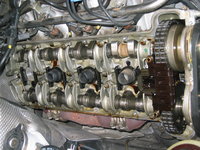
Then it was time to actually "press on" with the job of the timing chain replacement. The first step was to use my Dremel Moto-Tool, with a grinder bit attached, to grind down the pins that held the link on the chain. As I was replacing the chain with a new one, it didn't matter WHERE on the chain that I selected -- location was not important. Here you can see me as I get started with the Dremel.
IMG_3958.JPG IMG_3956.JPG


Here are some "action" shots as I ground down the ends of the pins.
IMG_3959.JPG IMG_3960.jpg


After I got things ground down, there was just a little space in between the links to work in the end of a jeweler's screwdriver, which began to pull the link cap off the end of the pin. It gave me a bit more room so that I could stick a larger, flat-blade screwdriver in there to pop it off. Here you can see the results of that. See how much the end link itself got ground down? Probably a bit more than I should have, but since it was going to be discarded, I wasn't too concerned about it .... until a few minutes later.....
IMG_3961.JPG IMG_3962.JPG IMG_3963.JPG


Here's a view of the timing chain, with the end link removed.
IMG_3965.jpg IMG_3966.JPG


Then it was time to get out the NEW Iwis timing chain, and get it ready for the forthcoming operation.
IMG_3972.JPG IMG_3967.JPG IMG_3968.JPG IMG_3969.JPG IMG_3970.JPG IMG_3971.JPG


I cleaned the metal shavings from the ground pins and end link off of the chain, as best I could with a well-oiled shop rag, making 5-6 passes to be extra sure that as much of the shavings were gone as possible. The reason being because that old chain would be descending down into the engine in just a few minutes, and I wanted to minimize metal shavings down in the chain box area.
IMG_3973.JPG


Now comes the break in the photos, so I'll have to describe the next few operations verbally, and unfortunately not illustrate them photographically.

The next step was to separate the ends of the old timing chain. I had my wife help me, and she held the two ends of the chain that appeared as I removed the end link with the attached pins, that I had ground off the other side of. She held the ends of the chain so that the chain wouldn't fall downward into the chain box, and also so that the chain would stay wrapped around the crankshaft chain sprocket.

Then I attached the ends of the new chain to the ends of the old chain, using the old and new links with pins, and end caps. I used a pair of Knipex channel-lock pliers to press the end caps onto the pins enough so that they would stay put for their journey over the crankshaft sprocket, but not tight enough so that they would be difficult to remove after the new chain was rolled into the motor.

I had my wife hold the newly combined, double-length chain up with two hands, while I rolled the old chain and part of the new chain into the engine, around the crankshaft sprocket, and out the other side. Once I rolled the link up far enough, I had her continue to hold the chain while I popped off the end links and removed the old chain.

The next step was to assemble the newly supplied Iwis master link (with pins), center link plate and end link, and join the ends of the new chain together. I used the special Assenmacher press tool to do this, after I press-fitted the end cap onto the pins, thereby relieving my wife of the need to hold the chain up further. At this point, I re-attached the bungie cord I'd been using to hold up the old chain, and she was done. Total time for her in the garage was about 20 minutes or so.
IMG_3975.jpg


Here is a photo of the old chain, just after removal from the engine after the new chain was rolled in.
IMG_3974.JPG


Here's the new end-cap, press-fitted onto the pins of the new chain's master link. The next step is to press the end-cap into place with the tool.
IMG_3976.JPG


And here's the special Assenmacher chain-press and crimping tool in use, moving the end cap into its final position on the pins. This tool costs over $800 from MB !! To operate the press, you simply turn the pin clockwise, using a 13mm wrench, to move the end cap onto the pins.
IMG_3977.jpg IMG_3979.JPG IMG_3978.JPG IMG_3980.JPG


And here's the new Iwis end cap, pressed into place on the pins. It's the darker black link in the chain.
IMG_3981.JPG IMG_3982.JPG IMG_3983.JPG


After the end cap was in place, it was time to crimp the two pins, to keep that cap in place on the chain. The beauty of the factory (and Assenmacher) chain tool is that it easily converts to a crimping tool, just by switching the "bit" in the tool by 90 degrees. So here I am, switching the tool from "press" mode to "crimper" mode.
IMG_3984.JPG IMG_3985.JPG IMG_3986.JPG IMG_3987.JPG


And here I am, using the tool to individually crimp each pin. Notice the bevel that is applied in the crimping process, to the sides of each pin. This is the same as the other pins on the Iwis chain's other links. I provide a few close-up photos for your reference.
IMG_3988.JPG IMG_3989.JPG IMG_3990.JPG IMG_3991.JPG


And, a couple of photos of the finished new chain. Mission accomplished !! The timing chain installation was a major milestone in the rehabilitation of the top end of this motor !!
IMG_3992.JPG IMG_3993.JPG

Cheers,
Gerry
 
Re: M104 / W124 Top-End Rebuild

To all -- my sincere apologies about the too-frequent updates over the past few days.

This is great stuff! Much better than reading posts about who can squeeze the biggest set of wheels on the car or the loudest, most annoying, stereo system, neither of which was intended by the original designers.

That Assenmacher tool rules! I presume the M119 chain uses the same tool?
 
Last edited:
Re: M104 / W124 Top-End Rebuild

That Assenmacher tool rules! I presume the M119 chain uses the same tool?
Yes, this tool will work with any Benz with a single- or double-row timing chain, including the M119. You can get lightly/unused chain press tools, MB OE, on eBay for $250 or so. It's not a bad tool to have, and I'm going to make the investment to get one.
 

Attachments

  • $T2eC16FHJF8E9nnC6LF+BQNQV!j4SQ~~60_57.JPG
    $T2eC16FHJF8E9nnC6LF+BQNQV!j4SQ~~60_57.JPG
    129 KB · Views: 35
  • $(KGrHqVHJCEE+Ukf6385BQNQV!Fiew~~60_57.JPG
    $(KGrHqVHJCEE+Ukf6385BQNQV!Fiew~~60_57.JPG
    495.2 KB · Views: 36
Re: M104 / W124 Top-End Rebuild

Yes, this tool will work with any Benz with a single- or double-row timing chain, including the M119. You can get lightly/unused chain press tools, MB OE, on eBay for $250 or so. It's not a bad tool to have, and I'm going to make the investment to get one.
Photos of the OE tools made by Iwis are here. A detailed procedure is at this link, shown on an OM60x diesel engine, but the procedure is the same on the double-row gasoline chains.

Note that the OE master link has a pressed-on center plate; aftermarket master links have a slip-fit center plate (both have press-fit end plates). The factory tool includes additional dies & assembly inserts to properly locate the press-fit center plate. The aftermarket tools do not have these items but they can be purchased separately from Mercedes and should work with the aftermarket/AST tool (disclaimer - I'm not positive about this). Sadly, the prices shown in the PDF above are a distant memory, some of the current prices are downright ludicrous.

:star:
 
Re: M104 / W124 Top-End Rebuild

For the M104, two different types of aftermarket chains are described in the factory service manual -- IWIS and Renold.

The IWIS chain (which is what I purchased/used) is probably the most common, and as Dave says has a slip-fit center plate. It is important to note that the center plate is THICKER than the end plate.

The AST tool that I used only comes/came with fittings for single- and double-row chains, but no additional fittings for the assembly inserts for factory chains.

This is absolutely NOT a problem, as long as one buys an IWIS or Renold replacement chain. I do not know if MB factory chains include the pressed-on center plate, or use the IWIS-style (as I show) slip-fit center plate.

Cheers,
Gerry
 

Attachments

Re: M104 / W124 Top-End Rebuild

This is absolutely NOT a problem, as long as one buys an IWIS or Renold replacement chain. I do not know if MB factory chains include the pressed-on center plate, or use the IWIS-style (as I show) slip-fit center plate.
I am not sure either. I've only done this job a few times (twice on diesel, once on M119, all many years ago) and I always used aftermarket OEM Iwis chains, as the price difference was substantial compared to OE. However, I did buy a new OE master link to get the press-fit center plate. If you don't have the OE tool with the widgets to install the press-fit center plate, it would be best to do as Gerry did on his M104, and use the master link supplied by Iwis with a slip-fit center plate.

:bbq:
 
Notes from the Machine Shop

:update:

This afternoon I picked up the cylinder head from Scroggins Machine. I wanted to get it before the New Year's holiday so that I could begin work on it soon. I expect that the cylinder head will be going back on the block this coming Friday or Saturday. The front timing cover will go back onto the car after the engine is brought back into proper time (i.e. the crankshaft and camshafts are aligned and the timing chain & new tensioner are re-installed).

From there, it should be (generally speaking) a matter of gradual re-assembly of everything. I am getting pretty motivated to get this job wrapped up and done, so I can get the car tested and back out on the road. I started this job on the evening of November 27th, so it has been exactly 1 month + 4 days that it has been "down for the count," with the last 2.5 weeks of that being more or less held up with the cylinder head in the machine shop. This took about a week longer than I had anticipated, although the Christmas holiday sort of got in the middle of that.

Anyway, here are some notes about and a brief photo examination of the cylinder head, as picked up today at the machine shop.

First off, a few "overview" photos of the cylinder head.
IMG_3994.JPG IMG_4000.JPG IMG_4007.JPG IMG_4008.JPG IMG_4009.JPG


Here's the factory proof marking in the head surface. It's now obscured because the machine shop "surfaced" the head (skimmed it with their cutter). They said that there is plenty of material on the head if and when this needs to be done again. Bobby (Scroggins) said he believes the head indeed was "virgin," meaning it had not been surfaced/skimmed in the past. So this confirms my theory that the head gasket was simply replaced on the car prior to my purchasing it, but no actual machine-shop work had been done to the head.
IMG_3995.JPG


Here are a couple of close-up views of the valves, including the factory markings on the intake valves. Notice that the intake valves are slightly larger than the exhaust valves.
IMG_3997.JPG IMG_3996.JPG


Here are a couple of views inside of the intake and exhaust ports. As you can see, they are clean and ready to go. They have not been modified or hogged out -- 100% stock for reliability and longevity.
IMG_3998.jpg IMG_4005.JPG


Here's a view of the end of the head, with a clear shot of the noses of the camshafts.
IMG_3999.JPG


A close-up shot of the exhaust cam area on the end of the cylinder head. At the center of the photo is one of the two dowel pins that will help align, and press into, the front timing cover when it is installed to cover up this area.
IMG_4001.jpg


There were two small concerns on the cylinder head -- specifically, two very small areas of corrosion. These showed up as "pitting" on the mating surface, as shown in the photos below. If these corrosion areas were worse, then they would be welded and flattened off, and thus fixed. But these were minor and didn't require additional attention at this time.
IMG_4002.JPG IMG_4004.JPG


A view of a couple of representative cam lobes. These look quite good for having 202,000 miles on them !!!
IMG_4010.JPG


The MB identifiers cast into the cylinder head exterior.
IMG_4011.JPG IMG_4012.JPG


A couple of close-up shots of the intake ports, and the rough casting adjacent to them. This is fine, it came from the factory this way.
IMG_4013.JPG IMG_4014.JPG


Here is a close-up of the combustion chamber of one of the cylinders. Notice how the threaded spark plug hole is right in the middle of the array of intake and exhaust valves.
IMG_4015.JPG

That concludes our tour of the cylinder head. Hope you found this to be educational.

Bobby Scroggins also gave me a small plastic bag of what he termed as "souvenirs." These were the 28 cam bearing cap bolts that he removed from the cylinder head, after I had stripped out a number of them and was unable to remove them.

Bobby was also unable to remove many of them by traditional means, although he did say that none of them were Loctited or otherwise chemically fastened/bonded to the cylinder head. His theory was that the bolts were just fused to the head because of their wide bolt-heads, as well as the continual hot-and-cold cycling (heating up and cooling down) of the aluminum cylinder head, which caused the fusing. They may have been over-torqued as well. He said it is not all that uncommon for this to happen. Bobby said that a bit of lubing when tightening down the new cam bearing cap bolts MAY eliminate this problem the next time they need to be removed, if they ever need to be.

Anyway, here are some photos of the couple of bolts that Bobby had to weld a nut to, in order to loosen them. That's a pretty extreme length to have to go to to remove bolts !! I put a couple of the other bolts next to them, for reference. The cam bearing caps were fastened to the head with 28 brand-new MB bolts.
IMG_4016.JPG IMG_4017.JPG IMG_4018.JPG IMG_4019.JPG


Hope y'all find this of interest.

Cheers,
Gerry
 
Re: Notes from the Machine Shop

Nothing like the look of clean heads, fresh from the machine shop.
 
Re: M104 / W124 Top-End Rebuild

Actually, if you look at the photos in post #77, the head was amazingly clean prior to the machine shop getting it. Makes me wonder if the head was hot-tanked or otherwise cleaned up at the previous head gasket replacement. It's unusual for an M119 to be this clean under the valve covers... I think only two of my ten twelve total have been this clean, with silver aluminum color everywhere. They typically have a light brown varnish on everything as seen here or here.

:wootrock:
 
Re: M104 / W124 Top-End Rebuild

Actually, if you look at the photos in post #77, the head was amazingly clean prior to the machine shop getting it. Makes me wonder if the head was hot-tanked or otherwise cleaned up at the previous head gasket replacement. It's unusual for an M119 to be this clean under the valve covers... I think only two of my ten total have been this clean, with silver aluminum color everywhere. They typically have a light brown varnish on everything as seen here or here.

:wootrock:

I don't know, Dave. My 2 M119s and M104 don't have much of any varnish. I won't get into an oil debate but I'm sure the type of oil and change interval play a vital role in keeping engine internals clean.
 
Re: M104 / W124 Top-End Rebuild

I don't know, Dave. My 2 M119s and M104 don't have much of any varnish. I won't get into an oil debate but I'm sure the type of oil and change interval play a vital role in keeping engine internals clean.
Glen, I believe you are correct. For the two motors I have that look like Gerry's M104, I think both were fed synthetic since day 1, or darn close to it. I don't have detailed enough records for the other "brown" motors (if any records at all) to determine what they had been using prior to my ownership, or how often it was changed. Very frequent dino changes could have a similar result, IIRC Gerry uses dino in that M104 but changes it every 2kmi. (!!)

Still, I think twelve different engines all between 100-200kmi is a pretty good sample size. Also, the dozen or so M119's that I've seen in P+P salvage yards all had the same brown/tan varnish... forgot to mention that. That brings the total closer to 20-25.

Oh yeah - one more data point. My new '93 also had near-silver colored cams & cam bearing caps, super clean, even with 190k (again, no records). However the cam sprockets still had a pretty thick layer of dark brown crud on them. I forgot to take before & after photos, darnit! Meanwhile, my '94 is spotless, with zero deposits on the cam sprockets. Weird.


:grouphug:
 
Re: M104 / W124 Top-End Rebuild

Actually, if you look at the photos in post #77, the head was amazingly clean prior to the machine shop getting it. Makes me wonder if the head was hot-tanked or otherwise cleaned up at the previous head gasket replacement.
I do not believe so, given the fact that the machine shop said that the cylinder head did not appear to have been serviced previously.

Evidently just a straight head-gasket replacement was performed, prior to my ownership of the car, around 125,000 miles.


I have had this car since fall 2006, and at the time I acquired it, the car had 132,000 miles on it. The car currently has just over 202,000 miles on the odometer.

I changed the oil usually at 2,000-2,500 mile intervals, always using dino oil. Generally speaking, I have used Chevron Supreme and Chevron DELO 400 LE motor oil, although Valvoline has been used perhaps a couple of times. Generally, 20W-50 or 15W-40 weights have been used.

Bobby Scroggins said he really could not detect any significant/noticeable wear in the valvetrain/intake cam sprocket.

Cheers,
Gerry

P.S. One of the hallmarks of the M104 design is that the engine oil is properly heated and circulated throughout the entire engine, as opposed to other notable inline-six designs that had problems with oil sludging in certain parts of the engine that didn't have good oil circulation.

P.P.S. Here are a couple of photos of my E500 M119.974 engine, showing the condition under the valve covers. My E500 has had synthetic oil exclusively since I purchased it in the summer of 2003, generally Mobil 1 and more recently, Red Line oil. I have used thinner oils in the 0W-50 / 5W-40 range for this car. Notice the contrast with the replacement (brown/varnished) cam oiler tubes. I would consider my M119 to also be fairly clean inside. All of my synthetic oils have been changed at 5,000 mile intervals.
 

Attachments

  • IMG_2549.JPG
    IMG_2549.JPG
    669.8 KB · Views: 91
  • IMG_2585.JPG
    IMG_2585.JPG
    669.6 KB · Views: 89
  • IMG_2580.JPG
    IMG_2580.JPG
    570.8 KB · Views: 79
  • IMG_2469.JPG
    IMG_2469.JPG
    730.3 KB · Views: 118
Re: Notes from the Machine Shop

I'm curious what they charged for the head work.
The cost of the cylinder head work was $556.82 total.

The breakdown for the job included the following:

  • Remove cam cap bolts
  • Perform valve job; resurface head; perform pressure & crack tests
  • Test valve guides
  • Install cams
  • Replace valve spring shims
  • Replace valve stem seals
  • Bathe/clean intake manifold
  • Hazardous waste fee
  • sales tax ($1.82 :D)
As with my M117 heads a few years ago, I felt very reasonable price for the services performed. I pretty much had them do the "Full Monty" workover on the head.

Cheers,
Gerry
 
Re: Notes from the Machine Shop

The cost of the cylinder head work was $556.82 total.

The breakdown for the job included the following:

  • Remove cam cap bolts
  • Perform valve job; resurface head; perform pressure & crack tests
  • Test valve guides
  • Install cams
  • Replace valve spring shims
  • Replace valve stem seals
  • Bathe/clean intake manifold
  • Hazardous waste fee
  • sales tax ($1.82 :D)
As with my M117 heads a few years ago, I felt very reasonable price for the services performed.

Cheers,
Gerry

That's not bad. Better than I thought it would be. I wish I could stand over your shoulder and watch it go back together. I guess in a way I can.
 
Last edited:
Re: M104 / W124 Top-End Rebuild

P.P.S. Here are a couple of photos of my E500 M119.974 engine, showing the condition under the valve covers. My E500 has had synthetic oil exclusively since I purchased it in the summer of 2003, generally Mobil 1 and more recently, Red Line oil. I have used thinner oils in the 0W-50 / 5W-40 range for this car. Notice the contrast with the replacement (brown/varnished) cam oiler tubes. I would consider my M119 to also be fairly clean inside.
Gerry, your M119 photos above look very much like my 94 E500 engine... i.e., brand new inside, and with no visible residue on the cam sprockets either. VERY nice. Only two of the twelve M119's that I've owned looked this clean inside.

:deniro:
 
Re: M104 / W124 Top-End Rebuild

Gerry, your M119 photos above look very much like my 94 E500 engine... i.e., brand new inside, and with no visible residue on the cam sprockets either. VERY nice. Only two of the twelve M119's that I've owned looked this clean inside.

:deniro:
Now you know why I'm so anal with my OCIs.....
 
Re: M104 / W124 Top-End Rebuild

:wow:...twelve? Were they all 5.0L...is that why there are less 036's on the road? :stickpoke:
That includes parts cars and also cars I've sold... 4.2, 5.0, and 6.0 displacements.


The two engines that looked the cleanest, what type of oil was used?
Full synthetic for the majority of the engine's life, based on available records.


:matrix:
 
Re: M104 / W124 Top-End Rebuild

:update:

Tonight I spent about an hour out in the shop, and it was mainly a "parts cleanup" and "soft bits replacement" kind of night. Here are the chronicles of what I did.....

As I walked from my home office through the house to the back door, to head out to the shop behind the house, I just had to snap this photo of the cylinder head, awaiting installation on the car. It's still sitting in the front hall on the floor, and the longer it's there the harder it is going to be to bring that pup out to the shop and get it installed. It's such a good-looking work of art.....
IMG_4020.JPG


Anyhoo ... first up was to clean up the rather heavily soiled coolant crossover pipe, which goes from the water pump housing straight across the area on the front of the engine, where the timing cover mates up ... i.e. right at the site of probably the biggest oil leak on the car. Thusly, it was rather caked with oil & grime on the outside. Of course, this oil & grime were despatched straightaway by some judicious use of Texas Gov. Rick Perry-approved endorsed chlorinated brake cleaner spray.
IMG_4021.JPG IMG_4022.JPG Rick-Perry.jpg


Now, a GVZ top-end rebuild just isn't correct unless soft-bits are replaced, so that the car operates as it was designed to. The first soft-bit replacement of the night was the very THICK o-ring at the end of this coolant return pipe, which seals the joint where it enters the water pump housing. Here are a few photos of the replacement of this rather cracked (and obviously needing replacement) o-ring, and its replacement with a brand-new unit. It's the little details, folks.....
IMG_4023.JPG IMG_4024.JPG IMG_4026.JPG IMG_4027.JPG IMG_4028.JPG IMG_4029.JPG IMG_4030.JPG


The next soft-part replacement was the foam sealing ring around the airbox's snout, where air enters the airbox from the passenger-side headlight area. This foam ring was quite dilapidated, as you can see from the pictures below....
IMG_4031.jpg IMG_4032.JPG


Of course, I had a brand-new one waiting and ready..... looks good, eh?
IMG_4033.JPG IMG_4034.JPG IMG_4035.JPG


Then it was time to turn my attention to the OTHER end of the intake airbox, where a giant rubber o-ring resides where the MAF housing attaches to it. This was a rather large, robust o-ring, but I replaced it anyway. 20-year-old MB rubber deserves replacement.
IMG_4036.JPG IMG_4037.JPG IMG_4038.jpg IMG_4039.jpg IMG_4040.JPG IMG_4041.jpg IMG_4042.JPG


The next job was to use some of that brake cleaner to clean up the exterior of the water pump. Parts of it were badly encrusted. The pump is a Laso and was just replaced about 4 years ago, and it didn't show any external evidence of leakage at the time of removal, so I'm just going to clean it up and re-install it at the proper time.
IMG_4045.jpg IMG_4046.JPG IMG_4047.JPG


Tomorrow night I'll do some open-heart surgery on the water pump, and replace the thermostat "while it's out" with a new Behr 86C thermostat and o-ring seal at the housing.

The last task for tonight was to gap the six spark plugs, and to apply a dab of anti-seize paste onto their threads for installation into the cylinder head after it is installed on the block.

Cheers,
Gerry
 
Re: M104 / W124 Top-End Rebuild

Here is a list of how the January 2014 parts prices have changed, since I ordered them in late November and early December.

[TABLE="class: grid, width: 800, align: left"] [TR] [TD]Part Number
[/TD] [TD]MB Description
[/TD] [TD]Function/Location
[/TD] [TD]Price
[/TD] [TD]1/2/2014
Price

[/TD] [TD]% change
[/TD] [/TR] [TR] [TD]104 990 00 12[/TD] [TD]SCREW[/TD] [TD]M104 head bolt[/TD] [TD]$4.68[/TD] [TD]$8.00
[/TD] [TD]+71
[/TD] [/TR] [TR] [TD]120 050 02 11[/TD] [TD]TENSIONER[/TD] [TD]Timing chain tensioner[/TD] [TD]$120.00[/TD] [TD]$85.20
[/TD] [TD]-29
[/TD] [/TR] [TR] [TD]124 682 05 26[/TD] [TD]INSULATION[/TD] [TD]center hood foam piece behind grill (for E500)[/TD] [TD]$41.40[/TD] [TD]$58.20
[/TD] [TD]+41
[/TD] [/TR] [TR] [TD]010 542 57 17[/TD] [TD]SENDER UNIT,[/TD] [TD]intake air temp sender[/TD] [TD]$15.60[/TD] [TD]$17.40
[/TD] [TD]+12
[/TD] [/TR] [TR] [TD]104 142 04 80[/TD] [TD]GASKET,EXHST[/TD] [TD]EGR valve gasket[/TD] [TD]$5.04[/TD] [TD]$5.28
[/TD] [TD]+5
[/TD] [/TR] [TR] [TD]120 142 00 72[/TD] [TD]NUT[/TD] [TD]copper exhaust manifold nut[/TD] [TD]$1.44[/TD] [TD]$1.44
[/TD] [TD]--
[/TD] [/TR] [TR] [TD]002 990 11 22[/TD] [TD]SCREW[/TD] [TD]intake manifold bolts to cylinder head[/TD] [TD]$2.88[/TD] [TD]$3.12
[/TD] [TD]+8
[/TD] [/TR] [TR] [TD]017 997 16 48[/TD] [TD]SEAL RING,OI[/TD] [TD]oil dipstick o-ring[/TD] [TD]$1.20[/TD] [TD]$1.56
[/TD] [TD]+30
[/TD] [/TR] [TR] [TD]006 997 26 45[/TD] [TD]SEAL RING,VL[/TD] [TD]oil dipstick o-ring[/TD] [TD]$1.20[/TD] [TD]$0.72
[/TD] [TD]-40
[/TD] [/TR] [TR] [TD]117 078 02 81[/TD] [TD]HOSE,VACUUM[/TD] [TD]rubber vacuum connectors[/TD] [TD]$2.16[/TD] [TD]$2.52
[/TD] [TD]+17
[/TD] [/TR] [TR] [TD]104 052 07 74[/TD] [TD]PIN,CYLINDER[/TD] [TD]timing chain guide rail pin to cylinder head[/TD] [TD]$7.50[/TD] [TD]$5.28
[/TD] [TD]-30
[/TD] [/TR] [TR] [TD]000007 008103[/TD] [TD]CYLINDRICAL[/TD] [TD]timing chain guide rail lower pin to engine block[/TD] [TD]$2.28[/TD] [TD]$2.28
[/TD] [TD]--
[/TD] [/TR] [TR] [TD]002 989 47 20 10[/TD] [TD]SEALING COMP[/TD] [TD]sealant for timing chain cover to cylinder head[/TD] [TD]$22.20[/TD] [TD]$22.80
[/TD] [TD]--
[/TD] [/TR] [TR] [TD]120 990 02 21[/TD] [TD]SCREW,CYLIND[/TD] [TD]cam bearing cap bolt[/TD] [TD]$1.56[/TD] [TD]$1.80
[/TD] [TD]+15
[/TD] [/TR] [TR] [TD]019 997 13 48[/TD] [TD]SEAL RING[/TD] [TD]fuel injector o-rings[/TD] [TD]$2.88[/TD] [TD]$2.52
[/TD] [TD]-22
[/TD] [/TR] [TR] [TD]
[/TD] [TD]IGNITION COIL[/TD] [TD]ignition coil pack[/TD] [TD]
[/TD] [TD]
[/TD] [TD][/TD] [/TR] [TR] [TD]003 997 17 94[/TD] [TD]TIMING CHAIN[/TD] [TD]IWIS timing chain[/TD] [TD]
[/TD] [TD]116.40
[/TD] [TD][/TD] [/TR] [TR] [TD]035 121 11 19[/TD] [TD]SEAL RING[/TD] [TD]o-ring for thermostat[/TD] [TD]
[/TD] [TD]
[/TD] [TD][/TD] [/TR] [TR] [TD]110 200 05 15[/TD] [TD]THERMOSTAT[/TD] [TD]thermostat 87C[/TD] [TD]
[/TD] [TD]$28.20
[/TD] [TD][/TD] [/TR] [TR] [TD]
[/TD] [TD]
[/TD] [TD]serpentine belt[/TD] [TD]
[/TD] [TD]
[/TD] [TD][/TD] [/TR] [TR] [TD]
[/TD] [TD]
[/TD] [TD]spark plug, Bosch F8DC4[/TD] [TD]
[/TD] [TD]
[/TD] [TD][/TD] [/TR] [TR] [TD]119 589 00 10 00[/TD] [TD]SCREWDRIVER[/TD] [TD]short XZN Hazet socket for M104 head bolts[/TD] [TD]$22.20[/TD] [TD]$24.00
[/TD] [TD]+8
[/TD] [/TR] [TR] [TD]000 092 10 80[/TD] [TD]GASKET,FUEL[/TD] [TD]foam ring at airbox mouth[/TD] [TD]$3.84[/TD] [TD]$3.36
[/TD] [TD]-12
[/TD] [/TR] [TR] [TD]007603 014104[/TD] [TD]RING,GENERAL[/TD] [TD]vacuum line to brake booster sealing ring[/TD] [TD]$1.08[/TD] [TD]$0.60
[/TD] [TD]-44
[/TD] [/TR] [TR] [TD]104 141 13 80[/TD] [TD]GASKET,INTAK[/TD] [TD]EGR gasket at tube end[/TD] [TD]$1.92[/TD] [TD]$1.68
[/TD] [TD]-12
[/TD] [/TR] [TR] [TD]117 078 04 81[/TD] [TD]HOSE,THROTTL[/TD] [TD]EGAS vacuum line (ETA)[/TD] [TD]$3.48[/TD] [TD]$3.48
[/TD] [TD]--
[/TD] [/TR] [TR] [TD]117 078 02 81[/TD] [TD]HOSE,VACUUM[/TD] [TD]vacuum connector[/TD] [TD]$2.16[/TD] [TD]$2.52
[/TD] [TD]+17
[/TD] [/TR] [TR] [TD]015 997 39 48[/TD] [TD]SEAL RING,EN[/TD] [TD]oil level sensor o-ring[/TD] [TD]$2.04[/TD] [TD]$2.16
[/TD] [TD]+6
[/TD] [/TR] [TR] [TD]017 997 58 48[/TD] [TD]SEAL RING,SE[/TD] [TD]oil level sensor o-ring[/TD] [TD]$1.20[/TD] [TD]$1.08
[/TD] [TD]-10
[/TD] [/TR] [TR] [TD]104 016 03 64[/TD] [TD]CYLINDER HEA[/TD] [TD]o-rings for valve cover gasket bolts[/TD] [TD]$3.36[/TD] [TD]$2.04
[/TD] [TD]-39
[/TD] [/TR] [TR] [TD]124 470 67 75[/TD] [TD]FUEL HOSE,VL[/TD] [TD]fuel return hose[/TD] [TD]$24.00[/TD] [TD]$25.80
[/TD] [TD]+8
[/TD] [/TR] [TR] [TD]124 470 79 75[/TD] [TD]FUEL HOSE,VL[/TD] [TD]fuel supply hose from fuel cooler[/TD] [TD]$30.00[/TD] [TD]$32.40
[/TD] [TD]+8
[/TD] [/TR] [TR] [TD]601 078 06 45[/TD] [TD]BRANCH-OFF F[/TD] [TD]dual-outlet rubber vacuum connector[/TD] [TD]$7.20[/TD] [TD]$7.56
[/TD] [TD]+5
[/TD] [/TR] [TR] [TD]204 584 00 47[/TD] [TD]GUIDE SIGN[/TD] [TD]yellow sticker for valve cover[/TD] [TD]$2.16[/TD] [TD]$1.32
[/TD] [TD]-39
[/TD] [/TR] [TR] [TD]104 010 21 30[/TD] [TD]CYLINDER GAS[/TD] [TD]valve cover gasket set[/TD] [TD]$56.40[/TD] [TD]$59.40
[/TD] [TD]+5
[/TD] [/TR] [TR] [TD]104 010 37 20[/TD] [TD]CYLINDER HEA[/TD] [TD]cylinder head gasket set[/TD] [TD]$118.80[/TD] [TD]$120.00
[/TD] [TD]+1
[/TD] [/TR] [TR] [TD]617 589 00 10 00[/TD] [TD]SOCKET[/TD] [TD]Long XZN socket (Stahlwille) for head bolts[/TD] [TD]$24.60[/TD] [TD]$27.00
[/TD] [TD]+10
[/TD] [/TR] [TR] [TD]002 989 45 20 10[/TD] [TD]SEALING COMP[/TD] [TD]MB sealant for ends of timing cover gasket[/TD] [TD]$36.00[/TD] [TD]$36.60
[/TD] [TD]+2
[/TD] [/TR] [TR] [TD]000 092 25 60[/TD] [TD]SEAL RING, FU[/TD] [TD]MAF o-ring at airbox[/TD] [TD]$3.84[/TD] [TD]$2.76
[/TD] [TD]-28
[/TD] [/TR] [TR] [TD]000 995 60 44[/TD] [TD]CLAMP[/TD] [TD]light blue cable clamp[/TD] [TD]$3.36[/TD] [TD]$1.80
[/TD] [TD]-46
[/TD] [/TR] [TR] [TD]000 995 52 44[/TD] [TD]CLAMP[/TD] [TD]light blue cable clamp[/TD] [TD]$5.28[/TD] [TD]$2.40
[/TD] [TD]-55
[/TD] [/TR] [TR] [TD]117 997 05 82[/TD] [TD]HOSE,VACUUM[/TD] [TD]1 meter red rubber vac hose for EGR system[/TD] [TD]$16.80[/TD] [TD]$21.60
[/TD] [TD]+29
[/TD] [/TR] [TR] [TD]000000 004138[/TD] [TD]SCREW[/TD] [TD]fan clutch bolt[/TD] [TD]$4.44[/TD] [TD]$4.56
[/TD] [TD]+3
[/TD] [/TR] [TR] [TD]012 997 51 48[/TD] [TD]SEAL RING,WA[/TD] [TD]o-ring for end of crossover water pipe[/TD] [TD]$1.20[/TD] [TD]$1.08
[/TD] [TD]-9
[/TD] [/TR] [TR] [TD]012 545 04 28[/TD] [TD]PIN BUSHING[/TD] [TD]two-prong electrical connector[/TD] [TD]$1.44[/TD] [TD]$1.44
[/TD] [TD]--
[/TD] [/TR] [TR] [TD]005 997 62 90[/TD] [TD]LOOM TIE[/TD] [TD]zip ties that press into chassis[/TD] [TD]$1.20[/TD] [TD]$1.92
[/TD] [TD]+40
[/TD] [/TR] [TR] [TD]011 545 71 28[/TD] [TD]PIN BUSHING[/TD] [TD]two-prong electrical connector[/TD] [TD]$2.28[/TD] [TD]$1.68
[/TD] [TD]-26
[/TD] [/TR] [TR] [TD]104 016 09 80[/TD] [TD]GASKET,VALVE[/TD] [TD]cam cover air breather hole rubber gasket[/TD] [TD]$9.30[/TD] [TD]$8.16
[/TD] [TD]-22
[/TD] [/TR] [TR] [TD]017 997 21 48[/TD] [TD]SEAL RING,VL[/TD] [TD]timing cover oil seal o-ring[/TD] [TD]$3.00[/TD] [TD]$3.84
[/TD] [TD]+28
[/TD] [/TR] [TR] [TD]104 052 14 16[/TD] [TD]SLIDING RAIL[/TD] [TD]top triangular sliding chain rail[/TD] [TD]$6.60[/TD] [TD]$4.56
[/TD] [TD]-31
[/TD] [/TR] [TR] [TD]007603 027101[/TD] [TD]RING,GENERAL[/TD] [TD]timing chain tensioner gasket[/TD] [TD]$1.20[/TD] [TD]$1.56
[/TD] [TD]+30
[/TD] [/TR] [TR] [TD]104 050 14 16[/TD] [TD]SLIDING RAIL[/TD] [TD]timing chain guide rail[/TD] [TD]$32.40[/TD] [TD]$22.80
[/TD] [TD]-30
[/TD] [/TR] [TR] [TD]104 050 15 16[/TD] [TD]SLIDING RAIL[/TD] [TD]timing chain tensioner rail[/TD] [TD]$46.20[/TD] [TD]$33.00
[/TD] [TD]-29
[/TD] [/TR] [TR] [TD]104 094 01 91[/TD] [TD]SEAL BOOT,BR[/TD] [TD]corrugated rubber boot at crossover pipe & MAF[/TD] [TD]$24.60[/TD] [TD]$25.80
[/TD] [TD]+5
[/TD] [/TR] [TR] [TD]104 141 07 80[/TD] [TD]GASKET,INTAK[/TD] [TD]ETA gasket to intake manifold[/TD] [TD]$1.56[/TD] [TD]$1.32
[/TD] [TD]-15
[/TD] [/TR] [TR] [TD]104 094 35 82[/TD] [TD]HOSE,AIR CLE[/TD] [TD]intake air hose, large[/TD] [TD]$10.50[/TD] [TD]$7.32
[/TD] [TD]-30
[/TD] [/TR] [TR] [TD]104 094 36 82[/TD] [TD]HOSE,AIR CLE[/TD] [TD]intake air hose, small[/TD] [TD]$7.80[/TD] [TD]$5.52
[/TD] [TD]-29
[/TD] [/TR] [TR] [TD]104 990 02 78[/TD] [TD]CONNECTOR,IN[/TD] [TD]small air hose connector (aluminum)[/TD] [TD]$2.64[/TD] [TD]$3.48
[/TD] [TD]+32
[/TD] [/TR] [TR] [TD]104 141 17 83[/TD] [TD]HOSE,INTAKE[/TD] [TD]large-diameter hoses that mate intake halves[/TD] [TD]$28.20[/TD] [TD]$19.80
[/TD] [TD]-30
[/TD] [/TR] [TR] [TD]104 141 11 80[/TD] [TD]GASKET,INTAK[/TD] [TD]resonance valve gasket[/TD] [TD]$4.32[/TD] [TD]$3.84
[/TD] [TD]-11
[/TD] [/TR] [TR] [TD]104 015 02 20[/TD] [TD]GASKET,VL R[/TD] [TD]timing cover u-shaped gasket (extra)[/TD] [TD]$7.80[/TD] [TD]$6.96
[/TD] [TD]-11
[/TD] [/TR] [TR] [TD]
[/TD] [TD]
[/TD] [TD]
[/TD] [TD]
[/TD] [TD]
[/TD] [TD]
[/TD] [/TR] [TR] [TD]
[/TD] [TD]
[/TD] [TD]
[/TD] [TD]
[/TD] [TD]
[/TD] [TD]
[/TD] [/TR] [/TABLE]
 
Re: M104 / W124 Top-End Rebuild

:update:

On Saturday, I did the final preparation for the installation of the cylinder head onto the block. I had sort of misunderestimated the amount of prep required, or perhaps I was just being extremely anal, but I decided to repeat a few tasks, including:

  • ensuring the cylinder bolt holes were again totally cleaned out and re-chased with the tap
  • continuing to scrape and clean the top of the block to ensure a primo sealing surface for the head gasket
  • installing the heater hose that goes into the rear corner of the cylinder head on the driver's side
  • installing the center insulation piece immediately behind the cylinder head, and in front of the windshield wiper and cabin air filters
  • unpackaging the head gasket and doing a quick comparo of the old and new
  • test-fitting the cylinder head gasket onto the top of the block

In addition, I did a quick, minor repair of one of the rain drip trays, where two pieces of plastic had become un-bonded, and did a final clean-out of the cylinders before oiling the cylinder walls with a lint-free rag, and installing the head gasket and cylinder head.

Here are how things went.

Doing a redux of my cleaning of the cylinder head bolt holes, and chasing the threads of all 14 holes. They were pretty clean from the last time I had cleaned them some days before, but it was good "just to make sure" everything was prepared correctly for the head bolts.
IMG_4048.JPG IMG_4049.JPG IMG_4050.JPG


After doing that, I moved to repair the plastic rainwater drip panel on the passenger side. There is a lower extension, directly above the battery and engine computer area on the passenger side, that is designed to protect the engine computers from water rundown. A couple of the melted plastic "spot-welds" on this lower extension had come apart from the main part of the drip panel, so I "re-bonded" it with a few dabs of JB Weld, and clamped it tight for 24 hours.

Most people wouldn't bother with such types of repairs, but I like everything to be as the factory intended. Only then does one know that it works 100% correctly.
IMG_4051.JPG IMG_4052.JPG IMG_4053.JPG IMG_4054.JPG


Here are a few photos of the JB Weld bonding process. I did it from both above and below, to ensure a strong bond.
IMG_4055.jpg IMG_4056.JPG IMG_4057.JPG IMG_4058.JPG


Next up was a comparo of the old and new cylinder head gaskets.
IMG_4059.JPG IMG_4060.JPG IMG_4061.JPG IMG_4062.JPG IMG_4065.JPG


Here are the marks on the old gasket -- I do not know who made it, but it was a "non-reinforced" gasket so some sort of an older model. Compare that to the Elring-made factory gasket (see the logo and part number).
IMG_4066.JPG IMG_4067.JPG IMG_4063.JPG


Next up was a comparison of the old center insulation piece (directly above and behind the cylinder head) on the inner firewall, to the broken and cracked one that was on the car. I obtained this nearly complete piece from a wrecking yard for only $6.00.
IMG_4071.JPG


Next, I spent some time degreasing the block, immediately below the areas where the cylinder head sits on it. The block wasn't horribly greasy, but was worst in the areas where the oil leaks were -- at the rear passenger side corner, and below/near the "Bermuda Triangle" (timing cover sealing area) on the passenger side. Some judicious use of engine degreaser and some rags made strong and rapid progress here in cleaning things up, which was nice.
IMG_4072.JPG IMG_4073.JPG IMG_4074.JPG


Then, I unwrapped and test-fit the head gasket into position on top of the block, to ensure that everything lined up correctly. It was all good.
IMG_4075.JPG IMG_4076.JPG IMG_4078.JPG IMG_4079.JPG


Here are some close-up views of the reinforced corners of the new head gasket, as it will sit on the head, in the area of the "Bermuda Triangle." This will help the head gasket stay put and not recede from the Bermuda Triangle in the coming years with repeated heat-up and cool-down cycles. The differential in heat coefficients between the aluminum head and the iron block are what cause these eventual leaks, because they cause the head gasket to recede slightly, opening up a gap for leaks.
IMG_4080.JPG IMG_4081.JPG IMG_4082.JPG IMG_4083.JPG


Next, I rotated the engine to 30 degrees below top-dead-center (BTDC), in preparation for installation of the cylinder head. The 30 BTDC mark positions the pistons at a point where none of the valves can kiss the tops of the pistons, no matter how either cam is rotated.
IMG_4085.JPG


The next step was to turn my attention to the heater hose. This hose attaches to the rear of the cylinder head on the driver's side, and goes directly up and behind the oil filter housing, and up and through the inner firewall, where it connects to the heater water connection just inboard of the brake booster area. Since the head was out of the car, it was easy to change out this hose, and a rather prudent move. You can see the old hose was starting to "bulge" at the ends (the first sign of needing replacement). Also you can see that the original hose had an extra rubberized outer covering. The new factory hose has an outer "fabric" reinforcement covering, interestingly enough.
IMG_4086.jpg IMG_4087.jpg IMG_4088.jpg IMG_4089.JPG IMG_4090.jpg IMG_4091.JPG IMG_4092.JPG IMG_4093.JPG IMG_4094.JPG


To be continued next post ....
 
Re: M104 / W124 Top-End Rebuild

Here are the remaining photos from the heater hose installation....
IMG_4095.JPG IMG_4097.jpg IMG_4099.JPG IMG_4100.JPG


The next task at hand was to re-install the piece at the back of the cylinder head that serves both as a lifting lug, and a hose connector into the head ltself. This piece is bolted by two Allen bolts to the head. There is an o-ring at the short flange that goes into the head, an o-ring that I hadn't noticed before. And as I prepared to install the piece onto the head, I noticed that the o-ring was not in good condition...... in fact it was coming apart.
IMG_4101.JPG IMG_4102.JPG IMG_4103.JPG IMG_4104.JPG IMG_4105.JPG


This meant that the o-ring needed to be replaced, before the piece was re-installed back on the head. But, I did not have this piece in stock. Some judicious thinking made me notice that the flange on this metal piece was the same size as the "crossover" water pipe, which goes across the front of the engine at the base of the timing cover. And I had purchased a new o-ring for this cross-over pipe. Furthermore, this crossover pipe will not need to be installed for some time, because quite a few other things will need to be completed beforehand.

So, I decided to "rob Peter to pay Paul" in this instance, and "borrow" the o-ring from this crossover pipe, and order a new o-ring from MB for the crossover pipe. In fact, just to be safe I'll order two of them :) So I installed the o-ring onto the heater hose flange and all was good.
IMG_4106.JPG IMG_4107.JPG


The last task of the day was to remove a broken-off plastic bolt, which was part of one of the bolts that held the inner insulation to the firewall and drip tray assembly. This was fairly easy to remove, and I had obtained a couple of new plastic bolts at the wrecking yard, so this task was quite easily despatched.
IMG_4108.JPG IMG_4109.JPG IMG_4111.JPG


And that was about all for a busy, 68-degree Houston Saturday........

Cheers,
Gerry
 
Re: M104 / W124 Top-End Rebuild

Hello all,

I have to apologize for the lack of updates in recent days. I've been busy this past week as I got back into work, and then was traveling during the last few days of the week and into the weekend. That doesn't mean I wasn't doing anything on the project -- just not anything HUGE.

As of right now, everything is finally ready to put the cylinder head back on the block and begin the reassembly process. I expect that head fitment is going to happen tomorrow (Sunday), and from there we should be seeing some rapid progress on the re-assembly.

That said, over the past week or so, here are a few minor things I've been doing.

First, I wanted to show the resolution on the "drip-tray" fix-it that I had initiated last weekend. After giving the JB Weld 24 hours to dry, and removing the clamps, here is what it looked like. The tray is all repaired and will go back into the car at the proper time ... namely after the head and most engine accessories are re-installed, and the battery is put back into place.
IMG_4151.JPG IMG_4152.JPG


As I was doing a final check of the drip tray repair work, I noticed something in the drain channel ... it was totally clogged. So I got out a pencil and "unclogged" it. This is something that every .036 owner should check on at least a QUARTERLY basis, on both sides of the car under the hood.
IMG_4153.JPG IMG_4154.JPG IMG_4155.jpg IMG_4156.jpg IMG_4157.JPG


And, while I was out of town, I had a small package arrive from MBUSA ... it was an order I'd recently made for a new set of six under-engine cladding bolts and lock plates. The lock plates often bend open and "separate" under the stress of repeated removal/reinstallation of the lower cladding screws, and this causes the plates to strip out and not allow the screws to tighten all the way.

These lock plates press into the frame of the car, underneath. I just decided to order six new bolts and lock plates. The part numbers are 001 994 98 45 (lock plate) and 201 990 05 36 (bolt), and the prices are $2.04 and $2.52 apiece, respectively. If you are having problems tightening up your lower cladding bolts, it is a good idea to just spend the $12.00 or so and get a new set of six of them. They can all be replaced in under 10 minutes.
IMG_4158.JPG IMG_4159.JPG IMG_4161.JPG IMG_4162.JPG
 
Re: M104 / W124 Top-End Rebuild

Fantastic thread!

Thank you! We did replacement of the head gasket in the same M104 992
engine and your information was extremely helpful for us. We wish you
have finished your job before we did, so we missed some info how to
reinstall J.

BTW. Do you have more factory manuals than can be find at

http://www.w124-zone.com/downloads/MB CD/W124/Index/104index.html

Please find below some info based on our experience and mistakes. (it
is always better to learn on somebody's mistakes than on own as we
did...)

1/ Setting the time of the engine.

According to you we disassembled the timing chain @30 degrees BELOW
TDC mark. We observed (its of course obvious) that starting from TDC
and turning to 30 deg below TDC the exhaust camshaft changes its
position but inlet camshaft stays at the same as on TDC and only the
camshaft adjuster wheel changes position.

Thus we had a little problem to understand how to set the camshafts
after the rebuilding head in workshop. It seems to us that the
correct way is set the crankshaft at OT, and BOTH camshafts @ TDC ie.
with the holes in camshaft flange at the top edge of the cylinder
head. Then turn the intake camshaft wheel clockwise and fit on the
timing chain.

2/ Front top cover installing.

The crucial is to install the cover WITHOUT the pin positioning the chain guide!

We installed the pin and it forced down the left side of the cover and
the C-shape rubber gasket was broken. We noticed this after completing
all job when oil was leaking...L.

The correct way is to put a dot of Renzosil or Dirco or genuine
Mercedes sealant 002 989 45 20 in the corner where the head meets the
block then insert dry(!) rubber gasket into oil-free groove. Mercedes
factory manual recommends to coat the upper side of the gasket with
engine oil to facilitate sliding of the cover over the gasket. It is
extremely important to place the top cover without breaking the gasket
and we have to manage it J. Then after securing the cover with 6 bolts
- start tightening (21Nm) from bottom bolts - put the pin positioning
the chain guide through the hole in the cover.


That last part of the job we will repeat tomorrow with the new "C" gasket
and new positioning pin.

Best regards from Poland
Mikael & Thomas
LPG Conversion Workshop
 
Re: M104 / W124 Top-End Rebuild

:update:

Today, I spent about 3 hours out in the shop, and made decent progress on the installation of the cylinder head, and a few other miscellaneous tasks.

Here is how things went.

The first task was to re-install the flange that serves both as a connector between the cylinder head and the heater hose, and a bracket for the attachment of several items later on in the process. This flange can be installed after the head is on the block, but it is MUCH easier to install it when the head is still off the car.

I had previously installed a new rubber o-ring onto the flange's heater hose connection, where it presses into the side of the cylinder head. I carefully pushed the connector into the head, being careful not to cut or slice the o-ring on the sharp aluminum edge of the hole where it goes. Then I installed the two 5mm Allen bolts that held it to the head. A large rubber mallet helped seat the flange and o-ring into the cylinder head before I tightened down the bolts.
IMG_4163.JPG IMG_4164.JPG IMG_4165.JPG IMG_4166.JPG IMG_4167.jpg IMG_4168.JPG IMG_4169.JPG


The next step was to carry the cylinder head out to the garage from its protected place in my home's front hall, where it had resided for the past 11 or 12 days. I had put a large piece of cardboard, covered with a lint-free white trash bag, on the passenger side fender of the car. I rested the cylinder head on this cardboard (using the windshield washer tank, radiator support and radiator overflow tank as supports underneath) for final preparation of the cylinder head for installation.

To do this, I needed to have the pistons and cam lobes in the proper position for cylinder head installation. I turned the crankshaft to TDC (top dead center), which put the crowns of pistons #1 and #6 at the very top of their travel, and the rest of the pistons at varying levels down in their bores.

Then, I took a lint-free towel, lightly soaked in motor oil, and used it to clean off the surfaces of the cylinder head where it would be going against the head gasket. I also did the combustion chambers and valves, and put a very light/thin coat of oil on the insides of each of the bores.

Then, I used my large crescent wrench to turn each of the camshafts, so that they were also in TDC position. This was measured and indicated by the insertion of a small Allen wrench into the small holes on the cams, which in TDC position are aligned so that they rest directly on top of the bare cylinder head.
IMG_4170.JPG IMG_4172.JPG IMG_4171.JPG IMG_4173.JPG IMG_4174.JPG


I did a final, visual triple-check to ensure that the valves were NOT extended in cylinders 1 and 6 in the head, so that they would interfere with the piston crowns. None of them were extended, so it was time to install the cylinder head. I also did a last minute removal and re-installation of the cylinder head gasket on the block, to ensure that everything was positioned correctly and ready to accept the cylinder head.
IMG_4175.JPG


With the aid of a helper at the front of the car, facing the engine compartment, I climbed into the engine compartment and sat directly on the external housing for the mono-wiper. Then I leaned forward, and we both lifted the cylinder head together. We lifted it up, and I rested it on my right knee as she moved her right arm around the timing chain, and then we carefully and SLOWLY lowered the cylinder head into position on the block.

Here is a photo of me immediately after cylinder head touchdown, ensuring that the head is correctly aligned on the two dowel pins on the driver's side of the block, sticking up above the head gasket. Everything was aligned and in good order, and I breathed a high sigh of relief. That was another milestone step in the build.
IMG_4176.JPG


Here are a couple of photos of the "Bermuda Triangle" areas at the edges of the timing cover, where you can clearly see the block, cylinder head and head gasket and where the "C" shaped green seal will sit. This is the key leakage point for oil on the 104 engines.
IMG_4180.JPG IMG_4179.JPG


Here are a couple of views of the engine with the refurbished cylinder head back on it, immediately after installation.
IMG_4181.JPG IMG_4182.JPG


From there I double-checked that the engine was at TDC.
IMG_4184.JPG

The next step was to install the 14 cylinder head bolts. Since I had new bolts, I went and fetched the MB packages they came in. The MB manual calls for a light oiling of the bolts' threads, and the area under the head where it contacts the cylinder head bolt washers that are embedded down at the tops of the cylinder bolt holes. I lubed and inserted a new bolt into each hole, and used a socket to turn them until I started to meet resistance. From this position, the actual torquing of the head bolts would commence ..... after the steak dinner my wife was cooking out on the grill.
IMG_4185.JPG IMG_4186.jpg IMG_4187.jpg IMG_4189.JPG IMG_4190.jpg IMG_4191.jpg


Here's what the cylinder head bolt looks like, all prepared for final torquing.
IMG_4192.JPG


I found and readied the "C" shaped seal for the top timing cover, as this would be getting installed in short order. Here are a few close-up views of this seal.
IMG_4193.JPG IMG_4194.jpg IMG_4195.JPG IMG_4196.JPG


The first of the three stages of cylinder head bolt torquing then began. Using my torque wrench, I carefully tightened each head bolt, in the prescribed order according to the MB service manual, to 55 Nm.
IMG_4209.JPG IMG_4197.jpg


After doing that, I waited 15 minutes before proceeding to the second stage. While I was waiting, I unwrapped and installed the six intake manifold seals, and installed the hoses that attach to the plastic nipples on the underside of the plastic portion of the intake manifold.
IMG_4198.JPG IMG_4199.JPG IMG_4200.JPG IMG_4201.JPG IMG_4202.JPG


Then I proceeded to the second stage of the head bolt torquing, which required a 90-degree tightening of each head bolt, again in the prescribed order. So I went ahead and did that, and after completing that stage, waited another 15 minutes. During that time, I re-installed the heater hose to the flange at the rear of the driver's side of the cylinder head. I installed and then reversed the metal clamp so that it was out of the way, and I used a long Philips head screwdriver to tighten it up.
IMG_4208.JPG IMG_4203.JPG IMG_4204.JPG IMG_4205.JPG IMG_4207.JPG


Then, I performed the last of the three stages, which was another 90-degree angled turn of each head bolt. From there, the cylinder head was all attached and torqued down.
IMG_4210.jpg
 
Re: M104 / W124 Top-End Rebuild

Fantastic thread!

Thank you! We did replacement of the head gasket in the same M104 992
engine and your information was extremely helpful for us. We wish you
have finished your job before we did, so we missed some info how to
reinstall J.

BTW. Do you have more factory manuals than can be find at

http://www.w124-zone.com/downloads/MB CD/W124/Index/104index.html

Please find below some info based on our experience and mistakes. (it
is always better to learn on somebody's mistakes than on own as we
did...)

1/ Setting the time of the engine.

According to you we disassembled the timing chain @30 degrees BELOW
TDC mark. We observed (its of course obvious) that starting from TDC
and turning to 30 deg below TDC the exhaust camshaft changes its
position but inlet camshaft stays at the same as on TDC and only the
camshaft adjuster wheel changes position.

Thus we had a little problem to understand how to set the camshafts
after the rebuilding head in workshop. It seems to us that the
correct way is set the crankshaft at OT, and BOTH camshafts @ TDC ie.
with the holes in camshaft flange at the top edge of the cylinder
head. Then turn the intake camshaft wheel clockwise and fit on the
timing chain.

2/ Front top cover installing.

The crucial is to install the cover WITHOUT the pin positioning the chain guide!

We installed the pin and it forced down the left side of the cover and
the C-shape rubber gasket was broken. We noticed this after completing
all job when oil was leaking...L.

The correct way is to put a dot of Renzosil or Dirco or genuine
Mercedes sealant 002 989 45 20 in the corner where the head meets the
block then insert dry(!) rubber gasket into oil-free groove. Mercedes
factory manual recommends to coat the upper side of the gasket with
engine oil to facilitate sliding of the cover over the gasket. It is
extremely important to place the top cover without breaking the gasket
and we have to manage it J. Then after securing the cover with 6 bolts
- start tightening (21Nm) from bottom bolts - put the pin positioning
the chain guide through the hole in the cover.


That last part of the job we will repeat tomorrow with the new "C" gasket
and new positioning pin.

Best regards from Poland
Mikael & Thomas
LPG Conversion Workshop
Thanks for the input and for the feedback, and I am glad that this thread helped and inspired you. That is its purpose, to be honest.

Your point about the 30 degrees BTDC vs. TDC is a good one. The factory service manual prescribes the 30 BTDC for the removal of the camshafts from the cylinder head -- a job that I was not able to do because I could not remove the cam bearing cap bolts (trust me ... I tried !) and thus a job that I had the machine shop do for me, along with re-installing the cams with new MB bearing cap bolts that I supplied to them.

You are correct that the engine timing should be at TDC (crankshaft) and with the cams at TDC position (dowels in the back of the cam sprockets that are even with the top surface of the cylinder heads) for re-installation of the cylinder head onto the block, and this is what I did, as you can see from the photos above.

Also as you mentioned, I will not re-install the driver's side timing chain guide rail pin until after the front timing cover has been successfully re-installed. I did order an extra seal for the situation of accidentally ruining or tearing the first replacement seal. Your observations and comments are much appreciated!

Cheers,
Gerry
 
Re: M104 / W124 Top-End Rebuild

Nice work Gerry! You are getting close to the finish line!
Well, I don't know about that ... there is quite a bit of work to do. I put myself at around 60% complete, right now. Last night I test-fit the EGR tube (which loops around the back of the cylinder head ... and which I forgot to put into place before I installed the cylinder head :jelmerian:).

I was able to fit the tube OK ... there is JUST enough room between the head and the firewall to work it down there. Then I test-fit the lower portion of the intake manifold to ensure that the tube was positioned correctly. The lower intake will be one of the first items after the timing chain is reconnected & the engine is brought back into time, and the front timing cover is re-installed.

I also checked the cam advance/retard mechanism last night on the intake cam, and that is in good order. I just have to remember to retard the intake cam timing all the way (turn the sprocket clockwise) when I reconnect the timing chain.

Not much worth documenting photographically, as I was only out in the garage for less than 15 minutes.... but in the coming days, rapid progress will be made as things are re-assembled. With my M117 rebuild, I only had one washer left over (found on the garage floor) when the job was complete. Hopefully with this job there are no left over parts :D

Cheers,
Gerry
 
Re: M104 / W124 Top-End Rebuild

Would you say it is doable to get the EGR tube into place with the head on and everything else in place? I know that you have a number of other pieces off the engine at the moment.

I have a semi blocked tube and am mulling over my options. I had come to the conclusion that there was not enough room to remove the entire tube while in the car.
It would NOT be possible to remove the EGR tube with the engine fully dressed & the cylinder head in place, unless significant amounts of things were disassembled first. This would include the plastic drip tray assembly and the center inner firewall insulation/cladding immediately behind the cylinder head, and probable removal of at least the top portion of the intake manifold if not the bottom half. Also, remove the valve cover would probably provide a bit of extra room that is not there with it installed.

That said, you would not have to do ANY of that work to clear a blocked EGR tube. I had detailed a process that I'd done about 2 years ago (and I think have mentioned on this site a couple of times) whereby I used a bent wire, and went down THROUGH the ETA butterfly valve (which I opened) and then into the intake manifold, and into the end of the EGR tube to unblock it. You have to use a stout wire such as a clothes hanger to do this.

The blockage in the end of the EGR tube extends for about the first inch of the tube, so the reamer has to extend into the end of the tube enough to unblock it.

It has been documented in other forums to open up the end of the EGR tube at the EGR valve on the passenger side of the engine, at the exhaust manifold, and to run a speedometer cable through the length of the tube on the end of a power drill, and ream it out from that side. I think the process I have through the ETA valve is quicker and more direct, and can be achieved in about 15 minutes. However, depending on the level of blockage & how much the car is driven, it would probably need to be reamed out every few years.

Cheers,
Gerry
 
Re: M104 / W124 Top-End Rebuild

:update:

Tonight was a good night out in the shop. I worked for a total of about 1.5 hours, and did a lot of basic stuff. Didn't feel quite up to doing the timing chain and front cover stuff, so messed around with a number of other tasks.

Here's how the evening in the shop went over.

First off, I finished fitting the EGR tube down behind the head and then between the block and the transmission dipstick tube. Took a bit of messing around and massaging things, but it finally worked into place, and the EGR tube is waiting for the bottom portion of the exhaust manifold to get bolted into place. I re-installed the EGR valve to the end of the tube, as you can see below.
IMG_4213.JPG IMG_4214.jpg IMG_4212.jpg IMG_4211.JPG


Then, it was time to replace the two fuel lines, which were original and almost 20 years old. You can see the shorter of the two lines had three bubbled (bulged) areas, so this hose was absolutely in dire need of replacement. It's important that you check and replace all rubber in order to do a complete job. These hoses were around $30-40 apiece, so not cheap but necessary. A 14mm and 17mm wrench were used as a hold and counter-hold to loosen the banjo connections.
IMG_4215.JPG IMG_4216.jpg IMG_4217.JPG IMG_4221.JPG IMG_4218.JPG IMG_4219.JPG IMG_4222.JPG


The replacement went smoothly.
IMG_4223.JPG IMG_4224.JPG IMG_4225.JPG


After that, it was time to put new spark plugs into the cylinder head. After properly gapping the plugs to 0.032" (0.8mm), I applied a dab of anti-seize paste to the threads of each plug, and spread it lightly throughout the threads with my fingers. Then I CAREFULLY inserted each plug into its hole in the cylinder head by hand. It is important to do this by hand, and FEEL the plug bite into the threads in the head. After this, I snugged each plug down. The MB torque spec for plugs is 20-30 Nm.
IMG_4227.JPG IMG_4228.jpg IMG_4230.JPG IMG_4231.JPG IMG_4232.JPG


Here you can see the top of the piston as seen through the spark plug hole, in the center of the combustion chamber.
IMG_4233.JPG


Here is the plug insertion and hand-tightening sequence. I used a swivel spark-plug socket, although a regular plug socket of the appropriate size is fine too.
IMG_4234.jpg IMG_4237.jpg IMG_4236.JPG IMG_4235.jpg


The next job was to replace the large rubber boots that connect the two halves of the intake manifold. These are held on each half by a simple metal screw clamp. I used some brake cleaner to clean up the clamps, and the cleaned up nicely. Then I put the boots and clamps on, and tightened the clamps onto the bottom portion of the manifold. I won't tighten the top clamps until the top (plastic) half of the intake manifold is installed on the cylinder head.
IMG_4239.JPG IMG_4240.jpg IMG_4241.jpg IMG_4242.jpg


Notice how I aligned all of the screws for easy access the next time the intake manifold needs to be removed. It was not assembled with this degree of neatness, and the screws were at weird angles, which was quite frustrating.
IMG_4243.jpg IMG_4244.JPG IMG_4245.jpg


For the next job, I replaced the corrugated rubber boot that connected the MAF to the air crossover pipe that leads from the air filter box at the front passenger side of the engine compartment, taking air in from the passenger side headlight. The rubber boot had some surface cracks and some cracked cosmolene, but it was rather cheap so I just decided to order a new part. Here is the rather quick and simple replacement process.
IMG_4246.JPG IMG_4247.JPG IMG_4248.jpg IMG_4249.JPG IMG_4250.JPG IMG_4251.JPG


Here is the inside of the E320 HFM injection system's MAF. You can see that it is a thin piece of metal, rather than the stretched wire of the LH system, but the overall theory and operation are quite the same as LH.
IMG_4252.JPG


And then, the re-assembly of the MAF and its new rubber boot.
IMG_4253.JPG


Lastly, I JUST started to get the new timing chain routed across the intake sprocket, and will finish the installation of the exhaust cam sprocket and final chain routing tomorrow night. That will be my big project for the night.
IMG_4254.jpg IMG_4255.JPG


And that was all for the night....

Adios!
Cheers,
Gerry
 
Re: M104 / W124 Top-End Rebuild

:update:

Tonight was not the funnest night in the shop. I spent about 2 full hours out there, and made some slow but decent progress. Listening to the complete anthology of Van Halen, starting with Van Halen I, made things a bit easier.

Personally, my jury is still out with regard to the David Lee Roth vs. Sammy Hagar eras. I go back and forth on which I like better ... it's a very tough call, kind of like trying to decide whether Metallica's "Master of Puppets" album is better than "...And Justice for All," or Ratt's "Out of the Cellar" is better than "Invasion of Your Privacy," or Def Leppard's "Pyromania" album is better than the follow-on "Hysteria."

That was the type of stuff that was going through my mind tonight while I was working on the motor. Heavy stuff (pun intended).

Anyhoo ... the first order of bidness for the night was to mount up the bottom (cast aluminum) portion of the intake manifold, which mounts directly to the block via four 13mm bolts. I had to get the wiring harness out of the way a bit, but once everything was in the clear, it was rather easy.
IMG_4256.JPG IMG_4257.JPG IMG_4258.JPG IMG_4259.JPG IMG_4260.JPG


After plugging the center hole to keep dirt and crud out of the manifold, I then attached the end of the notorious EGR tube into its hole in the intake. But before I did that, I inserted a new paper gasket onto the end of the tube, then tightened up the two 10mm bolts.
IMG_4261.JPG IMG_4262.JPG IMG_4263.JPG IMG_4264.JPG IMG_4265.JPG


After that, I needed to attach the EGR tube at its two other attachment points ... one on the oil filter housing, and the other at the lower rear corner of the cylinder head on the passenger side, on the flange where the heater hose enters the cylinder head. The oil filter flange was fairly easy.
IMG_4266.JPGIMG_4267.JPG


Next up was the job that I have been sort of putting off the past few nights ... the final installation of the timing chain and exhaust cam sprocket. Before I did this, I double-checked the crankshaft position, to ensure it was at TDC (it was). Then, I double-checked the two camshafts' positions, to ensure they too were at TDC position (they were).

After that, I pulled out the timing chain exhaust cam sprocket from my stored parts bin, and inspected it carefully for any wear on the teeth. The teeth looked to be in good condition, and were nice and sharp -- this is a testament to, and direct result of, frequent oil changes and use of high quality lubricants in the car.
IMG_4268.JPG IMG_4270.JPG


After ascertaining that everything was OK, I removed the bungee cord overhead that was keeping upward tension on the timing chain (so that it didn't fall off of the crankshaft chain pulley) and I doubled-checked to ensure the intake cam was fully retarded. Then I test-fitted the exhaust cam sprocket onto the cam, mentally noted the position of the sprocket, and removed it. Then I put the chain around the sprocket and re-fitted it into the correct position on the cam. There is a guide pin on the end of the cam that fits into a small hole on the cam sprocket (see the fourth, small hole in the photo above) and I had to ensure that this was all aligned, yet the chain was relatively taut and the exhaust cam and intake cam were still in TDC position (i.e. hadn't moved).

All was good, so I fit the sprocket into position and ensured the chain was in the correct place on the timing chain rails. All seemed to actually go together pretty smoothly.
IMG_4271.JPG IMG_4272.JPG IMG_4273.JPG


I inserted the three Torx T-40 bolts into the sprocket and tightened them. The factory manual says that the torque spec is 20 Nm, along with an additional 60-degree turn of the bolt. Also, it says you are not supposed to re-use the sprocket bolts. I re-used mine, as they were in excellent shape, and tightened them according to the spec.
IMG_4275.JPG IMG_4276.JPG


The next task was to attach the transmission dipstick to the rear of the cylinder head (on the passenger side) using the single, 6mm Allen bolt. This is a very tight position, so it took a bit of doing to get it in there, but I finally did.
IMG_4277.jpg


The last task was probably the most frustrating/exasperating. I had to insert and tighten the rear bolt holding down the EGR tube at the rear, driver's side corner of the cylinder head. It was a very inaccessible spot because it's at the rear, center of the engine and next to the firewall, and right below the heater hose connection. If I had to do it all over again, I'd tighten this BEFORE I attached the heater hose to the flange. Anyway, after quite a lot of contortion and near-swearing, I was finally able to tighten this 5mm Allen bolt. Now the EGR tube will need to be re-connected to the exhaust manifold at the appropriate time, but at least it is fully secured on the intake side of the engine.
IMG_4278.JPG IMG_4279.JPG


At this point, it was time to shut down for the night, so I finished up and came inside.

Cheers,
Gerry
 
Re: M104 / W124 Top-End Rebuild

I didn't work on the car tonight, but did review my records and went through my disassembly notes to be sure that, as I reassemble everything, I'm not leaving any steps out or overlooking anything.

I've got 38.5 hours into this job so far. Of course, a lot of this includes cleaning of parts and engine block, photography/documentation, inspection of parts, and so forth. I take much more time and care than a lot of people do, and I also try to double-check my work where possible.

And I do make mistakes -- I found that I mis-labeled the bag where I had the four 13mm intake manifold bolts (that hold the cast-aluminum lower portion of the intake manifold to the block) as exhaust manifold bolts. I spent the better part of 30 minutes last night going through all of my parts bins and baggies searching for those bolts, not to find them. Then I had to go through things with a FINE-TOOTH COMB, isolating all intake and exhaust manifold stuff specifically, until I realized what I'd done. A quick photo reference to my disassembly photos and a test fitment on the car remedied the situation.

I also messed up the pin that holds the driver's side timing chain rail to the cylinder head, at the time I removed the head, and had to take a couple of extra hours to extract that pin from the head. And, of course, the documented plastic nipples on the underside of the intake manifold upper piece, which I had to salvage the piece from another intake manifold and then remove the broken one & install the replacement one.

No job comes without its complications, but so far this one has gone relatively smoothly. Nothing yet as scary as the small head bolt in the timing chain area on my M117, that I stripped out and had to heli-coil ;)

I am looking forward to getting the timing chain front cover installed and sealed up (the cause of the largest oil leak that prompted this whole project) and getting her buttoned up. I'm going to do a concerted push from Friday night through Sunday to get into the home stretch and get the car back up and running. My wife has actually remarked twice that she is missing her wagon ( ! ).

Cheers,
Gerry
 
Re: M104 / W124 Top-End Rebuild

:update:

Tonight was a bloody good, three-hour session out in the shop. I made significant forward progress in getting the top end of the motor back together. I finally came in at 11 PM because I wanted to get this written up while I was still stoked about it.

I decided to stick with Van Halen again tonight .... but tomorrow I will start off with the Lynyrd Skynyrd anthology I think.

Here's how things went.....

Picking up from the previous work session, I decided to begin "dressing" the lower half of the intake manifold. There were several things to install. I decided to start off with the ETA, which was a factory MB replacement ETA that I obtained via eBay for a very good price. The ETA was almost new, only having around 500 miles on it after it was installed, before the seller's car was accidentally totaled in an accident. His loss was my gain :)

In any case, I installed the thin paper gasket, then installed the ETA, and routed the cable in its loop around toward the front of the car.
IMG_4280.jpg IMG_4281.JPG IMG_4282.JPG IMG_4283.JPG IMG_4284.JPG IMG_4285.jpg IMG_4286.jpg IMG_4287.jpg


I next cleaned (with some chlorinated brake cleaner) the throttle linkage, and installed it onto the intake manifold via its three 10mm bolts. This was pretty straightforward, though I had to refer to my disassembly photos to ensure that I installed it the correct way.
IMG_4288.jpg IMG_4289.JPG IMG_4290.JPG IMG_4291.JPG IMG_4292.JPG IMG_4293.jpg IMG_4294.jpg


Here's what things looked like on the driver's side of the engine, after these two tasks.
IMG_4295.jpg


Next up, it was time to install the bracket that holds the connection plug for the ETA, where it attaches to the wiring harness. This was a straightforward two-bolt install, and only took a couple of minutes. I spent a few minutes, before installing it, cleaning it off with brake cleaner.
IMG_4296.jpg IMG_4297.JPG IMG_4298.jpg IMG_4299.jpg


Here, I'm attaching the end of the plug to the bracket.
IMG_4300.JPG IMG_4301.JPG IMG_4303.JPG


Here's what it looked like, after installation.
IMG_4304.jpg


Then, I re-attached the brake booster hose to the intake manifold.
IMG_4305.JPG IMG_4306.JPG


The next job was the beginning of the "biggie" for the night .... the fitment of the upper timing cover to the head. First up was a thorough "test fit" of the cover and the seal, to practice my technique of how to install it correctly and without rolling or displacing the rubber seal in the channel. A lot of folks roll the seal or otherwise tear it during installation, which requires a "re-do" of the job. I felt I'd studied up enough on it that I could pursue a couple of practice installs and then be ready to go for the real thing. That said, I had a spare MB seal, just in case I ruined the first one.

Here is the seal, fitted in its channel in the top of the aluminum top of the lower timing front cover.
IMG_4307.JPG


And here are a few close-up photos of the gap between the end of the seal and the edge of the cylinder head. This is the very infamous "Bermuda Triangle" that I've referenced several times. Notice that there is about a 2-3 mm gap between the end of the seal, and the end of the cylinder head.
IMG_4308.JPG IMG_4309.jpg IMG_4310.jpg


And here's the test-fit of the front timing cover. You can see that the seal looks pretty even and good, so the test fit was successful.
IMG_4311.JPG IMG_4312.JPG


The second part of the test fit was to fit the upper chain guide rail into place, which slides onto two pins on the top of the front timing cover. Here's the package and the test-fit of the guide rail, as well. The factory service manual tells you to slightly move the exhaust cam to slacken the timing chain, so that the guide rail can be moved into place under the chain. Then you tighten the chain back up via the cam.
IMG_4313.JPG IMG_4314.JPG IMG_4315.JPG IMG_4316.jpg


Here is a comparison of the old and new upper timing chain guides. As you can see, the grooves worn into the old guide were not too deep, but the guide was very dark in color, and anytime I see a guide with the dark "rootbeer" color I will change it. It could have lasted quite a bit longer, though. That said, it's a very cheap part and a no-brainer to replace.IMG_4318.JPG IMG_4317.JPG


continued in next post ...
 
Re: M104 / W124 Top-End Rebuild

After that, it was time to install the front timing cover "for real." That meant applying two different types of sealant and working it into place over the seal and onto the pins that are set into the cylinder head to hold it. First, I opened the tube of clear MB RTV sealant, which was used in a big "dot" (as MB calls it) or "glob" that sits in the area between the end of the green rubber seal, and the cylinder head.

Per MB instructions, I put the sealant down BEFORE re-installing the green rubber seal, although after the seal was installed I added a couple of more globs of sealant at the gap.
IMG_4319.JPG IMG_4320.JPG IMG_4321.JPG IMG_4322.JPG IMG_4323.JPG IMG_4324.JPG


Then, I added a small amount of motor oil to a small "cap" container, and per MB instructions coated the leading edge of the green rubber seal with motor oil, using a Q-Tip (scored from my wife's make-up drawer). This is supposed to ease the travel of the bottom of the timing cover into the correct place
IMG_4325.JPG IMG_4326.JPG IMG_4327.JPG


After oiling the seal, I applied some of the special orange MB anaerobic sealant to the metal sealing surfaces on the inside of the timing cover, where it seals up against the cylinder head. This is the special orange MB sealant that is made from esoteric ingredients like a rare breed of Japanese satsuma (miniature orange), and pulverized koala-bear claws. And YES, I did install the round red rubber o-ring in the center of the timing cover around the return water pipe....
IMG_4328.JPG IMG_4329.JPG


After fitting the cover into place manually, I inserted the six bolts that held it to the cylinder head, and tightened them by hand. Then I torqued them down to their correct 21 Nm of torque, and double-checked that.
IMG_4330.jpg IMG_4331.JPG IMG_4332.jpg IMG_4333.JPG IMG_4334.JPG


Here's what the front of the motor looked like with the timing cover installed.
IMG_4335.JPG


Here are a few close-up shots of the timing cover rubber seal, after everything was torqued into place.
IMG_4336.jpg IMG_4337.JPG IMG_4338.JPG


And the metal-to-metal mating surface between the cover and the cylinder head.
IMG_4340.jpg


The next task was to install the cam solenoid to the outside of the timing cover. It was dirty (although not noticeably leaking upon removal) so I cleaned the old sealant off the back of it, and re-installed it with the three 5mm Allen bolts that held it to the timing cover. I sealed it with more of the special orange/citrus-smelling koala-claw goo.
IMG_4341.JPG IMG_4342.JPG IMG_4343.JPG IMG_4344.JPG IMG_4345.JPG IMG_4346.JPG IMG_4347.JPG


The last task of the night was to begin to install the new timing chain tensioner. The main thing here was to make sure that the outer housing of the tensioner didn't get cross-threaded where it went into the block. I was able to thread it in by hand, giving me excellent "feel" to ensure it was threaded correctly. Tomorrow I will finish the timing chain tensioner install, and this outer housing will need to be torqued into the block at a torque value of 80 Nm.
IMG_4348.JPG IMG_4349.JPG IMG_4350.JPG IMG_4351.JPG IMG_4352.JPG IMG_4353.jpg


Hope you found this installment to be educational !!

Cheers,
Gerry
 
Re: M104 / W124 Top-End Rebuild

I found it extremely educational Gerry! Love a clean engine, maybe you should have a meal in the engine bay just to prove "it's so clean you could eat off of it" :bbq:
 
Re: M104 / W124 Top-End Rebuild

Before I follow you guys OT... nice job with the 3.2 job and write up. There may be one of these engines in my future. I've never been much of a Skynard fan but I am a huge Allman Bros. listener. I'll be attending their Wannee Festival concert in April to see them once more before they split up. They have stated this will be their last year.

drew
 
Re: M104 / W124 Top-End Rebuild

:update:


I spent about three hours out in the shop on Saturday, before having to come in to get ready for a neighbor's party that started at 5 PM. That said, I got a fair bit of work done. I was too tired to document it last night, so my sincere apologies for the 12-hour delay in getting the information and photos posted to this thread.

My first job, after getting the throttle linkage re-attached to the lower portion of the intake manifold, and reconnected to the throttle cable, was to lubricate it while it was exposed. Honestly this should be done every couple of years as an ongoing maintenance item, but on the M104 it's sort of "buried" in between the two halves of the intake manifold, so it doesn't get done with any regularity.

Anyway, I got out the trusty old can of Lubriplate white grease that my old shop in Portland, MBI Motors, gave to me many many years ago, and carefully brushed a bit of lube on to each of the throttle linkage connections. I also re-attached the spring that connects the intake manifold mounting bracket to the ETA arm.
IMG_4354.JPG IMG_4355.JPG IMG_4356.JPG


Left-over business from last night ... here's a photo of my extra timing cover seal, next to the one that came out of the car. You can see the old one is very brown and is extremely hard and inflexible.
IMG_4358.JPGIMG_4357.JPG


Next, it was time to insert the pin that holds the driver's side timing chain rail to the cylinder head. I did this with the pin-puller, which I screwed into the new pin. Then I took the side of a ball-peen hammer (there was not a lot of space aft of the radiator) and used it to "hit" the pin into the head (through the timing cover) using soft to medium blows. After the pin was in place, I inserted the sealing plug -- a 5mm Allen bolt -- and tightened that down onto the exterior of the cylinder head.
IMG_4359.JPG IMG_4360.JPG IMG_4361.JPG IMG_4381.JPG IMG_4382.JPG


Keeping moving on the job, I attached and tightened down the cam position sensor, which was also held to the end of the cylinder head by two 5mm Allen bolts.
IMG_4362.JPG IMG_4363.jpg


The next job was to re-attach the lifting bracket, which also holds an electrical connection to the switchover valve, and attaches to the front of the timing cover. It was held by two 7mm Allen bolts. I cleaned this bracket off with brake cleaner before re-attaching it.
IMG_4364.jpg IMG_4365.JPG IMG_4366.JPG


Then, it was time to get back to finishing the timing chain tensioner installation. As you may recall, I had hand-installed the timing chain tensioner housing into the side of the block last night. This needed to be torqued down to 80 Nm, and then the "guts" of the chain tensioner could be inserted and torqued down to their MB torque value of 40 Nm.

The first photo shows me torquing down the outside housing of the tensioner using a 27mm socket and my torque wrench. The next photos show the sequence of events of the installation and torquing of the guts of the tensioner.
IMG_4367.jpg IMG_4378.JPG IMG_4379.jpg IMG_4380.jpg IMG_4384.jpg IMG_4385.jpg


After that, it was crunch time -- I needed to check the engine timing. What I mean by this, was that I needed to determine and confirm that the engine and camshafts were in sync, so that no valves would hit the pistons and that everything was where it needed to be during all parts of the combustion cycle ... in all six cylinders.

To do this, you rotate the engine by hand and determine whether there is any resistance or noise. You have to turn the crankshaft two full rotations for every engine cycle, which covers all four stages of the combustion process. Then you re-check the cam timing at crank TDC to ensure that everything is still in sync.

Success!! I turned the crankshaft four revolutions (cycling through two full engine combustion cycles) and everything was just fine. Then I checked the cam timing with the small holes in the sprockets (see the two photos with the small Allen keys inserted, below) to ensure that at TDC, everything was where it needed to be. Everything lined up 100% correct. Now, we just need to keep the fingers crossed that everything sealed up correctly at the timing cover.
IMG_4389.JPG IMG_4386.JPG IMG_4387.JPG IMG_4388.JPG


Everything was in good order, so I started to re-attach the vacuum fittings to the bottom portion of the intake manifold. One rubber elbow in particular was looking quite worn, and a cursory inspection showed that this likely original rubber piece was heavily cracked. It was only a matter of time (and heat) until it would have failed. So I replaced this rubber elbow with a spare that I'd ordered as part of my MB parts orders.
IMG_4372.JPG IMG_4375.JPG IMG_4373.JPG IMG_4374.JPG


Then I did the last job of the day, before I knocked off: I took some brake cleaner and a rag and THOROUGHLY cleaned the metal fuel rail, to prepare it for mounting.
IMG_4383.JPG
 
Back
Top