• Hi Guest !

    Welcome to the 500Eboard forum.

    Since its founding in late 2008, 500Eboard has become the leading resource on the Internet for all things related to the Mercedes-Benz 500E and E500. In recent years, we have also expanded to include the 400E and E420 models, which are directly related to the 500E/E500.

    We invite you to browse and take advantage of the information and resources here on the site. If you find helpful information, please register for full membership, and you'll find even more resources available. Feel free to ask questions, and make liberal use of the "Search" function to find answers.

    We hope you will become an active contributor to the community!

    Sincerely,
    500Eboard Management

RESTO PROJECT: M119 / W124 / E500 Engine Top-End Refresh

Spent about an hour out in the shop on Sunday -- time was cut short by Laura's family coming over for Mother's Day. So, I limited my time to a few, small operations.

First little task was to continue preparation on the red powder-coated valve covers. I added a factory MB yellow sticker on the driver's side cover, and also screwed in one of the rubber and metal nut/bolt combos that holds the rear of the airbox in place.
IMG_9332.jpeg IMG_9333.jpeg IMG_9334.jpeg


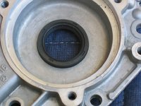
Next, it was time to press in the second seal into the driver's side cylinder head cover, which I'd finished cleaning up on Saturday. Our yellow lab, Chase, decided to catch some rays in the May sun. I'll show a little overview of the job here, seeing as I wasn't able to catch the passenger side because my digital camera had broken.
IMG_9335.jpeg IMG_9336.jpeg IMG_9337.jpeg


Press the seal in with your fingers as far, and as evenly, as you can. I then took a 30mm impact socket, and used it as a mandrel to drive in the seal to the desired depth. Hitting the edge of the socket in measured blows, evenly around its perimeter, helps make pretty short work of the job.
IMG_9338.jpeg IMG_9339.jpeg IMG_9340.jpeg IMG_9341.jpeg


Then I turned my attention to the airbox itself. I wanted to do two jobs -- one to replace the air filters, and the other job to replace the rubber ring that seals the round bottom "exhaust" portion of the airbox to the top of the MAF on the engine.
IMG_9342.jpeg IMG_9343.jpeg


Unclipping the sides of the airbox revealed the dual Mann air filters. They were not that dirty, and my date notation on them shows that they had last been replaced in April, 2016 .... so just over four years ago. Nevertheless, I replaced them with new Mann filters, which I also added the day's date to for future reference.
IMG_9344.jpeg IMG_9345.jpeg IMG_9346.jpeg


I then turned my attention to the rubber center sealing ring. This is a VERY overlooked rubber part on the engine. Given that it's about a $7.00 part, it's pretty much a no-brainer to replace it. It provides a seal so that unfiltered air does not enter the MAF and engine. The seal is just pressed on with the fingers, so it lifts off pretty easily.
IMG_9347.jpeg IMG_9348.jpeg IMG_9349.jpeg IMG_9350.jpeg


Once removed, you can see that the rubber was so fossilized that just the act of removing it, put a large crack in it.
IMG_9351.jpeg


Pressing the nicely pliable new seal into place. Much better......
IMG_9352.jpeg


The last small task for the day was to clean up the exterior of the EGR valve, and mount it onto the intake manifold with a new gasket. Three 5mm bolts hold the EGR valve onto the manifold. This also was a quick task, once everything lined up correctly. The intake manifold is now 100% ready for re-installation onto the top of the engine.
IMG_9353.jpeg IMG_9354.jpeg IMG_9355.jpeg IMG_9356.jpeg
 
I then turned my attention to the rubber center sealing ring. This is a VERY overlooked rubber part on the engine. Given that it's about a $7.00 part, it's pretty much a no-brainer to replace it. It provides a seal so that unfiltered air does not enter the MAF and engine. The seal is just pressed on with the fingers, so it lifts off pretty easily.
View attachment 103170 View attachment 103171 View attachment 103172 View attachment 103173


Once removed, you can see that the rubber was so fossilized that just the act of removing it, put a large crack in it.
View attachment 103174


Pressing the nicely pliable new seal into place. Much better......
View attachment 103175

Just to add, I would caution anyone who attempts this repair to survey the condition of the old seal carefully. I say that because I have found more than one that was so fossilized that when removal was attempted it broke off or cracked the plastic "ring" on the airbox that it fits over.

If you attempt to pry it off you'll damage the airbox mounting ring, seen below the seal in the 4th photo. If your seal is so hard you can't pry it off without a great deal of force, I suggest using a pair of diagonal pliers and "nipping" the edges of it carefully to cause it to crack into small pieces. It's a bit time consuming, but by taking this approach you don't risk permanently damaging the opening to the airbox.

The difference it makes is palpable - you'll know it when you put the air box back into place.

Dan
 
Finished with work about 5 PM today, so decided to head out to the shop for about 90 minutes to get some stuff done. Started a few tasks that have been on the overall project list.

The first task was to remove the upper and lower wiring harnesses from where they connect behind the CAN box. I wanted to remove the upper harness because it was otherwise totally disconnected, and the lower wiring harness because it needed replacement (it was the original harness to the car).

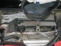
The first step was the remove the black plastic flat plate that covers and protects the connections for the lower harness. This is held by two clips, and after the clips are released, the cover can be pivoted out of the way, as shown below. This exposes the wire connections for the upper end of the lower wiring harness.
IMG_9364.jpeg IMG_9365.jpeg


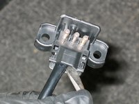
Next, I unclipped and unplugged the small connector for the lower wiring harness. I also had disconnected the large connector for the end of the upper wiring harness, and moved it out of the way. The small three-prong connector pulls straight rearward. Use an 8mm socket (I used a tall socket on a flexible extension) to remove the the small ring connector of the lower wiring harness. Use a 17mm socket on an extension and swivel socket or extension to remove the large ring connector. Use a 5mm Allen socket to remove the two bolts that hold the three-prong connector to the back of the CAN bus box.
IMG_9366.jpeg IMG_9367.jpeg IMG_9368.jpeg IMG_9369.jpeg IMG_9370.jpeg IMG_9371.jpeg IMG_9372.jpeg


I also loosened the ring clamp for the CAN box ventilation hose, and remove the hose, to make more room in the area, as shown below.
IMG_9373.jpeg


Then I was able to move the top end of the upper wiring harness out of the inner firewall into the engine compartment, and remove the UPPER wiring harness from the car.
IMG_9374.jpeg


Here's what a (replacement) upper wiring harness looks like, next to the much simpler (replacement) lower wiring harness.
IMG_9375.jpeg


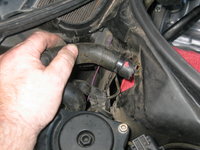
Next, I loosened the clamp on the coolant hose that leads from the rear of the block. I used a long screwdriver to loosen the clamp, as below.
IMG_9376.jpeg


The other end of the hose clamps to a riser on the back side of the passenger side of the engine block. This is what the hose looks like at the back of the engine. Loosening the clamp and then working the hose off of the riser, showed some crud and corrosion on the riser.
IMG_9377.jpeg IMG_9378.jpeg IMG_9379.jpeg


After loosening and removing the hose from the riser, I worked it through the inner firewall, and then removed it from the end I'd loosened a few minutes earlier. I also removed what I call "the Jaws of Life" -- the hinged plastic piece that holds the hose and the two wiring harnesses safely in place as they pass through the inner firewall. I later cleaned up the Jaws of Life.
IMG_9380.jpeg IMG_9381.jpeg IMG_9382.jpeg


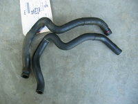
Here is the replacement hose (bottom) next to the original heater hose (top).
IMG_9383.jpeg


A few more views and comparisons of the ends of the old and new heater hoses.
IMG_9384.jpeg IMG_9385.jpeg IMG_9386.jpeg


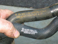
MB inscriptions on the old (top) and new (bottom) heater hoses.
IMG_9387.jpeg


Next, I tool some brake cleaner and a Scotch Brite pad, and cleaned up the riser at the rear of the engine. It cleaned up decently from its formerly dirty and corroded state.
IMG_9388.jpeg


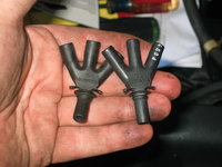
The next job was to replace the "Crow's Foot" -- the three-way vacuum connector running from one of the intake manifold vacuum nipples to the one-way vacuum valves and lines under the windshield. This is a $5.00 part, and a good idea to replace "while you're in there."
IMG_9389.jpeg IMG_9390.jpeg


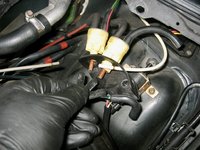
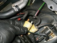
If you don't believe me, take a look at the "enlarged" holes on the old crow's foot, as compared to the small apertures on the new connector, Which one do you think is going to provide a better vacuum seal for the next 20-25 years? The second photo shows the new crow's foot installed. The grayish vacuum input line is not connected, because I'm going to replace it where it runs through the firewall from the engine compartment.
IMG_9391.jpeg IMG_9392.jpeg


Next to the last task, was to replace the spring-steel clips on the valve covers. These often go AWOL, and many owners don't even know they are missing! They press on to little tabs. I used a ball-peen hammer to carefully tap them into place.
IMG_9393.jpeg IMG_9394.jpeg IMG_9395.jpeg


Last task for the night, I came into the house to do at the table. I wanted to install the new rubber oil seals onto the new plastic MB top timing chain guides. I had installed new top chain guides some years back, when I replaced my plastic cam oiler tubes with metal ones, but I transplanted the original rubber seals onto the new top guides. This time, when I replace the top guides (when I replace the upper timing chain rails), I will have new rubber seals installed on them. These are the steps below where I added the rubber seals to the new top chain guides.
IMG_9396.jpeg IMG_9397.jpeg IMG_9398.jpeg IMG_9399.jpeg IMG_9400.jpeg
 
Gerry,

First, You are doing an outstanding job of documenting all of this work. Thanks for your effort. :thumbsup2:

Next. I just wanted to know where exactly is that flat plate in your first pic in the last post #157? Your pic is a great close-up but I can't relate it's location without a backed off shot from further away.:hammerhead:

I already have the upper harness and will be purchasing the lower harness. Anyway, I have never really looked for that connection. Just wondering where it was.

Also I will have to replace those heater hoses while I'm doing my refurbishment. I can certainly see how much tougher it will be for me without removing the intake manifold. If I can find them I already have some of the crows foot vacuum connectors and others along with the tubing. They are leftovers from working on my 84- 500SL

Anyway, please keep up the great work. I for one will be referring to it a lot.
 
The flat plate is in the recess behind the CAN box, or "coffin box" with the ECUs, just to the right of the right side hood hinge as you look towards the firewall. If you look back there you'll see it if it's not covered with detritus like leaves and pine needles. You'll see the wires going into the area below it.

Don't remove this unless the battery is disconnected, either.

Dan
 
Dan is correct. The flat plate is immediately BEHIND the CAN box and directly under/below the windshield and water drain tray area on the passenger side.

The good thing is that the lower harness only has three connections there. The upper harness has two connections.

I now have to get under the car to finish removing the lower wiring harness. I will probably feed the top end of the new harness up from below the car.

I do not think I would even attempt to remove/replace either side heater hose without first removing the intake stack from the car. It’s probably BARELY do-able, but the effort (though still considerable) is reduced probably by 80%.
 
About four hours out in the shop today -- 3.5 of it working on the removal of the lower wiring harness.

Before I got started on the wiring harness, I did a quick check on my oil separator. Yep, everything was there, and intact......
IMG_9401.jpeg


Until I pulled up on the rubber hose. Crack! Oops, the nipple on the plastic separator cracked off inside of the rubber funnel hose. Thankfully, I've got brand-new spares, so I'll replace them upon re-assembly.
IMG_9402.jpeg IMG_9403.jpeg


You can see how pliable the rubber funnel hose is .... not very. I'll do a comparison shot with the new one in the near future. Into the "junk" parts wastebasket it goes!!
IMG_9404.jpeg


Next, it was time to turn my attention to the lower wiring harness removal. First, I loosened and removed the plastic cover for the old (original) lower wiring harness. You can see the condition of the wiring for yourself.
IMG_9405.jpeg IMG_9406.jpeg IMG_9407.jpeg


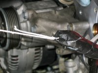
I attached a fishtape consisting of a thin rope to the ring on the end of the old harness.
IMG_9408.jpeg


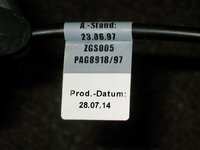
Then, with the new harness, I prepared it for installation. First, a few views of the new harness, including the front and back of the label.
IMG_9409.jpeg IMG_9410.jpeg IMG_9411.jpeg


Same as with the old connector, I prised apart the new connector, and removed it. I also took care to record the order of the three wires in the connector, for when I re-assemble it.
IMG_9412.jpeg IMG_9413.jpeg IMG_9414.jpeg


After removing the connector, I slid the transmission dipstick mount eyelet off of the cable, as I won't need it. The fishtape is designed to pull the new cable back up through the old transmission mount eyelet, which stays in place and needn't be removed.
IMG_9415.jpeg IMG_9416.jpeg IMG_9417.jpeg IMG_9418.jpeg


Here are the first views of the ends of the lower wiring harness connectors, as viewed from underneath the car. You can see the two alternator connections, and the oil pressure sender. The oil level sensor is just out of view, but it is nearby.
IMG_9419.jpeg IMG_9420.jpeg


To remove the alternator connections, remove the plastic cap and set it aside.
IMG_9421.jpeg


Then use a 13mm socket on the nut, and loosen it. Be sure not to miss the spring washer behind it! Slide the ring connector off of the post on the alternator.
IMG_9422.jpeg IMG_9423.jpeg


For the second alternator connection, you'll need an 8mm socket to remove the small nut and lock washer. Remove them.
IMG_9424.jpeg IMG_9426.jpeg


Use the end of a long screwdriver tip to prise off the single pole connectors on the oil pressure sender, and the oil level sensor on the lower part of the block. They should come right off.
IMG_9427.jpeg


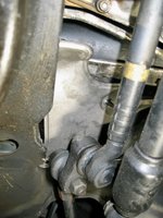
Next, you'll need to remove the last two connections at the starter. These are fairly difficult, and require some work. You will have to remove two heat shields above the passenger side tie rod and idler arm area, to get at the starter. One of the heat shields attaches to the starter itself, using two 10mm bolts and a 10mm nut. You have to get a bit creative with extensions and wobbly sockets to get all of these, but they are do-able with a little effort.

Here is the first of the two heat shields that you have to loosen and remove.
IMG_9428.jpeg


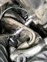
Here is the starter exposed. You can see the two connectors just to the left of the Bosch sticker in the photo below. One is a 13mm nut and washer, for the wiring harness' L-shaped connector, and the other connector is a small ring terminal that is connected to the starter with a Philips head screw. The 13mm nut takes some effort to remove, but is do-able with patience and persistence.

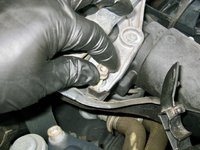
This Philips head screw is EXCEEDINGLY difficult to remove, as you don't really have the horizontal clearance to get a decent sized screwdriver up there, and you can't get enough leverage on a stubby screwdriver to loosen it. I ended up using a right-angle ratcheting screwdriver to loosen it. I was under the car for a good 45 minutes, staring at this nut, and racking my brain about how to remove it. FINALLY I remembered that I had the ratcheting right-angle screwdriver, and this with a bit of effort did the trick. I was JUST able to get enough of a purchase on the screw-head to get it. It's actually worth considering replacing this screw with an Allen screw.
IMG_9429.jpeg


In any case, the whole, entire time I was removing the harness, loosening connections, and pulling it down and out of the engine bay, it was literally RAINING DOWN small flakes, pieces, and flecks of wire insulation, corrugated connector, and other plastic parts from the harness. It literally crumbled and disintegrated before my eyes. There is no question it was WAY overdue for replacement, and I should have done this job years ago.

Here are a few views of the harness, after final removal from the car. I will install the new harness and complete this job in the near future.
IMG_9430.jpeg IMG_9431.jpeg IMG_9432.jpeg

Lower wiring harness removal is a job that all owners should do once in their lives, but ONLY once. It is a curse of a job. Really folks -- NOT a very fun job.
 
About four hours out in the shop today -- 3.5 of it working on the removal of the lower wiring harness.

Before I got started on the wiring harness, I did a quick check on my oil separator. Yep, everything was there, and intact......
View attachment 103624


Until I pulled up on the rubber hose. Crack! Oops, the nipple on the plastic separator cracked off inside of the rubber funnel hose. Thankfully, I've got brand-new spares, so I'll replace them upon re-assembly.
View attachment 103625 View attachment 103626


You can see how pliable the rubber funnel hose is .... not very. I'll do a comparison shot with the new one in the near future. Into the "junk" parts wastebasket it goes!!
View attachment 103627


Next, it was time to turn my attention to the lower wiring harness removal. First, I loosened and removed the plastic cover for the old (original) lower wiring harness. You can see the condition of the wiring for yourself.
View attachment 103628 View attachment 103629 View attachment 103630


I attached a fishtape consisting of a thin rope to the ring on the end of the old harness.
View attachment 103631


Then, with the new harness, I prepared it for installation. First, a few views of the new harness, including the front and back of the label.
View attachment 103632 View attachment 103633 View attachment 103634


Same as with the old connector, I prised apart the new connector, and removed it. I also took care to record the order of the three wires in the connector, for when I re-assemble it.
View attachment 103635 View attachment 103636 View attachment 103637


After removing the connector, I slid the transmission dipstick mount eyelet off of the cable, as I won't need it. The fishtape is designed to pull the new cable back up through the old transmission mount eyelet, which stays in place and needn't be removed.
View attachment 103638 View attachment 103639 View attachment 103640 View attachment 103641


Here are the first views of the ends of the lower wiring harness connectors, as viewed from underneath the car. You can see the two alternator connections, and the oil pressure sender. The oil level sensor is just out of view, but it is nearby.
View attachment 103642 View attachment 103643


To remove the alternator connections, remove the plastic cap and set it aside.
View attachment 103644


Then use a 13mm socket on the nut, and loosen it. Be sure not to miss the spring washer behind it! Slide the ring connector off of the post on the alternator.
View attachment 103645 View attachment 103646


For the second alternator connection, you'll need an 8mm socket to remove the small nut and lock washer. Remove them.
View attachment 103647 View attachment 103648


Use the end of a long screwdriver tip to prise off the single pole connectors on the oil pressure sender, and the oil level sensor on the lower part of the block. They should come right off.
View attachment 103649


Next, you'll need to remove the last two connections at the starter. These are fairly difficult, and require some work. You will have to remove two heat shields above the passenger side tie rod and idler arm area, to get at the starter. One of the heat shields attaches to the starter itself, using two 10mm bolts and a 10mm nut. You have to get a bit creative with extensions and wobbly sockets to get all of these, but they are do-able with a little effort.

Here is the first of the two heat shields that you have to loosen and remove.
View attachment 103650


Here is the starter exposed. You can see the two connectors just to the left of the Bosch sticker in the photo below. One is a 13mm nut and washer, for the wiring harness' L-shaped connector, and the other connector is a small ring terminal that is connected to the starter with a Philips head screw. The 13mm nut takes some effort to remove, but is do-able with patience and persistence.

This Philips head screw is EXCEEDINGLY difficult to remove, as you don't really have the horizontal clearance to get a decent sized screwdriver up there, and you can't get enough leverage on a stubby screwdriver to loosen it. I ended up using a right-angle ratcheting screwdriver to loosen it. I was under the car for a good 45 minutes, staring at this nut, and racking my brain about how to remove it. FINALLY I remembered that I had the ratcheting right-angle screwdriver, and this with a bit of effort did the trick. I was JUST able to get enough of a purchase on the screw-head to get it. It's actually worth considering replacing this screw with an Allen screw.
View attachment 103651


In any case, the whole, entire time I was removing the harness, loosening connections, and pulling it down and out of the engine bay, it was literally RAINING DOWN small flakes, pieces, and flecks of wire insulation, corrugated connector, and other plastic parts from the harness. It literally crumbled and disintegrated before my eyes. There is no question it was WAY overdue for replacement, and I should have done this job years ago.

Here are a few views of the harness, after final removal from the car. I will install the new harness and complete this job in the near future.
View attachment 103652 View attachment 103653 View attachment 103654

Lower wiring harness removal is a job that all owners should do once in their lives, but ONLY once. It is a curse of a job. Really folks -- NOT a very fun job.
Yes multiple Universal's needed...been there! And BEER!
 

Attachments

  • IMG_20200423_131637164.jpg
    IMG_20200423_131637164.jpg
    5.8 MB · Views: 33
  • IMG_20200423_132140516.jpg
    IMG_20200423_132140516.jpg
    3.7 MB · Views: 29
  • IMG_20200423_153404289.jpg
    IMG_20200423_153404289.jpg
    5.7 MB · Views: 28
One thing that I have been noodling on for the past couple of days, is the condition of the two yellow and gray vacuum valves near the fuse box. When I replaced the crow's foot a couple of days ago, the valves looked old and worn, and very tired on the outside. One of the two valves was missing its yellow retaining nut/cap, and the other valve's retaining nut was not in good condition and cracked.

[500Eboard] IMG_9389.jpeg [500Eboard] IMG_9392.jpeg

So (like I did some years ago with my 560SEC), I decided to replace these items to help optimize operation of the vacuum system.

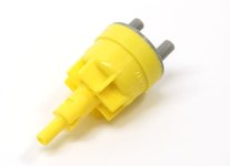
The "one to two-way" vacuum check valves are available from MB, part number 126 800 00 78. Two of them are required, and they are around $22 apiece.

Screen Shot 2020-05-17 at 9.02.14 AM.jpg Screen Shot 2020-05-17 at 9.02.07 AM.jpg

The retaining nuts (MB part number 126 805 00 99) are NLA. I have a couple of them in my parts stash from my 560SEC days, but also decided to try to round up a few online, and was successfully able to. They should be here next week.

Screen Shot 2020-05-17 at 8.54.48 AM.jpg Screen Shot 2020-05-17 at 8.58.11 AM.jpg

I will replace these vacuum valves when I have all of the part in hand. I have put the two valves on my next order from MB Annapolis.
 
One other item, affiliated with properly securing the lower wiring harness, is the plastic cable clip that presses into a hole in a plate near the oil filter housing. This cable clip secures the lower harness as it traverses downward toward the starter and alternator connections. With age and heat cycles, this clip gets hard and very brittle, and warrants replacement. When I prised it apart with a flat-blade screwdriver, it crumbled and fell apart immediately.

This clip is difficult to find in the MB parts diagrams, but it is part number 000 995 74 44. I ordered two of them, but for the lower wiring harness, you will only need one of them. It is available for around ~$3.50 from the normal discount MB parts dealers.

Just another heads-up for an item that you will need for your parts list, when replacing the lower wiring harness.

Screen Shot 2020-05-17 at 10.52.53 AM.jpg Screen Shot 2020-05-17 at 11.01.20 AM.jpg
 
This afternoon I spent about 90 minutes out in the shop. My singular goal was to get the lower wiring harness threaded up through the engine compartment and into position. I'm happy to say that with a bit of rest and refreshment, I was successful.

Yesterday, I tried to thread it up through the transmission dipstick cable eyelet, but the twine I was using was too thin, and could not take the upward force required to pull the harness up through the eyelet, so the twine snapped.

Today, I resolved to remedy the situation. Seeing as my fish-tape had snapped, I needed to create a new fish-tape. I used a four-foot length of speaker wire -- which was rigid enough, yet flexible enough, for me to work it up in the wiring harness path and up through the dipstick eyelet from underneath the car. I was able to do this in pretty short order.

Then, I re-jiggered the end of the wiring harness, by attaching a four-foot length of 1/4" nylon rope (good for 200 lbs of pulling force) to the ring on the end of the cable's main negative lead. Instead of bending the other small connectors back 180 degrees, I took electrical tape and kept everything pointing forward, and wound it all together into the very smallest and thinnest possible profile.

I attached the OTHER end of the 1/4" nylon rope to the end of my speaker wire underneath the car. Then I carefully started pulling the speaker wire up through the eyelet, in the engine compartment. Pretty soon, I could see the end of the nylon rope, where I had connected it to the end of the speaker wire.

I got underneath the car, and carefully fed the end of the lower wiring harness (where I'd wound the tape at the large ring connector) up and into the end of the transmission dipstick eyelet. I fed more lower wiring harness cable loosely along the path it traverses across and then upward toward the eyelet, to provide some slack. Then I got up again, and pulled a foot or so of the nylon rope into the engine compartment. I could then see the taped end of the lower wiring harness, where it had come through the transmission dipstick eyelet !! Success !

Alternating two or three more times between being underneath the car and in the engine compartment, I pushed (from below) and pulled gently (from above) until I got the proper amount of wiring harness into the engine compartment.

This process, including removing the old tape from yesterday and re-connecting and taping the nylon rope, speaker wire and lower harness together, and pulling everything up and through, took me about an hour, taking my time. It actually went pretty smoothly.

My photos pick up here, right after I finished pulling the lower harness up into the engine compartment.

The first step I did, after unwrapping/untaping the end of the wiring harness to expose the connectors, was to re-insert the three pins into the plastic pin bushing connector that goes behind the CAN box. This was easy enough, as you can see in the first photo. Be sure to insert them in the correct sequence as you removed them!! I referred to my photo from yesterday to ensure I got everything correct. The second photo shows the connections and the label of the lower wiring harness, sitting on top of the passenger side cylinder head (covered in shop towels for protection).
IMG_9433.jpeg IMG_9434.jpeg


I also took a couple of photos of the broken cable clamp that I mentioned holds the lower harness in the vertical position near the alternator. I have two of these clamps on order.
IMG_9443.jpeg IMG_9444.jpeg


The next task was to replace the heater hose that goes through the inner firewall from the riser at the back of the engine block. This hose has to be replaced BEFORE the lower and upper wiring harnesses are threaded through the inner firewall. The hose and harnesses correspond with the holes in the "Jaws of Life."

First, to make more room to work, remove the 10mm nut that holds the ETA plug to the front of the CAN box. This will make the following steps much easier. Get the hose into position and in the correct orientation, and insert it through the large hole in the inner firewall.
IMG_9435.jpeg IMG_9436.jpeg IMG_9437.jpeg


On the end of the hose on the CAN box side of the inner firewall, place the ring clamp into position (loosely). Since this is a new hose, I took a little bit of light oil on the end of a Q-tip, and coated the inside of the end of the hose, and the outside of the hose fitting, to assist sliding it onto the fitting.
IMG_9439.jpeg IMG_9438.jpeg


Tighten the hose clamp with a 6mm socket, or a flat-blade screwdriver (the 6mm socket works better, on an extension), after sliding the hose fully onto the fitting and ensuring its connection is solid.
IMG_9440.jpeg


After the hose clamp is tightened, use the 10mm socket to tighten the ETA connector bracket to the front of the CAN box, as shown in the photos.
IMG_9441.jpeg IMG_9442.jpeg


Push the end of the hose into place, and connect the other end of the heater hose to the riser at the back of the engine block. Again, a 6mm socket on an extension helps tighten the hose clamp, easily.
IMG_9445.jpeg IMG_9447.jpeg IMG_9446.jpeg


After the heater hose is connected at both ends, route the end connectors of the lower wiring harness through the inner firewall, directly on top of the heater hose. Start moving the wiring harness connectors into their general place, for installation. The second photo shows an overview of the area, with the heater hose and the lower wiring harness in place behind the CAN box.
IMG_9448.jpeg IMG_9449.jpeg


Next steps will be to connect the upper connectors and the alternator, starter, oil pressure and oil level connectors of the lower wiring harness in the engine compartment.
 
Gerry, another item to add to the "while you're in there" list... that auxiliary coolant pump motor, in front of the CAN box. After 25+ years, they start to get intermittent - have to whack them to make it run. Or they get noisy. I've had to replace that on almost every single one of my cars. Even if yours is OK now, it's only another ~$100... peanuts at this point.

:spend:
 
I’ll put one on tomorrow’s parts order from MB Annapolis.

I also ordered a spare passenger side motor mount cooling tube, for my deep parts stock. Passenger side is still available, to join the NLA-for-years NOS driver’s side cooling tube in my stock. Equivalent to the @Jlaa battery box sheet metal.
 
Check the price on OE! I think it's spendy. OEM Bosch is what I've been buying. Easy to swap while the cooling system is empty.

:rugby:
 
Gerry, another item to add to the "while you're in there" list... that auxiliary coolant pump motor, in front of the CAN box. After 25+ years, they start to get intermittent - have to whack them to make it run. Or they get noisy. I've had to replace that on almost every single one of my cars. Even if yours is OK now, it's only another ~$100... peanuts at this point.

:spend:
IIRC when I replaced mine, the best deal I found on it was actually the Bosch part in Amazon Prime.
 
IIRC when I replaced mine, the best deal I found on it was actually the Bosch part in Amazon Prime.

Be absolute positive it's the correct one if you're buying it on the Island of Large Wimmen. I ran into this problem with the circulating pump on my ML500 (W163). There are an amazing number of permutations of these pumps, and the variations are subtle, but enough to prevent them from fitting the hoses or connecting to the harness. The pictures all look the same, too...

Dan


I had a quick look --- the price seems to be better now at AutoHaus AZ / FCP Euro, at around $71, as opposed to BezosLand, where it is now $86.
 
More parts added to the bottom of the list.


Part NumberList PriceNet Price I PaidQuantitySourceOrderedNotes
119 200 15 0185.5085.501Pelican PartsJan-2018Graf water pump for M119.
119 201 03 805.255.251Pelican PartsJan-2018Genuine MB water pump gasket to engine.
120 997 03 466.506.502Pelican PartsJan-2018Elring crankshaft seal (ordered 2).
BM 116-0140114.95114.951Pelican PartsJan-2018Baum Tools M117/M119 crankshaft lock.
119 078 00 814.003.001MB AnnapolisApr-2018Crankcase vapor hose rubber elbow
102 094 02 122.401.752MB AnnapolisApr-2018Crankcase breather hose joint
119 094 02 124.503.381MB AnnapolisApr-2018Crankcase breather hose joint
119 094 03 1214.5010.751MB AnnapolisApr-2018Crankcase breather hose joint
119 094 26 8216.5012.131MB AnnapolisApr-2018Crankcase breather elbow hose
119 094 27 8219.5014.381MB AnnapolisApr-2018Crankcase breather hose
119 094 28 8240.0030.001MB AnnapolisApr-2018Crankcase breather hose
119 094 31 8228.5021.251MB AnnapolisApr-2018Crankcase breather hose
119 094 40 8220.0015.001MB AnnapolisApr-2018Crankcase breather hose
119 094 44 8228.5021.251MB AnnapolisApr-2018Crankcase breather hose
119 094 55 8233.5025.001MB AnnapolisApr-2018Crankcase breather hose
119 094 71 8233.5025.001MB AnnapolisApr-2018Crankcase breather hose
000 987 27 2710.507.882MB AnnapolisApr-2018Crankcase vapor hard plastic line. Superseded from 129 987 10 27
117 990 15 782.201.634MB AnnapolisApr-2018Crankcase breather hose joint
117 997 01 902.401.751MB AnnapolisApr-2018Breather hose clamp
126 997 06 900.700.501MB AnnapolisApr-2018Breather hose clamp
119 050 02 1619.5014.381MB AnnapolisApr-2018Timing chain rail - top
119 050 03 1622.0016.251MB AnnapolisApr-2018Timing chain rail - top
119 052 09 1614.5010.632MB AnnapolisApr-2018Timing chain plastic "comb" guide
119 052 11 1614.5010.632MB AnnapolisApr-2018Top timing chain rail - cylinder head
119 052 13 1664.0047.501MB AnnapolisApr-2018Timing chain slide rail, driver's side
119 094 45 8214.0010.251MB AnnapolisApr-2018Smog pump hose
119 094 46 8228.5021.251MB AnnapolisApr-2018Smog pump hose
119 094 47 8212.509.251MB AnnapolisApr-2018Smog pump hose
119 094 72 8224.5018.131MB AnnapolisApr-2018Smog pump hose. Superseded from 119 094 57 82
000 141 94 25379.00379.001RFC ElectronicsApr-2020Rebuild and test existing ETA by Don Roden
000 987 27 272.442.443AutohausAZApr-20203 meters Cohline large diameter black crankcase breather line
018 997 79 474.164.162AutohausAZApr-2020Elring M119 camshaft seals
119 141 26 8012.3912.391AutohausAZApr-2020Elring M119 intake manifold gasket, right side
119 141 15 809.719.711AutohausAZ
Apr-2020
Elring M119 intake manifold gasket, left side
HC 608091.681.682AutohausAZApr-2020Norma/Gemi MAF-ETA boot clamps. Ended up re-using MB clamps
000 158 14 351.871.8710AutohausAZApr-202010 meters Cohline vacuum line, white
119 142 08 801.941.941AutohausAZApr-2020Elring EGR valve gasket
116 200 03 1518.4918.491AutohausAZApr-2020Wahler thermostat for M117/M119
117 997 09 821.771.771AutohausAZApr-20201 meter Cohline black rubber vacuum line
124 682 07 2643.1343.131AutohausAZApr-2020GK W124 hood pad (without aluminum foil rectangle)
008 542 45 1716.1516.151FCP EuroApr-2020Beru two-prong coolant temp sensor at intake manifold
005 542 26 1727.5027.501FCP EuroApr-2020Beru one-prong coolant temp sensor at intake manifold
008 542 32 1720.6120.611FCP EuroApr-2020Beru four-prong coolant temp sensor at intake manifold
119 158 01 0261.0961.092FCP EuroApr-2020Beru M119 distributor caps
119 158 01 8845.3745.372FCP EuroApr-2020Bosch M119 distributor insulators
003 094 61 0411.2811.282FCP EuroApr-2020Two Mann M119 air filters
007603 0141040.050.053FCP EuroApr-2020Three Elring coolant temp sensor aluminum washers
601 078 02 456.754.801MB AnnapolisApr-2020Crankcase air hose joint
117 078 02 813.702.647MB AnnapolisApr-2020Black rubber vacuum hose connector. Superseded from 117 078 01 81.
119 078 00 813.902.761MB AnnapolisApr-2020
120 078 01 816.004.202MB AnnapolisApr-2020Superseded from 140 176 15 26.
117 140 02 659.006.008MB AnnapolisApr-2020Superseded from 117 140 02 65 64.
119 142 01 802.401.682MB AnnapolisApr-2020EGR pipe gasket at intake manifold
119 158 05 8521.0015.001MB AnnapolisApr-2020Black plastic surround for cam solenoids & distributors that mounts to front of cylinder head cover.
119 158 06 8519.5013.801MB AnnapolisApr-2020Black plastic surround for cam solenoids & distributors that mounts to front of cylinder head cover. Superseded from 119 158 03 85.
116 276 09 293.202.282MB AnnapolisApr-2020Plastic connector for crankcase vapor hoses
123 276 16 301.400.962MB AnnapolisApr-2020Plastic vacuum line
123 276 19 304.403.122MB AnnapolisApr-2020Plastic vacuum line
012 545 04 282.001.449MB AnnapolisApr-2020Plastic two-prong pin bushing housings
000 995 52 442.501.683MB AnnapolisApr-2020Drain hose clamp
000 995 58 44 641.501.081MB AnnapolisApr-2020Superseded from 000 995 58 44.
000 995 23 651.701.202MB AnnapolisApr-2020
000 995 66 654.903.482MB AnnapolisApr-2020Dual cable clip. Superseded from 115 995 03 65.
001 997 81 524.002.881MB AnnapolisApr-2020Superseded from 014 997 87 82.
002 997 24 90 642.401.682MB AnnapolisApr-2020Zip tie. Superseded from 001 997 83 90.
003 997 72 901.501.082MB AnnapolisApr-2020
040621 0082002.501.801MB AnnapolisApr-2020
040621 0102003.402.401MB AnnapolisApr-2020
040621 0162004.002.881MB AnnapolisApr-2020
119 200 03 85NLA49.921eBayApr-2020MB water pump reservoir **NLA**. Purchased from eBay vendor.
119 158 02 3132.4632.462eBayApr-2020Two Beru M119 distributor rotors. Purchased from eBay vendor. Difficult to find
B07PFQSXK714.9914.991AmazonApr-2020Fuel injector rebuild kit for Bosch fuel injectors.
FK3OV4-278.898.891AmazonApr-20203/4" drive, 27mm impact-rated socket for tightening M119 crankshaft bolt
20401314.8714.871AmazonApr-202010 feet of 1/4" Heatshield Products Hotrod Sleeve for underhood vacuum lines
20401223.7523.751AmazonApr-202010 feet of 1/2" Heatshield Products Hotrod Sleeve for underhood vacuum lines
2435074.3374.331Home DepotApr-2020Tekton 3/4" drive torque wrench with high torque capacity
111 051 00 439.506.722MB AnnapolisMay-2020Cam solenoid armature. Supersedes 104 051 04 43.
119 051 00 77109.0078.002MB AnnapolisMay-2020Cam solenoid. Must be paired with armature 111 051 00 43. Supersedes 119 051 01 77.
119 201 01 802.401.681MB AnnapolisMay-2020Water pump top housing gasket. Supersedes 117 201 01 80.
119 202 02 222.401.681MB AnnapolisMay-2020Belt tensioner round plastic cover. Supersedes 119 202 01 22.
119 203 03 825.503.961MB AnnapolisMay-2020Large diameter short top coolant hose between water pump top housing and intake manifold.
129 505 07 8627.0019.201MB AnnapolisMay-20201 meter, rubber seal between vertical side of radiator and radiator support. Supersedes 129 505 08 86.
124 830 54 9635.0025.201MB AnnapolisMay-2020Coolant hose between rear of intake manifold and heater core inlet.
124 830 76 9659.0042.001MB AnnapolisMay-2020Coolant hose between rear of block and coolant recirculation pump. Supersedes 124 832 64 93.
001 989 89 20 1034.5024.601MB AnnapolisMay-202050mL tube of orange anaerobic ("koala claw") sealant. Newly supersedes to 002 989 47 20 10.
000 990 44 921.200.843MB AnnapolisMay-2020Small plastic rivets that attach rubber seal that protects top of condenser to upper radiator support.
000 995 92 426.504.683MB AnnapolisMay-2020Black rubber 1-inch hose mounting clamp for high-pressure SLS line to oilpan area. Supersedes 000000 001045.
015 997 23 48 645.002.401MB AnnapolisMay-2020Extra round rubber thermostat gasket (M117/M119). Supersedes 015 997 23 48.
001481 0030312.101.464MB AnnapolisMay-2020Cam solenoid armature pins.
000 094 17 6010.007.081MB AnnapolisMay-2020M119 airbox rubber gasket around top of MAF.
104 990 10 043.202.282MB AnnapolisMay-2020M119 cam solenoid armature stretch bolts. Supersedes 914008 005000.
916016 0202014.403.123MB AnnapolisMay-2020Small gray 1/2-inch rubber cable clamps.
119 010 13 3034.5024.601MB NapervilleOct-2018M119 valve cover gasket, left. From parts stock.
119 010 14 3035.0025.201MB NapervilleOct-2018M119 valve cover gasket, right. From parts stock.
124 501 61 82117.0084.001MB NapervilleOct-2018Lower radiator hose to expansion tank. From parts stock.
220 997 16 5260.0042.601MB NapervilleOct-2018Transmission cooling hose, right side. From parts stock.
019 997 41 8267.0048.001MB NapervilleOct-2018Transmission cooling hose, left side. From parts stock.
007603 0061061.901.3218MB NapervilleOct-2018Copper valve cover washers. From parts stock (I have ~125 of them).
103 988 01 116.504.684MB NapervilleJan-2017Rubber intake box mounts. From parts stock.
1Transmission pan gasket. From parts stock.
1Elring transmission filter. From parts stock.
1Hengst oil filter. From parts stock.
1Mann power steering fluid filter. From parts stock.
1Behr radiator
119 010 00 627.005.041MB AnnapolisMay-2020Brown plastic MB oil separator for cylinder head.
119 016 03 8014.009.961MB AnnapolisMay-2020Rubber sealing gasket for brown timing chain top guide.
119 016 05 8013.009.121MB AnnapolisMay-2020Rubber sealing gasket for brown timing chain top guide.
119 016 01 8122.0015.601MB AnnapolisMay-2020Rubber "funnel hose" for oil separator in cylinder head.
119 094 00 934.503.242MB AnnapolisMay-2020Spring clips for valve covers, to help position and retain airbox when mounted atop engine.
201 805 02 227.255.161MB AnnapolisMay-2020"Crows-foot" vacuum connector for vacuum distributor located above brake booster / fuse box area.
104 990 00 222.902.046MB AnnapolisMay-2020Small screws used for mounting cam adjuster to end of intake cam. Due to FSM error, probably redundant and not needed for job.
126 800 00 7831.0022.202MB AnnapolisMay-2020Three-way vacuum valve located above brake booster, to replace original vacuum valves.
000 995 74 444.503.242MB AnnapolisMay-2020Plastic clamp for lower wiring harness near alternator.
000 995 80 443.702.642MB AnnapolisMay-2020Smaller version of plastic clamp per above, for deep-parts stock purposes.
124 520 02 0573.0052.201MB AnnapolisMay-2020Passenger side cooling pipe for engine mount, for deep-parts stock purposes.
 
I had a quick look --- the price seems to be better now at AutoHaus AZ / FCP Euro, at around $71, as opposed to BezosLand, where it is now $86.
Amazon used to almost always have the best prices on OEM Bosch parts... fuel pumps, aux heater pump, FPR, etc. But since COVID, they have jacked up their prices on some items, and tacked on 1-4 week delays. I've had a pair of fuel pumps in my Amazon cart for months (low priority proactive repair) and waited too long... finally gave up and ordered them from FCP, who still had pre-COVID pricing. RME was priced way over market on these for some reason.

Interestingly, Bezos has the aux pump for a decent price... currently $73, with 9-day PRIME Shipping.

FCP is still less at $71, and RME wants $77... beats OE at $316 list / $225 discount. (!!)
 
The passenger side motor mount cooling pipe is in Germany, and the rest of the parts that I ordered (cable clamps and vacuum valves) are in the Robbinsville, NJ warehouse. Should have everything by the end of this week.

I won't button up things under the car until I get the cable clip, but will re-connect the bottom (and upper) connections for the wiring harness, and in the meantime drain the transmission and torque converter, and replace the transmission filter. I will also replace the two transmission cooling hoses underneath the radiator area.

Next up is to remove the tandem pump mounting plate on the front of the engine, as I need to remove it so I can get at the two pins that hold the lower timing chain rail in place in the driver's side cylinder head. The other two timing chain rails' pins are accessible. This timing chain rail replacement will be the final job before I re-mount the cylinder head front covers and the valve covers. Then, I'll replace the water pump, re-clean the front of the engine (to make it even cleaner than the gsxr did with his), and basically stuff starts getting buttoned back up.

I'd say that things are at about the 55-60% mark overall right now. After the timing chain rail replacement, it'll just be a matter of slowly re-assembling everything. It will go MUCH faster, and most all of these new parts I've been accumulating (per the chart above) will start going on the car, lickety-split !!
 
Gerry, did MB Annap confirm the driver side cooling pipe (A1245200305) is NLA worldwide? All the RevParts sites are still showing it as orderable (which we know means nothing)....
 
Gerry, did MB Annap confirm the driver side cooling pipe (A1245200305) is NLA worldwide? All the RevParts sites are still showing it as orderable (which we know means nothing)....

For what it's worth the "funnel" on the front of the driver's side cooling pipe for the .034 shows as good in Paragon but no inventory either here or in Germany. As of Friday the item was still open on the order I placed a week ago. More as I know it.

Dan
 
I didn't bother to ask about the driver's side mount cooling pipe. Because I already have a NOS one I got years ago. I just wanted to complete my set, before the passenger side goes NLA (which we know it will, sooner or later).
 
:update: -- added photographs

Tonight I spent about 45 minutes out in the shop, doing a couple of tasks.

First, I reconnected the two connections for the top end of the lower wiring harness. I bolted the three-prong connector to the back side of the CAN box and plugged that electrical connector back on. I also took a small vacuum cleaner to the area to clean up the leaves and Texas pine needles, but I need to get out my big and powerful shop vac to really clean the area out.
IMG_9451.jpeg IMG_9452.jpeg IMG_9453.jpeg IMG_9454.jpeg IMG_9455.jpeg IMG_9456.jpeg


Next, I decided to remove the water drain setup underneath the windshield wiper. It was quite dirty, and one of the mesh grills had come loose, as the plastic welds had come apart. I have a couple of extras, so I’ll either fix what I have or replace with a spare.

i removed the cabin filters. They were filthy! I think the last time I’d replaced them, I was living in Portland, so it would have probably been about 2005 or 2006. I’ll have to look in my records.
IMG_9457.jpeg IMG_9458.jpeg

I have a new set of Mann cabin filters I’d bought back in 2014 in my parts stock, that I will install.

While the windshield drain is off, I’ll replace the foam weatherstripping on the underside, lubricate the windshield wiper arm — something I’ve never done to my recollection. And, of course, vacuum the whole area out.

Just made a bunch more work for myself tonight. I’ll post some photos later on, in the morning.
 
Last edited:
Tonight I spent about 45 minutes out in the shop, and started the next job -- the replacement of the three upper timing chain rails in the right and left cylinder heads. The left (driver's) side has two rails; the right (passenger) side has one rail.

To do this, I had to remove the smog pump, which I'd previous re-installed after replacing the hoses. This was so I could get to the two bolts that held the timing chain tensioner to the bottom edge of the cylinder head. This was exceedingly simple, because there are only three 13mm long bolts that hold the smog pump to the front of the block/front cover.

There are two fasteners that hold the timing chain tensioner to the head -- one 13mm bolt, and a 13mm nut and washer. The nut and washer are in an awkward position to access, because of one of the smog pump hoses. A few attempts to remove the nut with a 13mm box-end wrench resulted in me starting to round it off, so I got a 13mm flare nut wrench so that I could get a better grip on the nut and not round it off.

Here are a couple of views of the timing chain tensioner, before I began removing it.
IMG_9460.jpeg IMG_9461.jpeg


Removing the 13mm bolt....unfortunately I didn't take any photos of removing the nut with the 13mm flare nut wrench.
IMG_9462.jpeg IMG_9463.jpeg


And the tensioner comes away....
IMG_9464.jpeg


Here are a few views of the tensioner.
IMG_9465.jpeg IMG_9466.jpeg


And comparing the old tensioner with the new one. They are very very similar castings
IMG_9467.jpeg IMG_9468.jpeg IMG_9469.jpeg IMG_9470.jpeg IMG_9471.jpeg


Next, before I stopped for the night, I began removing the top timing chain guides. They are held in place by two 5mm Allen bolts, and several plastic clips. I just removed the first two bolts of the right-side guide, and will continue the process soon.
IMG_9472.jpeg IMG_9473.jpeg


As I was leaving the shop for the night, I took a quick photo of my old cabin air filters, mentioned last night.
IMG_9459.jpeg
 
Today, I received my vacuum valve retaining rings. These (as indicated) are NLA from MB.

Screen Shot 2020-05-20 at 11.31.14 AM.jpg Screen Shot 2020-05-20 at 11.31.39 AM.jpg


I was grateful to be able to find them. My vacuum valves should be here either tomorrow or more likely on Friday of this week. Note the production date of 2005, meaning these are 15 years old !!

CEAC710B-75B5-47BC-B6EA-58F8319F1515.jpeg
 
Tonight I had a pretty productive 2 hours out in the shop, after I shut down my work laptop for the long holiday weekend.

First task was to replace the two vacuum valves above the brake booster. This is a pretty easy and straightforward job. The old vacuum valves were dated June, 1993. The new ones were dated September, 2017. All were made in Germany.

Here's what things looked like, after I replaced the crow's foot. Notice that one of the retaining nuts is totally missing! The other one is not in good condition.
IMG_9474.jpeg IMG_9475.jpeg IMG_9476.jpeg IMG_9477.jpeg IMG_9478.jpeg


Comparison of old and new vacuum valves.
IMG_9479.jpeg


Removing the second of the two valves.
IMG_9480.jpeg IMG_9481.jpeg


Comparison of the old and new retaining nuts. These are the nuts that are NLA.
IMG_9482.jpeg


Installing and connecting the new valves. This was about a 10-minute job.
IMG_9483.jpeg IMG_9484.jpeg


Next up, it was time to replace the oil valve in the passenger side cylinder head. This was tough, because as you can see, part of the valve stuck in the head, though the larger part came out.
IMG_9486.jpeg IMG_9496.jpeg


Attempts to remove the small piece of the valve that was stuck in the head failed, and the small piece ended up disappearing down into the hole in the cylinder head. There is no way that I can get it, unfortunately. I hope that with the soft plastic, that it won't cause any damage or problems.

I used a short 1/4" socket extension as a mandrel, with soft hammer blows, to drive the new valve down into its position in the cylinder head. The second photo is the installed valve with the small rubber "funnel" hose on it.
IMG_9487.jpeg IMG_9488.jpeg


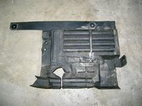
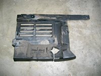
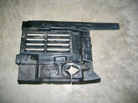
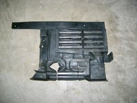
Next, it was time to continue connecting the connections of the lower wiring harness to the alternator and the starter. To make some room in doing this, I did the following: removed the passenger side motor mount cooling pipe (held by one 10mm nylon nut); removed the side engine compartment encapsulation barrier (and cleaned it up a bit); and loosened the steering shock's inboard connection, and pivoted it out of the way.

Here are two before and after photos from spending five minutes cleaning the passenger side encapsulation barrier. It is held with three 8mm screws to the car's frame.
IMG_9489.jpeg IMG_9490.jpeg IMG_9491.jpeg IMG_9492.jpeg


Then, I reconnected the two connectors at the alternator, which was fairly easy. I also pressed on the two single-pole connections of the harness at the engine oil level sensor, and the oil pressure sender. Again, these were very easy.

The last thing I did on that side, was to press in the plastic clip that holds the wiring harness where it drops down next to the oil filter canister. This was up there a ways, but was decently easy to reach from underneath the car. I was able to use a long, flat-blade screwdriver to snap the clip closed, after inserting the harness into the open clip. You can JUST see the clip in the photos below, of everything connected.
IMG_9493.jpeg IMG_9494.jpeg

Then I migrated over to the starter connections. By removing the 17mm nut and bolt that hold the steering shock to the car's undercarriage, I was able to make a bit more room to access the starter connections. I should have done this when removing the starter connections -- it would have resulted in a LOT less swearing! This is a tip for others who do replace the lower wiring harness -- make sure that you remove the inboard end of the steering shock, to make more room for your hands to get up to the starter connections.

I connected the large connection to the starter (13mm nut and washer), and began preparing the smaller, Philips head screw and lock washer. Around this time, I decided to wrap things up for the night, and continue tomorrow.

All in all, not a bad night, but I am a bit worried about the small piece of the oil breather valve that fell down into the head. Nothing I can do about it at this point, though :(
 
Next up, it was time to replace the oil valve in the passenger side cylinder head. This was tough, because as you can see, part of the valve stuck in the head, though the larger part came out.

Is this the part you're referring to (on the left)?
IMG_20200115_165021.jpg

From your picture, looks like locating dowel is missing. Did it remain in its nest, or did it end up in the neighboring nest, where the main part goes? Is this the reason why you had to tap new part in with a hammer, as the dowel caused an obstruction?
 
@gerryvz, where did you find them and is there more? :)
I did a product search via Google online and was able to find a couple of them. I am sure there are more out there, but I was only able to get two of them.

Is this the part you're referring to (on the left)?
View attachment 104078

From your picture, looks like locating dowel is missing. Did it remain in its nest, or did it end up in the neighboring nest, where the main part goes? Is this the reason why you had to tap new part in with a hammer, as the dowel caused an obstruction?
Correct -- it is the smaller projection that cracked off and remained in the cylinder head. This is not just a "locating dowel" though -- it is actually the piece that presses into the cylinder head and HOLDS the valve into position in the head. The smaller hole in the cylinder head is also serrated, and these serrations work with the serrations molded into the "locating dowel" to hold it in place.

I had to tap the piece into place with the socket extension so that the new part's serrated edges made proper contact with the serrations in the cylinder head hole. You can't just press the valve into place with your fingers -- it requires a bit more force to be pushed into place so that it stays in position. Does that make sense?

I could see via my work light that there was nothing in the hole and nothing that obstructed the new locating dowel from being pressed into place. The remains of the old locating dowel fell down into the cylinder head despite my tries with several tools, and a long wood screw (which I tried to screw into the top hole of the locating dowel) to pull it out.
 
I just realized this morning that I had not replaced the upper anchor for the lower wiring harness back onto the new harness after I'd installed it. So, I will need to remove all of the connectors behind the CAN box, and slide the new anchor onto the top of the harness. This anchor plate holds the harness to the rear of the passenger side valve cover, near the transmission dipstick.

Minor oopsie, and probably 15-20 minutes of work. :facepalm: But thankfully, I caught it before the upper wiring harness went back in the car on top of the lower harness :)
 
I have had nightmares early on with that kind of thing. IIRC, you busted my balls when I did something similar, I loosed the Upper harness support bracket while doing this job and as a result, some of the outer insulation rubbed off on the vibration near the bend of the secondary firewall near the curve prior to the clam shell. Anyway, glad you found it early on instead of "just in time" like me :D
 
I had to tap the piece into place with the socket extension so that the new part's serrated edges made proper contact with the serrations in the cylinder head hole. You can't just press the valve into place with your fingers -- it requires a bit more force to be pushed into place so that it stays in position. Does that make sense?

Yes, makes sense. When I did valve cover gaskets in January, in my case only the nipple on wich small rubber hose sits broke off (it stayed with the hose). I extracted remaining assembly in one piece with tweezers without any resistance. The new piece went in easily without any resistance too. My understanding, based on @JC220 guidance for that specific moment, was that the integral-to-passenger-valve-cover breather straw clamps the oil separator in place when reinstalled onto the head. Oh well...
 
Yes, makes sense. When I did valve cover gaskets in January, in my case only the nipple on wich small rubber hose sits broke off (it stayed with the hose). I extracted remaining assembly in one piece with tweezers without any resistance. The new piece went in easily without any resistance too. My understanding, based on @JC220 guidance for that specific moment, was that the integral-to-passenger-valve-cover breather straw clamps the oil separator in place when reinstalled onto the head. Oh well...

I dont believe this part requires hammering home no, especially given that it is held captive by the corresponding metal tube on the cam cover. Don't lose sleep over it, we may be slightly over thinking things here. Just a tad.
 
I dont believe this part requires hammering home no, especially given that it is held captive by the corresponding metal tube on the cam cover. Don't lose sleep over it, we may be slightly over thinking things here. Just a tad.

Mate, I'm alright. While Gerry is a beyond-any-doubt figure, so are You :D
 
When I pushed it in with my finger, there was zero resistance in pulling it back out. When I tapped it a few times to get the serrations down to meet the serrations in the head, there was resistance and it didn't easily come back up. Therefore, I opted for the slight resistance.

Don't misunderstand me -- I didn't "hammer" it down into the head. I gave it a few small taps.

If the piece was designed to sit there and solely be held in place by the valve cover tube, MB would not have put the serrations into the cylinder head (they almost look like threads), nor the serrations in the molded plastic piece itself. The serrations are there to help seat it, and keep it seated.
 
Saturday was a decently long day out in the shop, probably about 4.5 hours total. I got a lot done, so I'll document it here.

The first thing I did was to correct my "oopsie" as mentioned a couple of nights ago -- specifically, re-adding the upper bracket to the top end of the lower wiring harness. I had to remove all of the connectors behind the CAN box, remove the three-pin plastic connector, slide the upper bracket onto the top of the wiring harness bundle, and then re-install the plastic starter connector, and then re-connect the ring terminals and reconnect the three-pin plug into the starter connector. As said, this was about a 15-20 minute job. Not too big of a deal.

Secondly, I decided to take a diversion, and pursue a couple of "peripheral" tasks while I had fairly easy access to things. Specifically, this was the windshield wiper, and the water drain system at the base of the windshield. Working on both of these took me about 3 hours, but it was worth it given the results, and the correction of a few small issues that I found.

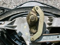
As far as I know, I have never lubricated the windshield wiper mechanism on the car, in the 18 years I have owned it. So, I decided to remove the wiper mechanism and clean it up, and at least lubricate the external joints. I did not remove the motor, nor did I remove and disassemble the internal gear mechanism -- I didn't see the point to do this, but certainly will if and when the time comes. However, the external rods and levers were all dry, and the center post that raises and lowers the wiper at the center of its arc was very much dry and in need of lubrication.

The wiper and motor mechanism is held onto the car with four 10mm nuts. These are all easy to get at -- two at the passenger side end, and two nuts parallel the to the ground on either side of the wiper's center pivoting mechanism. In the photos below, I am removing three of the four 10mm nuts.
IMG_9498.jpeg IMG_9499.jpeg IMG_9500.jpeg IMG_9501.jpeg


After removing the nuts, there is a metal spring clip in the center that binds the cast wiper mechanism to the car's structure. It is insulated via a rubber pad, which you can see inside the spring clip in the photos below.
IMG_9502.jpeg IMG_9503.jpeg IMG_9504.jpeg


After you remove the fourth 10mm nut (below), you can lift the entire wiper mechanism out of the car.
IMG_9505.jpeg


Here is what things look like with the wiper mechanism out. You can see that there is a little wear on the fresh air flap door -- some of the foam is worn away. There was a fabric covering over it that had fallen off, and was wadded up and sitting on top of the blower motor area. I need to think about what I need to do, in the future, to re-cover this fresh air flap door with new foam or covering, but that is a task for another day.
IMG_9506.jpeg


A few views of the wiper mechanism, as removed from the car. You can see plenty of dust and dirt adhering to the bottom of the mechanism, and motor area.
IMG_9507.jpeg IMG_9508.jpeg IMG_9509.jpeg


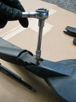
Next, you want to remove the wiper itself from the assembly. To do this (on later W124s), you lift/flip up the short cap at the base of the wiper. It should tilt up, and then you can remove it. This will expose a 5mm Allen bolt. This bolt is what holds the base of the wiper arm, to the pivoting wiper mechanism.
IMG_9510.jpeg IMG_9511.jpeg IMG_9512.jpeg


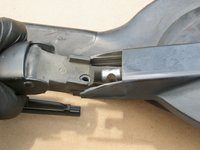
After you've removed the 5mm bolt, you can gently and slowly separate the wiper arm from the rotating mechanism by pulling steadily. It will come off with a few small back-and-forth wiggles.
IMG_9513.jpeg


After you've separated the wiper arm from the reset of the mechanism, you can lift off the large cap that covers the center of the mechanism. It snaps on from the two edges, and you can release it by running your fingers around the edges of the cap to release the plastic catches.
GSXR EDIT: This plastic cap is only used on late wipers, as of early 1994 USA model year production. Older models have a metal cap that *does not* snap off, it is fastened with screws from the back side, and is far more difficult to remove. My 07/1994 production E500 has the non-removable metal cap.
IMG_9514.jpeg


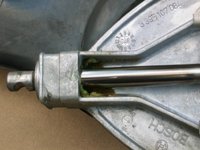
When the cap is removed, this is what you see -- the center post that extends the wiper arm up and down. You can see the old grease (yellow grease) on the sides of the post, where it goes through the housing. I spent the next 30 minutes removing all of the old grease, and then lubricating ALL of the pivot points and arms on the top and underside of the wiper mechanism with fresh synthetic grease, applied with a syringe to the exact points where it is needed.
IMG_9515.jpeg


After lubricating everything well, I set the wiper mechanism aside, so that I could tackle the next job -- the rebuilding and refurbishment of the water drain mechanism at the base of the windshield. I had removed this five-piece item a few days ago, and set it aside in the garage while I decided what to do with it. Over the course of a few days, I decided to totally refurbish it as best I could, as there were a couple of aspects to it that needed my attention.

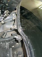
First, as you can see below, after removing the windshield wiper, you can see that where was A LOT of dirt and detritus at the base of the windshield, including in the plastic channel into which the rubber windshield wiper side-seals fit into. This led to a situation where my rubber side-pieces didn't press in and hold as well as they should. There was a lot of dirt, leaves, pine needles and other crud in the plastic channel. So, I got my shop vac out, and a thin flat-blade screwdriver, and I cleaned out the channels, and nearby leaves and dirt at the base of the windshield, and vacuumed it up with the shop vac. Doing this will help the rubber side pieces of the windshield wiper seat MUCH better once I re-install it. The two photos below show the sorry condition of the area, before I cleaned up the channels.
IMG_9516.jpeg IMG_9517.jpeg IMG_9518.jpeg


Next, I concentrated on the plastic water drain channels themselves. The channels' sealing edges to the inner firewall had some very old and sticky/dilapidated sealing foam. I removed this foam from the bottoms of the plastic water drain channels, and using some 1/4" adhesive foam that I purchased from Home Depot (Frost King brand, $6.49 for 10 feet), I rolled new foam into the positions where the old foam had been. On the inner firewall center piece (third and fourth photos below), there is a small thin slot into which foam had been pressed from the factory. I painstaking removed this pressed-in foam, and then pressed in (using a plastic screwdriver blade) a new length of foam.
IMG_9519.jpeg IMG_9520.jpeg IMG_9521.jpeg IMG_9522.jpeg IMG_9523.jpeg


I also had one broken piece of the water drain channels -- the passenger-side large piece. The plastic-welds had come undone on this piece, and this allowed the mesh screen to pop free. I don't know when this had happened, and while not 100% detrimental to the operation of the drainage system, I wanted to have the mesh screen properly affixed into place. So, I got a spare part out of my deep parts stock, cleaned it up, and then added foam to it (per the above steps).

I also had a side piece, on the driver's side (the side piece where the water drains along the bottom of the windshield and down into the side drain at the fender) that was missing one of the small flanges underneath that help secure it to the larger piece with the mesh screen. Again, not a 100% detrimental thing, as the side piece is well-secured to the car, but also not 100% correct and as the factory intended it. So I got a spare piece out of my parts stock, and replaced it. You'll see in a couple of minutes the importance of this "flange" that I mention.

Here's what the "refurbished" water drain system looked like, after I'd finished cleaning and re-sealing it. I basically cleaned it enough so that there was no loose dirt or crud on it -- not a concours-style cleaning. I just wanted to make sure it was 100% complete, intact, and functional again.
IMG_9524.jpeg


After working over the water drain channel system, it was time to begin re-instaling the freshly lubricated windshield wiper system. Installation is largely the reverse of removal -- four 10mm nuts, and the center clip
IMG_9525.jpeg IMG_9526.jpeg


After I re-installed the windshield wiper, it was time to renew the cabin filters. Before I did this, I took a plastic razor blade and removed some of the left-over old foam that had adhered to the top of the inner firewall. Then I took my shop vac, and gave the entire area a good Hoovering to pick up any leaves, foam pieces, Texas pine needles, and any other crap. This included the blower motor, inner firewall and cabin filter area. Then I installed the two cabin filters and seated them appropriately (one photo didn't totally turn out, sorry).
IMG_9527.jpeg IMG_9528.jpeg IMG_9529.jpeg IMG_9530.jpeg


Then I attached the center clip for the windshield washer mechanism.
IMG_9531.jpeg


Then it was time to begin re-installing the plastic water drain system. This is fairly easy with the windshield wiper mechanism installed -- although you do need to lift the bottom of the rounded rubber seal at the bottom of the wiper pivot up a little bit, so you can fit in the center part of the water drain system (as shown in the two photos below.
IMG_9533.jpeg IMG_9534.jpeg


From there, you just use your sheet metal screws to attach the center pieces to the car's body and firewall. There are 5-6 screws securing the two pieces. I popped the removable center drain back in.
IMG_9535.jpeg IMG_9536.jpeg IMG_9537.jpeg


Then it was time to add the side pieces. Each of these are held in by two sheet metal screws, and are attached similarly to the large plastic center pieces. Be sure to tuck the spouts at the ends of the side pieces into the rubber drain hoses below the corners of the windshield, when you are re-installing the side pieces !!
IMG_9538.jpeg IMG_9539.jpeg


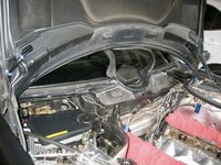
Here's what things should look like, with everything installed.
IMG_9540.jpeg


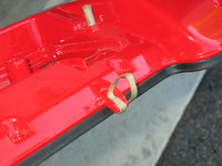
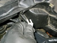
The last step is to add the white plastic pieces to the underside of the side/center pieces. Remember the "flange" on the side piece that I spoke about earlier? Well, each side piece has a small "T"-shaped flange that projects downward through a small hole in the end of the center piece. This flange helps secure the center and side pieces together using a "U"-shaped, white plastic clip, as shown below. On my car, BOTH of these clips were missing. Fortunately, I had three of them in my deep-parts stock, and I was able to re-install them by pushing them in over the flange, to lock the side and center pieces together. The third and fourth photos below, show the passenger and driver's side white clips installed. Note that these clips can be brittle with age, so be careful and DO NOT stress them. They push straight on, and if everything is properly aligned, they should push on quite easily.
IMG_9541.jpeg IMG_9542.jpeg IMG_9543.jpeg IMG_9544.jpeg


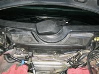
And, the finished product -- a completely re-furbished and re-installed windshield wiper and rain drain channel system. Something I've wanted to do for a long time.
IMG_9545.jpeg


The latter hour or so of my time out in the shop, was spent re-connecting the connections of the lower wiring harness to the starter, and re-installing the two heat shields that protect the starter and harness connections, and the passenger side tie rod and ball joint/boot, from the hot exhaust manifold and downpipe. Fortunately this was relatively straightforward. I had already installed the 13mm nut that held the wiring harness connector to the starter's large terminal, so all I needed to re-connect was the small Philips head screw that held the harness's solenoid wire to the starter. This took a bit of effort, but I eventually got it. One tip -- it's much easier to do this job of attaching the starter connections with a non-gloved hand, as you can get a better "feel" for things with a bare hand.

After tightening the connections, I re-installed the heat shields (two 10mm bolts with the tie rod heat shield; two 10mm bolts + one 10mm nut with the starter heat shield), and then re-attached and tightened the steering shock (17mm nut and bolt).

One thing I have found with the lower wiring harness, at least with mine. I had purchased my lower wiring harness back in 2014, when I was living in Texas. Since then, it has been in the original plastic bag that I received it in. However, in a couple of places, the outer rubber sheathing of the harness started cracking. Not the wiring or insulation -- but rather the outer shrink-wrapped plastic sheathing that surrounded the wires of the harness. To combat this, as I installed the harness, I wrapped the harness in these places in high-temperature, high-quality 3M electrical tape (I probably should have used the TESA fabric wiring harness tape) in the places where the sheathing was breaking down. I don't know why it did this, but it did. Doesn't look great, but it is what it is. Here in the below photo, you can see where I wrapped the harness with the electrical tape.
IMG_9532.jpeg


Don't know if anyone else has experienced this (or had a harness sitting on the shelf for 5-6 years like I did), but I'd be interested in any observations or experiences you may have about this. Again -- not detrimental in any way to the harness itself, but at the same time a bit disappointing. I didn't have the proper items at hand to heat-shrink the harness with new sheathing -- which in an ideal world would have been the best thing to do. We'll see how well my electrical tape fix works.

After doing all of that, I decided to call it a day. The next task will be to drain the torque converter and transmission, and replace the transmission fluid and filter. At the same time, I will replace the two transmission cooler hoses in at the front of the engine. After I finish the transmission service, I should generally be done with all of the required work under the car.
 
Gerry and others - a Martha tip:

10" Bamboo skewers like you would purchase to do shish kebab work great for loosening things in the cowl and other drain locations. You get a long reach, they're flexible, and won't damage metal or plastic since they're far softer. When I vacuum out cowl drains I like to use them to "agitate" the detritus that's collected so the vacuum cleaner can suction it out completely.
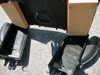
I just used one to clean a bunch of old leaves out of the lift support channels in my S210 wagon's rear hatch yesterday. These are deep enough that the vacuum cleaner tools can't reach all the way into the recess. By shaking the leaves and stuff around with one of these the resulting turbulence allowed the vacuum cleaner to suck them up.

Dan
 
Since I never mastered the usage of chopsticks, every time I go for Chinese food I bring home the chopsticks.
They are handy for reaching into confined areas, you can sharpen them to use as scrapers or zip tie pieces of
rags on the ends to scrub with.
 
I was pleasantly surprised to find pretty much zero dirt and debris in the water drain channels, hoses, and such. A few pine needles and leaves caught in the channel at the bottom of the windshield, and vacuumed out underneath the CAN box and brake booster areas. Otherwise, everything was pretty darn clean. I guess that is because the car is garaged most of the time, even when I lived in Texas.

I probably got the pine needles in the windshield base area from the times I visited @nocfn at his house and parked my car in his driveway.
 
@gerryvz such a detailed and informative writeup. What is this purple vacuum line, running laterally across the false firewall, that I keep on seeing? Is this something you added or did it come from the factory this way? I recognize the purple as a Mercedes part.....

1590336671357.png
 
That's a wire, not a vac tube... guessing it may be for the NOS solenoid? Not factory though.

There are purple vacuum tubes used for the factory headlight level adjustment though. Most people don't use them due to the ridiculous cost for a piece of plastic tube, $33 list each, x3 (link).

:nos:
 
That's a wire, not a vac tube... guessing it may be for the NOS solenoid? Not factory though.

There are purple vacuum tubes used for the factory headlight level adjustment though. Most people don't use them due to the ridiculous cost for a piece of plastic tube, $33 list each, x3 (link).

Correct. That is a wire for the nitrous-oxide solenoid.

HAHAHAHAHAHahahaha. I ask because I put the "ridiculous cost purple vacuum tube" in the exact same location - for the headlight level adjustment.

For you though, Gerry - 1590341539504.png
 
Back
Top