• Hi Guest !

    Welcome to the 500Eboard forum.

    Since its founding in late 2008, 500Eboard has become the leading resource on the Internet for all things related to the Mercedes-Benz 500E and E500. In recent years, we have also expanded to include the 400E and E420 models, which are directly related to the 500E/E500.

    We invite you to browse and take advantage of the information and resources here on the site. If you find helpful information, please register for full membership, and you'll find even more resources available. Feel free to ask questions, and make liberal use of the "Search" function to find answers.

    We hope you will become an active contributor to the community!

    Sincerely,
    500Eboard Management

OWNER LWB250 (E420)

Time to get some stuff done...

The third brake light overspray was making me crazy, so I removed the part from the car and began remediation.

1995 420E 05232020 - 1.jpg

I tried a number of things - shoe polish, sandpaper, wire brush, etc., all to no avail. Finally, I got a cotton swap and my go-to solvent, 3M 08984 General Purpose Adhesive Remover. This stuff is wicked and will remove just about any grease, adhesive, you name it, and it won't hurt painted surfaces. With some elbow grease and this I was able to remove the overspray. Ugh!

1995 420E 05232020 - 2.jpg

Now to even things out and make the surface look minty fresh I took some Mother's Back to Black and treated the affected areas.

1995 420E 05232020 - 3.jpg

And now to fix that torn rubber seal.

1995 420E 05232020 - 5.jpg

Back in the car like new!

1995 420E 05232020 - 6.jpg

And now to tackle the antenna. While I wasn't getting full extension on the mast, I figured it wouldn't hurt to open up the antenna to clean and lube the innards. Cover off and the insides don't look too bad. I've already taken the fasteners out of the guide.

1995 420E 05232020 - 7.jpg

Take the guide out and survey the pinch roller. Not bad, just a little dirty.

1995 420E 05232020 - 8.jpg

Disassemble and clean the pinch roller and guide. Much better!

1995 420E 05232020 - 9.jpg

Lubricate and reassemble, install in the car. We have antenna! Well, at least 2/3 antenna. Better than nothing.


1995 420E 05232020 - 10.jpg

And now onto the tool kit.

I have two tool kits, one from a W140 and one that came with the car. Neither fit as the "bucket" that holds the spare tire in place is not the one that will allow the tool kit to nest in it. One with the car on the left, W140 kit on the right.

1995 420E 05232020 - 11.jpg 1995 420E 05232020 - 13.jpg

Either way, I still wanted a tool kit in the car, so I got everything in the W140 tool kit that belonged there and put it in the trunk.

1995 420E 05232020 - 14.jpg

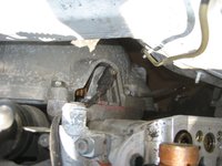
And now onto the repair of the day, replacing the leaking power steering reservoir hose.

As @RicardoD did a great DIY writeup on this repair already, I'm not going to bore everyone with the process. However, there were some things I wanted to detail for informational purposes.


I found that the hose on my car was cut too long, telling me that the repair has been done previously. Note the length and that the hose has a beveled spot on it from being too long and forced into the location.

1995 420E 05232020 - 16.jpg 1995 420E 05232020 - 17.jpg 1995 420E 05232020 - 18.jpg

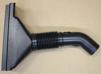
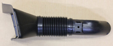
I have a ZF pump, so the length of the hose should be 53 mm. The old one was clearly longer, as you can see compared to the new hose.

With all of this in mind, don't be concerned that the hose appears to be too short. It will. I tried to get a picture of this but it's near impossible. If you look down the hole in the base of the reservoir you can see the gap between the hose and the base.

1995 420E 05232020 - 22.jpg

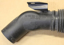
The length of the hose barb fitting that you thread into the base is quite long, so it will reach well beyond the base and into the hose itself, with the barbed portion of the fitting projecting well into the hose.

1995 420E 05232020 - 23.jpg

Don't forget the aluminum sealing ring!

And now with the hose in place and new clamps tightened down, it's time to reinstall the nice clean reservoir and plastic cover.

1995 420E 05232020 - 24.jpg 1995 420E 05232020 - 28.jpg

Another detail item you'll figure out but bears mentioning. The gasket for the reservoir base only fits in one direction.

1995 420E 05232020 - 29.jpg 1995 420E 05232020 - 30.jpg

All reassembled and ready for fresh fluid.

1995 420E 05232020 - 32.jpg

And done. A good day all in all.

1995 420E 05232020 - 33.jpg


Dan
 

Attachments

  • 1995 420E 05232020 - 29.jpg
    1995 420E 05232020 - 29.jpg
    170.9 KB · Views: 15
One other item that's not of great significance but makes me happy:

I found a complete owner's manual set with the leather folio for the model and year. It has everything in it down to the Roadside Assistance folder and dealer list, maintenance manuals, everything. Even has the service manager's card from the car's dealer. No radio code card, but that doesn't matter, as it wouldn't match anyway.

Dan
 
Great additional info to add to RicardoD's writeup. And a good nudge to get me to finally do this project. Thanks.
 
Great additional info to add to RicardoD's writeup. And a good nudge to get me to finally do this project. Thanks.

It's not a bad job to do, really. As long as you have the right tools, with the 12mm allen/hex probably being the most unusual one. Just some fiddly stuff with getting the old hose out and that's about it. I didn't completely remove plug wires, either, I just removed the cap and laid it out of the way, As a result I had to wrestle a little bit with the plastic cover, but it wasn't bad. The wire gutter that crosses the engine sits inside of it, so you have to do a little prying to get it loose. Otherwise, the rest is just removing and installing fasteners for the most part.

I took my time and I think with including the parts cleaning time it took me about 90 minutes total.

Dan
Love it. I can feel myself getting more motivated all the time. Finally!
 
Going to be a good day. Last night I found the bag of thermocouples that I've been looking for since I got the car. I'll be replacing the temperature sensor for the dash temperature display today, I expect. This is a pretty easy win and far simpler than replacing the whole cable and probe.

1995 420E 05242020 - 1.jpg

Dan
 
Well, these are good mousers! Read on!

As many of you have experienced, your exterior temperature indicator in the instrument cluster is haywire. If you gave it credence, the winds of the Arctic have descended on you or conversely, the Sahara, despite the appearance outside of it being quite pleasant. It's not the unit in the cluster, it's the thermocouple that is located below your front bumper. It's either failed or become wildly inaccurate as it's aged.

Looking into this, you'll find that for a princely sum Mercedes will sell you a new temperature probe, complete with cable that must be snaked through all manner of openings and grommets to reach the sanctum sanctorum of the dash and connect to the display unit. However, a fix is far simpler and cheaper. To-wit:

Locate your temperature probe. They're typically behind or just below the license plate insert on the front bumper. Some will be a metal probe with a mounting tab spot welded to it, others like the one shown here will have a metal clamp that holds the probe in place.

1995 420E 05252020 - 2.jpg

I was able to pry the clamp back and remove my probe. If you have one with the mounting tab you'll have to remove the fastener that holds it in place.

1995 420E 05252020 - 3.jpg

A close look at my probe showed that the insulation had cracked where it entered the probe's rubber boot or housing.

1995 420E 05252020 - 4.jpg

I cut the base of the boot/cover away to expose the thermocouple. You can see that I was able to remove the tip of the cover from the thermocouple. If you have the earlier type that's all one (metal) piece with the mounting tab, you'll need to simply cut the cable off of it and strip the leads. You can pull the guts out of it and install the new thermocouple inside.

1995 420E 05252020 - 9.jpg

And here's the thermocouple and the reason for it's lack of function is pretty clear.

1995 420E 05252020 - 7.jpg

Yup, a definite open circuit. I took the tip of the boot and cleaned it out with a cotton swab soaked in alcohol. It appeared that it was full of what appeared to be silicone grease. I guess that makes sense in that it would allow for better heat transfer to the thermocouple, but I'm going to install the replacement more or less "dry".

Here's the new thermocouple.

1995 420E 05252020 - 11.jpg

I should have put something in the photo for scale, but this device is about 2mm in diameter with leads about 5 cm long. I stripped about 1-2mm of insulation and tinned the leads of the cable after removing the old thermocouple from it. I also added a small piece of heat shrink tubing to one lead of the thermocouple to provide insulation. Using the boot and cable to determine how long the leads needed to be, I trimmed the leads of the thermocouple and soldered the lead with the heat shrink tubing on it.

1995 420E 05252020 - 13.jpg

Once the first solder joint has cooled, I moved the heat shrink down to cover the joint, then soldered the second lead. The heat of soldering the second lead shrank the heat shrink tubing for me on the other lead. Once both had cooled, I cut a small piece of black electrical tape and inserted it in between the leads to insulate the remaining exposed leads and wrapped it around to secure.

1995 420E 05252020 - 14.jpg 1995 420E 05252020 - 15.jpg

Crude but effective. With the leads insulated, I placed heat shrink tubing over the cable, then placed the boot over the thermocouple.

1995 420E 05252020 - 16.jpg

I heated the tubing to seal the boot to the cable. Another larger piece of heat shrink to seal the whole thing into a single unit.

1995 420E 05252020 - 17.jpg 1995 420E 05252020 - 18.jpg 1995 420E 05252020 - 19.jpg

I pulled the clip back and put the probe back in the clamp under the bumper.

Now for validation. Ambient temperature about 82 F. Note that I let things stabilize for about 30 minutes before I checked this. I say that because even five minutes after I had done the heat shrink and all that it was still reading 135F!

1995 420E 05252020 - 20.jpg

Dash says:

1995 420E 05252020 - 24.jpg

Success!

I bought four of these probably 4-5 years ago and if I recall correctly they were a few bucks apiece. Looks like the price has gone up slightly.

Mouser 527-1003-3K NTC Thermistor

Dan
 

Attachments

  • 1995 420E 05252020 - 16.jpg
    1995 420E 05252020 - 16.jpg
    58.5 KB · Views: 14
Last edited:
Mods - you're welcome to copy the previous post to the DIY section if you wish. I did my best to keep it on point so it would be suitable for inclusion as a DIY.

Dan
 
Busy week, next week will be even worse at work. Spent the morning at the pistol range with my former boss getting the cobwebs out of my grips and sending lots of lead down range. After I got home I had to spend some time cleaning everything, as I'm pretty much a Martha about my firearms like I am my cars.

With that out of the way and smelling like Hoppes #9, I took care of a few minor things on the 420E:

First was to place my "ALT NPS" sticker on the rear window. While I'm not big about putting stuff on my cars like stickers, the "ALT NPS" group are National Park Service employees who are using social media to protest the cuts being made to our national parks and the misuse of Federal lands. I have vested interest as one of my kids was an NPS employee at the Grand Canyon. They chose to return home and work as a County park ranger as they felt they could have a bigger impact on the environment here.

1995 420E 05302020 - 2.jpg

Next was a new(er) fuse box cover. I had one from a forum member that was better than the original as the original had a pivot broken off, but the replacement had some of that yellow Cosmoline-looking stuff on it and I couldn't clean it off. This one is cleaner, I'll put the other in my collection of spares for another car.

1995 420E 05302020 - 3.jpg

Speaker trim retainer thingy. Yeah, a technical term, no doubt. Someone had been into the left dash speaker and it appears they might have broken or boogered up the little trim piece that covers the retaining screws. This one wasn't as bleached from the sun, either. Old one:

1995 420E 05302020 - 4.jpg

New one below the original one:

1995 420E 05302020 - 7.jpg

I thought the original might have been damaged, but luckily it was OK. Another one for the spares supply.

Scoped out the mini sun visor that goes over the rear view mirror. My car has one of the cell phone controller boxes in it's place, which will be removed when I do the headliner and replaced with the visor. Looking forward to pulling that rearview mirror. Always a fun job...

1995 420E 05302020 - 5.jpg 1995 420E 05302020 - 6.jpg

I dry fitted, or planned on dry fitting, the "scoop" for the left front engine mount cooling tube. Discovered that I (still) don't have all the pieces. So much for that idea.

1995 420E 05302020 - 8.jpg

Tomorrow I'm planning on replacing the AC compressor. Not a job I'm looking forward to since it will be another Florida scorcher, but it's got to be done and I won't have AC in the garage for another month at the earliest. Since I'll have to drop the front sway bar as well, I'll be doing new sway bar bushings as well. Might as well since I'll be in the neighborhood.

So not a terribly productive car day, but progress nonetheless. Small steps.

Dan
 
Dan, yeah the left (driver) side scoop is two pieces before you get to the (NLA) air cooling hard-tube. The right side is only a single piece scoop that goes to the hard tube. They sort of attach differently to the front spoiler, as well. I just removed the driver's side two-piece scoop on my car the other day for soaking and cleaning (part of the anal-ness side tracking I mentioned in my latest post), so it's literally sitting out in my garage at the moment !!

Then I went full-anal and put together a parts order for new fender-liner screws, and plastic nuts for everything.....
 
I keep those fender liner screws and plastic nuts on the shelf as they're used across the board on a lot of different models. I'm amazed at how many I find missing when I get a new car...

Dan
 
Dan, yeah the left (driver) side scoop is two pieces before you get to the (NLA) air cooling hard-tube. The right side is only a single piece scoop that goes to the hard tube. They sort of attach differently to the front spoiler, as well. I just removed the driver's side two-piece scoop on my car the other day for soaking and cleaning (part of the anal-ness side tracking I mentioned in my latest post), so it's literally sitting out in my garage at the moment !!

Then I went full-anal and put together a parts order for new fender-liner screws, and plastic nuts for everything.....
Actually, I just took the driver's side scoop apart and performed a @lowman / @JC220 style clean to it. It is three parts, not two. The scoop itself; a flexible/corrugated connector piece, and a hard plastic elbow. The NLA hard pipe for the driver's side connects to the hard plastic elbow.
 
Actually, I just took the driver's side scoop apart and performed a @lowman / @JC220 style clean to it. It is three parts, not two. The scoop itself; a flexible/corrugated connector piece, and a hard plastic elbow. The NLA hard pipe for the driver's side connects to the hard plastic elbow.

I'm assuming those two pieces are (were) sold as an assembly as the EPC only lists one piece there.

Dan
 
I'm assuming those two pieces are (were) sold as an assembly as the EPC only lists one piece there.
THREE pieces sold as an assembly under 1 part number (124-520-04-05), for the 036. Funnel at the bumper, short corrugated/accordion connector tube, and 45° elbow. Photos below. MB even ground the number off the elbow!! Why? :blink:

For the 034 it appears the funnel + accordion tube are sold together as an assembly (124-885-05-63), and the 45° pipe is sold separately (124-520-10-05).

I can't find a part number for the corrugated / accordion tube, it may not be available separately from the funnel. I believe this item is the same between chassis though, but you have to buy the funnel to get it.

:scratchchin:
 

Attachments

  • 500E_bumper_duct_L1.jpg
    500E_bumper_duct_L1.jpg
    117.5 KB · Views: 13
  • 500E_bumper_duct_L2.jpg
    500E_bumper_duct_L2.jpg
    145 KB · Views: 12
  • 500E_bumper_duct_L3.jpg
    500E_bumper_duct_L3.jpg
    150.7 KB · Views: 12
  • 500E_bumper_duct_L4.jpg
    500E_bumper_duct_L4.jpg
    89.4 KB · Views: 12
  • 500E_bumper_duct_L5.jpg
    500E_bumper_duct_L5.jpg
    163.2 KB · Views: 12
  • 500E_bumper_duct_L6.jpg
    500E_bumper_duct_L6.jpg
    119.2 KB · Views: 11
  • 500E_bumper_duct_L7.jpg
    500E_bumper_duct_L7.jpg
    112.8 KB · Views: 10
  • 500E_bumper_duct_L8.jpg
    500E_bumper_duct_L8.jpg
    133.1 KB · Views: 14
Last edited:
Busy week, next week will be even worse at work. Spent the morning at the pistol range with my former boss getting the cobwebs out of my grips and sending lots of lead down range. After I got home I had to spend some time cleaning everything, as I'm pretty much a Martha about my firearms like I am my cars.

With that out of the way and smelling like Hoppes #9, I took care of a few minor things on the 420E:

First was to place my "ALT NPS" sticker on the rear window. While I'm not big about putting stuff on my cars like stickers, the "ALT NPS" group are National Park Service employees who are using social media to protest the cuts being made to our national parks and the misuse of Federal lands. I have vested interest as one of my kids was an NPS employee at the Grand Canyon. They chose to return home and work as a County park ranger as they felt they could have a bigger impact on the environment here.

View attachment 104626

Next was a new(er) fuse box cover. I had one from a forum member that was better than the original as the original had a pivot broken off, but the replacement had some of that yellow Cosmoline-looking stuff on it and I couldn't clean it off. This one is cleaner, I'll put the other in my collection of spares for another car.

View attachment 104627

Speaker trim retainer thingy. Yeah, a technical term, no doubt. Someone had been into the left dash speaker and it appears they might have broken or boogered up the little trim piece that covers the retaining screws. This one wasn't as bleached from the sun, either. Old one:

View attachment 104629

New one below the original one:

View attachment 104630

I thought the original might have been damaged, but luckily it was OK. Another one for the spares supply.

Scoped out the mini sun visor that goes over the rear view mirror. My car has one of the cell phone controller boxes in it's place, which will be removed when I do the headliner and replaced with the visor. Looking forward to pulling that rearview mirror. Always a fun job...

View attachment 104631 View attachment 104632

I dry fitted, or planned on dry fitting, the "scoop" for the left front engine mount cooling tube. Discovered that I (still) don't have all the pieces. So much for that idea.

View attachment 104633

Tomorrow I'm planning on replacing the AC compressor. Not a job I'm looking forward to since it will be another Florida scorcher, but it's got to be done and I won't have AC in the garage for another month at the earliest. Since I'll have to drop the front sway bar as well, I'll be doing new sway bar bushings as well. Might as well since I'll be in the neighborhood.

So not a terribly productive car day, but progress nonetheless. Small steps.

Dan
So Satisfying!

Are you really going to remove the cell phone overhead control panel? The whole unit uses an RJ11 at the end. The wires are easily broken out. I've been thinking of repurposing the M1 M2 etc buttons in the overhead control panel for SOMETHING ---- or maybe reusing the microphone in the overhead control panel for actual 2020 bluetooth cell phone calling ---- still trying to thing of what to do with that overhead unit.

Note --- my car (it came to me this way) has both the overhead control panel AND the mini sun visor concurrently fitted.
 
:update:
Photos added to previous post.

Strange that the same elbow is used on the 036, yet is not in the EPC for the 036 chassis at all. It only appears under the 034 in a reverse lookup.
 
Actually, I just took the driver's side scoop apart and performed a @lowman / @JC220 style clean to it. It is three parts, not two. The scoop itself; a flexible/corrugated connector piece, and a hard plastic elbow. The NLA hard pipe for the driver's side connects to the hard plastic elbow.

Pics or it didnt happen
 
So Satisfying!

Are you really going to remove the cell phone overhead control panel? The whole unit uses an RJ11 at the end. The wires are easily broken out. I've been thinking of repurposing the M1 M2 etc buttons in the overhead control panel for SOMETHING ---- or maybe reusing the microphone in the overhead control panel for actual 2020 bluetooth cell phone calling ---- still trying to thing of what to do with that overhead unit.

Note --- my car (it came to me this way) has both the overhead control panel AND the mini sun visor concurrently fitted.

If the mini sun visor fits with the cell phone box in place I'll leave it there for historical purposes as well as to not have to come up with a means of covering the large hole it will leave.

-D
 
THREE pieces sold as an assembly under 1 part number (124-520-04-05), for the 036. Funnel at the bumper, short corrugated/accordion connector tube, and 45° elbow. Photos below. MB even ground the number off the elbow!! Why? :blink:

For the 034 it appears the funnel + accordion tube are sold together as an assembly (124-885-05-63), and the 45° pipe is sold separately (124-520-10-05).

I can't find a part number for the corrugated / accordion tube, it may not be available separately from the funnel. I believe this item is the same between chassis though, but you have to buy the funnel to get it.

:scratchchin:

What's weird about mine if the the "funnel" is HUGE. It covers an area of twice the funnel opening. Look:

1995 420E 05302020 - 8.jpg

This is why I was dry fitting it the other day. I was wondering if I would have to remove the bumper cover to get it installed. It has the same part number as your elbow:

1995 420E 05302020 - 9.jpg

???

Dan
 
Now that IS weird! Maybe if you order that part number now, you get the funnel, instead of the elbow? I've never seen the same number on 2 different parts!

:scratchchin:
 
While Gerry is still finding batteries for his camera, I posted photos above.

:tigger:

If GVZ wants to compare to @lowman and JC220 we need to see pics of the work In question. There should be an OEM satin sheen on the parts with zero smoo


:rogerific:
 
Now that IS weird! Maybe if you order that part number now, you get the funnel, instead of the elbow? I've never seen the same number on 2 different parts!

:scratchchin:

If it matters this came off the 400E/420E that Drew is parting out. I don't recall the model year of the car.

That part number is NLA according to the Classic Center search. Still shows active in Paragon, though.

Dan
 
If the mini sun visor fits with the cell phone box in place I'll leave it there for historical purposes as well as to not have to come up with a means of covering the large hole it will leave.

-D
It should work.
768941A7-56E9-433D-95B8-ED8B1421D00A.jpeg 1DD00E6C-9543-4F24-B7DD-60500768315A.jpeg
 
Doing some catch up for this past weekend...

I was planning on replacing the AC compressor and front sway bar bushings on Sunday, but I woke up feeling quite unmotivated. Not sure why, I just didn't feel like taking on something this substantial. So I just knocked around the house doing domestic stuff until mid afternoon when I just *had* to go out in the garage and do something with the car.

First of all, I decided to pull the cluster and replace the temperature display. The one in the car had the creeping blackness that sometimes occurs in these LCD displays. It didn't obscure the digits, but it was, well, irritating to see. So out come my absolute favorite special MB tools.

1995 420E 05312020 - 2.jpg

Stuff them in the upper corners, give a big yank and out comes the cluster.

1995 420E 05312020 - 1.jpg

The new (used) display assembly waiting for installation. Eyeballing this gave me an idea where the fasteners were located.

1995 420E 05312020 - 3.jpg

With the cluster pulled out as far as I could and turned vertical I could easily reach the two phillips head screws that hold the LCD assembly in place. Note that the screw on the left side of the cluster is tucked tightly between the LCD assembly and the instrument lighting rheostat, so it's tough to see.

1995 420E 05312020 - 6.jpg

Installed the new LCD assembly, tightened the screws down and reconnected the harness. Put the cluster back in the dash and voila!

1995 420E 05312020 - 8.jpg

You can see the failure of the old display - note the black discoloration on each side creeping towards the center.

1995 420E 05312020 - 4.jpg

OK, one easy win. What's next?

This involves some explanation. When I was working on the restoration of my 1965 220SEb, I sourced some NLA reproduction items from a supplier in Turkey. They make a number of interior parts and rubber seals for W110/111/114/115 chassis cars. I reached out to them about W124 parts, and they told me they were working on mirror boots. I got a set from them for "evaluation" purposes. They weren't bad, but they certainly weren't on par or close to it comparing to OE boots. There were some molding issues with the driver's side boot where a couple of voids existed. They weren't bad, but were definitely a QC issue they needed to address.

As my mirror boots were really awful I figured I would go ahead an put these on the car just to improve the visuals, expecting that at some point in the future I'll source a set of OE boots. So I put the driver's side boot on.

Here's the boot.

1995 420E 05312020 - 9.jpg

Not perfect, but an improvement. Here's the original one.

1995 420E 05312020 - 11.jpg

Toasty. And hard as a rock. So let's head inside and start to pull this off. Interior trim piece needs to come off.

1995 420E 05312020 - 13.jpg

With the trim piece off, you see what it typical. The pin on the inside of the trim piece is broken off and the panel is affixed in this case with some weird black stickum. But, it works. Insulating pad is there, so that's good.

1995 420E 05312020 - 14.jpg

With the pad out of the way you can see the wiring harness and mounting screws.

1995 420E 05312020 - 16.jpg

Mounting screws removed and harness unplugged. Off it comes. And yes, I broke off that piece of the old boot.

1995 420E 05312020 - 17.jpg

The old boot.

1995 420E 05312020 - 18.jpg

I slipped the new boot over the mirror and got the locking loops over the hooks.

1995 420E 05312020 - 19.jpg

New boot installed, inner seal in place. Ready to reinstall.

1995 420E 05312020 - 20.jpg 1995 420E 05312020 - 21.jpg

Now to turn my attention to the door. Ugh, dirty. I cleaned it up with some soapy water, dried it off and applied some wax.

1995 420E 05312020 - 22.jpg

Put mirror back into place, ran the three screws down, reconnected the harness, put the insulation in place and the trim panel.

1995 420E 05312020 - 23.jpg 1995 420E 05312020 - 24.jpg 1995 420E 05312020 - 25.jpg 1995 420E 05312020 - 26.jpg

Looks much better than it did. Not perfect, but a definite improvement.

1995 420E 05312020 - 27.jpg 1995 420E 05312020 - 28.jpg

And that was the extent of my work for the day. Hopefully I'll be motivated enough to take on the AC compressor this coming weekend...

Dan
 
This is also an excellent option(3m butyl rubber tape)if you have a swimming pool, pack around the electrical cord going into the conduit - stops your leaks dead.
 
This is also an excellent option(3m butyl rubber tape)if you have a swimming pool, pack around the electrical cord going into the conduit - stops your leaks dead.

Having worked in an industry related to electrical stuff, I know butyl tape well. I don't think that's what was on the car, as it was far more viscous than butyl rubber. I'll look a it again some time and see, but this was more like 3M weather-stripping sealant that hadn't totally cured, as it was sticky.

Hmm.

Dan
 
The Attack on the AC Compressor Has Commenced!

Been putting this off as I figured it was going to be a real pig of a job. We've had two days of below average temperatures courtesy of Cristobal, and with the forecast for the week moving back up into the 90s I finally tossed in the towel and started in. Some observations:

Removing the sway bar is a must. Works well for me as I have a set of badly needed new bushings for it.

Taking off the side panel and engine mount cooling pipe is a requirement as well. Not difficult, and both of these are nasty as heck and will need major cleaning. The car was missing the “funnel” and connecting accordion tube to the cooling pipe, which I now have, so that will be addressed while I’m in the neighborhood.

Removal of the transmission cooler hose could also make this easier, but I’m not sure I want to deal with the potential mess. I’ve got a new hose on the shelf but I’m thinking I’ll work around this and replace it when I do my transmission filter and fluid in the near future.

I’m pretty much down to the compressor at this point. Hopefully there’s enough room to get to the socket head cap screw that holds the manifold to the compressor. Looks like there is, just might take some gyrations to get to it.

It's clear that there has been some AC system work done previously, as the receiver/dryer is not secured to the car. No screws in the mounting holes. I'll be fixing that.

More as the job progresses...

Dan
 
Some more interesting observations:

Old compressor had almost no oil in it. Barely 0.5 ounce. That's not good, as in whomever worked on this perviously didn't know what they were doing. System fill is 8.x ounces, the new compressor has about 4 ounces in it, and I added an ounce for the new receiver dryer, so there should be plenty in the system when it gets back together.

Old clutch is toast. No doubt why things wouldn't work. As it had been making cold prior to the clutch failure, I'm going to reseal this compressor and see if someone wants to sell/donate a clutch off a borked compressor so I'll have a complete spare. You can reseal the Denso compressors quite easily for under $30 with new case and shaft seal, I've done them before.

I had some screens for the inlet on Denso compressors, but they got misplaced in my recent move, dang it. Guess I'll forego that.

Time for a cold beverage and then back to the creeper.

Dan
 
Good and bad....

Got the AC compressor swapped and the system charged. Making ice cubes. Got ready to take the car for a road test and circulate the refrigerant.

Then the car decides not to start. :shock:

< sigh >

Put the DAS to it, looks like a bad crank sensor. I'm going to crawl under it tomorrow and make sure I didn't inadvertently disconnect anything during my repairs, but I can't imagine having disturbed the crank sensor working on the AC compressor. I'll run through everything on the compressor later. I'm pooped.

Silver lining: At least it failed in the garage...

Dan
 
So back to the AC compressor replacement...

I started taking things apart, first with the (messy) side panel after the sway bar was removed.

1995 420E 06082020 - 1.jpg

And now a good look at the compressor. Do understand that much of the filth you see is courtesy of the leaking power steering reservoir hose that was replaced recently. The stuff really makes a mess. You can see the remains of the AC clutch hanging out as well.

1995 420E 06082020 - 2.jpg 1995 420E 06082020 - 3.jpg

A socket head cap screw to disconnect the manifold and four mounting bolts for the compressor, and out it comes. A better look at the smoked clutch, too.

1995 420E 06082020 - 4.jpg 1995 420E 06082020 - 5.jpg 1995 420E 06082020 - 6.jpg

With the top cover removed for cleaning and new O rings, I attempted to drain the oil out of the old compressor, as this is how you determine how much oil the new compressor should have. I wouldn't say I got "bupkis", but it wasn't much, maybe 1/2 ounce if that. This tells me the system probably wasn't charged properly as far as oil. Keeping this in mind I checked the new compressor for oil, which was four ounces, about half of what should be in the system as a whole. I added another ounce to cover for the replacement of the receiver/dryer.

1995 420E 06082020 - 7.jpg

With the top cover off the old compressor cleaned, I got a new pair of O rings lubed up and installed along with the O ring for the top cover. Put it on the new compressor, tightened the bolts and made sure everything was routed properly. One thing to note - the metal bracket is intended to protect the wires to the clutch, so make sure they're behind it when you assemble everything.

1995 420E 06082020 - 8.jpg 1995 420E 06082020 - 9.jpg

Lift the new compressor into place with the rear up - this is critical unless you're looking to get an oil shower. Get the four mounting bolts spun down, then carefully install the manifold. Note that the right (far) side pipe projects out from the flange so it can index into the hole in the compressor cover. I use a lot of light and a mirror to make darned sure the O rings are seated before I push this together. Have the socket head cap screw that holds it in place ready to go and get it hand tightened so things can't move around. Torque it to spec along with the mounting bolts.

1995 420E 06082020 - 10.jpg 1995 420E 06082020 - 11.jpg

And now on to the receiver/dryer. Here's the old one, a Behr. A note that the mounting "ears" did not match up to the holes in the body, so it wasn't secured.

1995 420E 06082020 - 12.jpg

And now for a testament on why you should buy OE parts whenever possible...

This is a Nissens receiver/dryer. Looks the same, right? Wrong. While I don't have a photo of it, the high pressure switch should thread into the top of the fitting that projects out from the side of the receiver/dryer. In this case, the fitting on the receiver/dryer is maybe 2-3 mm lower than it is on the OE receiver/dryer, meaning there is interference with the body of the pressure switch that prevents it from being installed in this position. I'm all in at this point, so I relocated the switch to the top of the receiver/dryer. What ramifications that might have I don't know, I'm assuming there's no reason why the pressure at this point would be any different than the pressure at the fitting - I hope.

1995 420E 06082020 - 13.jpg 1995 420E 06082020 - 14.jpg 1995 420E 06082020 - 1 (1).jpg

So I'll leave that one as a testament for not getting a good quality part. I will say that I've used other NIssen parts and never had an issue, so this was a bit of a surprise.

Receiver/dryer installed, so let the fun begin! First, clean(er) parts to install. A marked improvement!

1995 420E 06082020 - 15.jpg

Next, time to see if the system will hold a vacuum. Put the manifold gauge set in place, connect up the vacuum pump, and let's see.

1995 420E 06082020 - 16.jpg 1995 420E 06082020 - 17.jpg

After five minutes of vacuum, I've got 29" of Hg. I'll close down the valves and see what this looks like after 30 minutes or longer. While I wait, I'll put the new bushings on the clean sway bar and bolt it back up into place. Make sure the suspension is loaded when you do this, as it's a lot easier to get everything in place. I was working on ramps, so the weight of the car was on the wheels.

1995 420E 06082020 - 18.jpg

After more than 30 minutes I checked the gauges. Still at 29" of Hg, a very good thing. I turned the vacuum pump back on and opened the valves to let it pull for a good hour. This will cause any moisture that might have gotten into the system to boil off. Then I installed the cooling pipe for the engine mount. My car was missing the "horn" that is behind the bumper along with the short accordion piece that connected it to the main pipe. I was able to find this from a parts car (thanks, Drew!) and got the accordion piece from Mercedes. Now my driver's side engine mount will be properly cooled.

1995 420E 06082020 - 19.jpg

Over an hour has progressed from vacuuming the system down, so I closed off the valves and shut off the vacuum pump. I had two and 3/4 cans of refrigerant, exactly what I needed to fill the system. I added the 3/4 can and another full can to the system at rest, placing the cans in a bucket of hot water to raise the pressure in the cans to force refrigerant into the system. With 1-3/4 cans in the system there should be adequate pressure to turn it on. At that point I started the car and turned on the ACC. While it was running I put the last can into the system, and it ended up being pretty much spot on as far as pressures with an 83F ambient.

1995 420E 06082020 - 20.jpg

No bubbles in the sight glass, great! I grabbed a shot of the thermometer with just the 1-3/4 cans in the system and it was on it's way down to the mid 50s. When fully charged I was getting 50F vent temperatures. I could probably get it colder, but I don't like to push my luck on older systems unless they've been completely refurbished.

1995 420E 06082020 - 21.jpg 1995 420E 06082020 - 23.jpg

Last but not least a new serpentine belt while I was in there with the compressor off, too. Darned label is pointing the wrong way, though, so I'll have to take it off and turn it around...

1995 420E 06082020 - 22.jpg

So at this point I'm ready to take the car for a test drive and circulate refrigerant around the system. I go to start the car and it cranks but won't start. Grr....

Get out my STAR system and fire up the DAS. The EZL shows a code which ends up being the crankshaft position sensor. Whew! Something simple, and the car failed while it was in the garage, thankfully. When the car was cold this morning it fired right up, so I'm assuming the sensor is failing at high temperatures, which is a known failure mode. Got a new Bosch sensor ordered this morning that will show up on Thursday if not before.

Dan
 
Last edited:
Slowly getting things going this week. Lost a 16 year member of the family on Tuesday, so everyone's in a bit of a funk this week and sort of moving around in a haze. We knew it was coming but it came sooner than we expected. RIP to rescue Kitty (also known as "Callie" because my kids thought a tortie was the same as a calico.) Kitty and I were joined at the proverbial hip, so it's been tough not having someone following me around all day and laying on my desk between my keyboard and monitors as well as giving me directions whenever she felt the need.

IMG_2562.jpg

Below is a picture of her when she used to hide in the Christmas tree and lunge at people when they walked by. The holidays can be dangerous!

DSC_0009.jpg

So today was pretty low key and mostly domestic stuff, also because it's been raining off and on, too.

Went out into the garage and cleaned a set of oiler tubes I recently acquired. I don't have an immediate need for them, but the 420E does have the plastic tubes and if I decide to open it up to do upper chain rails I'll pop these in as well when the valve covers are off. I dropped them into my ultrasonic cleaner filled with Simple Green degreaser and ran each set for 3 minutes. You can see the before and after here.

1995 420E 06132020 - 1.jpg

Pretty stunning, eh? If you're wondering, this was done with a little ultrasonic cleaner that's commonly sold for watches and jewelry. I snagged it on our local FB Marketplace for $20 a year or so ago, and used it to clean fasteners for the 220SEb when I was restoring it. Does an amazing job.

And here's the finished set, all nice and clean, waiting for a set of new O rings I'll need to order from AutohausAZ or whoever has the best deal on O rings these days.

1995 420E 06132020 - 3.jpg

I may do the crankshaft position sensor on the 420E tomorrow, haven't decided yet and probably won't until the morning. We've got a 1:00 appointment with St. Francis Society animal rescue to meet some kitties that need a forever home, so I may forego getting dirty and greasy in the morning. We'll see.

Dan
 
After a couple of weeks of being tied to a desk and sitting through endless Microsoft Teams meetings, I figured I would go for the easy win Friday after work and replace my 420E's crankshaft position sensor. Since there doesn't seem to be a DIY article on this, I'll write mine as such and leave it to the mods to copy it over to the DIY section.

R&R of Crankshaft Position Sensor (CPS)

The crankshaft position sensor is an electrical device located at approximately 1:00 o'clock (looking from front to rear) on the bell housing of the transmission. The CPS provides an analog voltage to the EZL to give a rotational signal so the EZL knows the engine is turning, and roughly how fast. Failure of the CPS typically manifests itself as either a no start (cranks but won't start) or a poor or "lumpy" idle. Failures are often heat related, where the CPS fails when the car is hot but once cooled it works again.

The SDS/DAS will show a failed CPS as "017 - Crankshaft Position Sensor - L5" error, however, there is anecdotal evidence that a CPS error can be generated on the "short test" when it is run and the engine is not running.

The CPS can be replaced from above or below, depending on your level of manual dexterity and tools used. In this example I replaced it from above, through the engine compartment.

My CPS had a plastic body. Some, as the replacement I received, are metal. Under certain circumstances the metal CPS can become stuck in the locating hole. With this in mind, I would highly recommend soaking your CPS for at least a short time with Kroil or another penetrating oil before attempting to remove it. If the CPS is broken off in the bore it can be a difficult job to extract the remains.

First, locate the plug for the CPS on the EZL. It resembles a large, right angle RCA style audio connector and can be pulled straight off the EZL.

1995 420E 06192020 - 1.jpg

Then follow the cable along the false firewall back to where it drops down to the bell housing. Near the drop you'll ideally see two of the double "C" plastic cable clips, one side of which is clipped around the fuel line. Note that when you unclip the CPS cable from these the one in the rear may drop down the fuel line and be difficult to recover, so hold onto it when you remove the cable and slide it up the fuel line to where it's accessible.

1995 420E 06192020 - 2.jpg 1995 420E 06192020 - 3.jpg 1995 420E 06192020 - 5.jpg

I couldn't get a picture of the CPS mounted on the engine, it was just too "busy" in this area to see it from above. Here is a line drawing from the Mercedes service literature that might help:

CPS.jpg

Follow the cable down and you'll see the top of the CPS and a flange that sticks out of it on one side with a socket head cap screw requiring a 5mm allen bit. It takes some gyrations to get to it, but I found that with a long 3/8" extension and a universal joint I could get my 5mm bit into the cap screw and turn it. If yours is really tight or corroded it might be easier to do this from below using a allen wrench with a right angle so you can get some torque on the wrench.

I was living right and my cap screw came out easily. I used a long pickup magnet to retrieve the cap screw from the CPS, then twisted it a few times before I withdrew the CPS from it's locating hole and withdrew it from the bell housing.

1995 420E 06192020 - 7.jpg 1995 420E 06192020 - 8.jpg 1995 420E 06192020 - 9.jpg

Some observations:

Looking at the last picture above, you'll see that the end of the CPS has a metal pin in the center that has a magnetic charge. That's the core of a coil that has a single fine wire wound around it many hundreds of times. The outside of the CPS is a metal tube (which in this example is covered with plastic.) When a piece of metal on the flywheel passes by that pin, it induces a voltage in the coil. When the metal moves away, the voltage collapses. If you looked at this on an oscilloscope you would see a very crude sine wave. The average voltage of the sine wave is what the EZL uses to "see" rotation of the engine. As the engine speed increases, the voltage increases, and vice versa.

Note that if there are metal filings, such that you might find from the starter Bendix gear engaging the flywheel ring gear, bridging the "gap" between the pin and the outer edge of the tube, this effectively "shorts out" the magnetic circuit between the pin and the outer tube. This could affect the output voltage of the CPS during operation. It may not render the CPS dysfunctional, but it can affect it's output. While I wouldn't bother with reuse if I suspected a bad CPS, there could be situations where cleaning the end of the CPS could make it functional once again.

As with any service part, ONLY purchase the OE or OEM part. Bosch is the OEM for the CPS and can be found for much less than the OE part.

The new Bosch CPS:

1995 420E 06192020 - 10.jpg 1995 420E 06192020 - 11.jpg 1995 420E 06192020 - 12.jpg

Before installing the new CPS, as it has a metal tube, I applied a small amount of anti-seize on the outside of the tube, being careful not to get any on the end of the CPS where it could attract dirt or metal filings. Note that anti-seize is typically made with aluminum, so there is no concern about it's use around the CPS.

1995 420E 06192020 - 13.jpg

Again, because there's almost no possible way to get a picture of it, I can only guide you on the installation verbally. Drop the CPS down into the gap behind the engine, then carefully orient it with your hand and get it inserted into the bore where it's located. Once that's done, turn it to align the flange with the threaded hole for the socket head cap screw. Insert the socket head cap screw and tighten.

Arrange the cable along the route where the old CPS cable was located. Using the "C" clips on the fuel line, clip the CPS cable into the clips so it's supported, then run the remainder of the cable in the metal clips just below the false firewall seal. You may have to lift the seal off the weldment to place the cable in the clips. Once the cable is secure, press the connector onto the socket on the EZL and you're done.

1995 420E 06192020 - 14.jpg 1995 420E 06192020 - 15.jpg 1995 420E 06192020 - 16.jpg

If all is well, you should be able to start the car and have it running again.

Dan
 
Last edited:
Here is a picture of the CPS from the carcass in my driveway. Thanks for the writeup.

drew
 

Attachments

  • IMG_8537.JPG
    IMG_8537.JPG
    405.8 KB · Views: 22
After a couple of weeks of being tied to a desk and sitting through endless Microsoft Teams meetings, I figured I would go for the easy win Friday after work and replace my 420E's crankshaft position sensor. Since there doesn't seem to be a DIY article on this, I'll write mine as such and leave it to the mods to copy it over to the DIY section.

R&R of Crankshaft Position Sensor (CPS)

The crankshaft position sensor is an electrical device located at approximately 1:00 o'clock (looking from front to rear) on the bell housing of the transmission. The CPS provides an analog voltage to the EZL to give a rotational signal so the EZL knows the engine is turning, and roughly how fast. Failure of the CPS typically manifests itself as either a no start (cranks but won't start) or a poor or "lumpy" idle. Failures are often heat related, where the CPS fails when the car is hot but once cooled it works again.

The SDS/DAS will show a failed CPS as "017 - Crankshaft Position Sensor - L5" error, however, there is anecdotal evidence that a CPS error can be generated on the "short test" when it is run and the engine is not running.

The CPS can be replaced from above or below, depending on your level of manual dexterity and tools used. In this example I replaced it from above, through the engine compartment.

My CPS had a plastic body. Some, as the replacement I received, are metal. Under certain circumstances the metal CPS can become stuck in the locating hole. With this in mind, I would highly recommend soaking your CPS for at least a short time with Kroil or another penetrating oil before attempting to remove it. If the CPS is broken off in the bore it can be a difficult job to extract the remains.

First, locate the plug for the CPS on the EZL. It resembles a large, right angle RCA style audio connector and can be pulled straight off the EZL.

View attachment 105923

Then follow the cable along the false firewall back to where it drops down to the bell housing. Near the drop you'll ideally see two of the double "C" plastic cable clips, one side of which is clipped around the fuel line. Note that when you unclip the CPS cable from these the one in the rear may drop down the fuel line and be difficult to recover, so hold onto it when you remove the cable and slide it up the fuel line to where it's accessible.

View attachment 105924 View attachment 105925 View attachment 105926

I couldn't get a picture of the CPS mounted on the engine, it was just too "busy" in this area to see it from above. Here is a line drawing from the Mercedes service literature that might help:

View attachment 105937

Follow the cable down and you'll see the top of the CPS and a flange that sticks out of it on one side with a socket head cap screw requiring a 5mm allen bit. It takes some gyrations to get to it, but I found that with a long 3/8" extension and a universal joint I could get my 5mm bit into the cap screw and turn it. If yours is really tight or corroded it might be easier to do this from below using a allen wrench with a right angle so you can get some torque on the wrench.

I was living right and my cap screw came out easily. I used a long pickup magnet to retrieve the cap screw from the CPS, then twisted it a few times before I withdrew the CPS from it's locating hole and withdrew it from the bell housing.

View attachment 105927 View attachment 105928 View attachment 105929

Some observations:

Looking at the last picture above, you'll see that the end of the CPS has a metal pin in the center that has a magnetic charge. That's the core of a coil that has a single fine wire wound around it many hundreds of times. The outside of the CPS is a metal tube (which in this example is covered with plastic.) When a piece of metal on the flywheel passes by that pin, it induces a voltage in the coil. When the metal moves away, the voltage collapses. If you looked at this on an oscilloscope you would see a very crude sine wave. The average voltage of the sine wave is what the EZL uses to "see" rotation of the engine. As the engine speed increases, the voltage increases, and vice versa.

Note that if there are metal filings, such that you might find from the starter Bendix gear engaging the flywheel ring gear, bridging the "gap" between the pin and the outer edge of the tube, this effectively "shorts out" the magnetic circuit between the pin and the outer tube. This could affect the output voltage of the CPS during operation. It may not render the CPS dysfunctional, but it can affect it's output. While I wouldn't bother with reuse if I suspected a bad CPS, there could be situations where cleaning the end of the CPS could make it functional once again.

As with any service part, ONLY purchase the OE or OEM part. Bosch is the OEM for the CPS and can be found for much less than the OE part.

The new Bosch CPS:

View attachment 105930 View attachment 105931 View attachment 105932

Before installing the new CPS, as it has a metal tube, I applied a small amount of anti-seize on the outside of the tube, being careful not to get any on the end of the CPS where it could attract dirt or metal filings. Note that anti-seize is typically made with aluminum, so there is no concern about it's use around the CPS.

View attachment 105933

Again, because there's almost no possible way to get a picture of it, I can only guide you on the installation verbally. Drop the CPS down into the gap behind the engine, then carefully orient it with your hand and get it inserted into the bore where it's located. Once that's done, turn it to align the flange with the threaded hole for the socket head cap screw. Insert the socket head cap screw and tighten.

Arrange the cable along the route where the old CPS cable was located. Using the "C" clips on the fuel line, clip the CPS cable into the clips so it's supported, then run the remainder of the cable in the metal clips just below the false firewall seal. You may have to lift the seal off the weldment to place the cable in the clips. Once the cable is secure, press the connector onto the socket on the EZL and you're done.

View attachment 105934 View attachment 105935 View attachment 105936

If all is well, you should be able to start the car and have it running again.

Dan
@LWB250, thank you for such clearly illustrated updates. I have a question ---- does this mean that the OE crank position is encased in plastic and does not need antiseize, whereas the Bosch OEM CPS requires anti-seize since it does not have the plastic shell that the OE unit has?

Thanks.
 
@LWB250, thank you for such clearly illustrated updates. I have a question ---- does this mean that the OE crank position is encased in plastic and does not need antiseize, whereas the Bosch OEM CPS requires anti-seize since it does not have the plastic shell that the OE unit has?

Thanks.

The plastic sensor does no need anti seize. Anti seize is not mandatory, I just do it because I know of instances where the metal version literally stuck in the bore and had to be drilled out. One nice thing I noticed about our cars - it appears that there is a bracket holding the CPS in place, meaning that even if it seized in the bore, you could remove the bracket with the CPS and work on it on the bench. I'm not sure that's the case in other models, I know it's not on some.

I believe there was a change in design over the years where they went from plastic to metal, but I could be wrong. I know on some models the metal ones were used originally, but I can't say that for sure regarding the W124s.

Interestingly, later models all appear to be plastic from my experience - that's W210, W220 and such.

Maybe @gsxr has some insight into this in his massive archive of parts photos?

Dan
 
I want to say the metal-encased units are a different mfr than plastic-encased, unless someone has one of each in the same brand? I'm not positive. EPC shows 2 p/n's that are "optional with" each other, indicating 2 OE brands, Bosch and... ???

And that removable bracket? Step 1: Remove transmission from engine block. Step 2: Remove bracket. :facepalm:

Interesting about the different CPS'.

Sucks on the bracket. I had never noticed it before, as I've only changed a CPS on an M119 once before about 10 years ago and I recall little about it. When I saw it I thought, "Gee, what a great idea! If the CPS sticks, you take the bracket off!" :wow:

Dan
 
Last edited:
The plastic sensor does no need anti seize. Anti seize is not mandatory, I just do it because I know of instances where the metal version literally stuck in the bore and had to be drilled out. One nice thing I noticed about our cars - it appears that there is a bracket holding the CPS in place, meaning that even if it seized in the bore, you could remove the bracket with the CPS and work on it on the bench. I'm not sure that's the case in other models, I know it's not on some.

I believe there was a change in design over the years where they went from plastic to metal, but I could be wrong. I know on some models the metal ones were used originally, but I can't say that for sure regarding the W124s.

Interestingly, later models all appear to be plastic from my experience - that's W210, W220 and such.

Maybe @gsxr has some insight into this in his massive archive of parts photos?

Dan

I believe both metal and plastic crank position sensors will benefit from anti seize. Because the aluminium bracket housing will corrode in both instances.

Copper anti slip is not ideal here, personally when dealing with a hall sensor I will use a high temp, non metallic grease as a barrier to help prevent the CPS welding itself in the housing.

Note that the "new" 2nd spare m104s crank sensor broke right off when I tried to remove it. No biggie, I will remove the flex plate now and punch out the remnants. This way if and when I put that spare engine into service in the future I'll know to slot a new sensor in there without issue.
 
As a follow up to my CPS replacement...

Car still runs poorly at idle. @gsxr suggested I put it on the DAS, so I did and and saw this:

1995 420E 06202020 - 1.jpg 1995 420E 06202020 - 2.jpg

Yeah, not good when you're getting 70+ ignition volts at a cylinder. I pulled the right side distributor cap to find this:

1995 420E 06202020 - 3.jpg 1995 420E 06202020 - 4.jpg

Pretty nasty. Strange that it just started acting up like this, but it could be due to environmental issues with the humidity really getting outrageous of late. Anyway, there wasn't any reason to go forward with anything at this point but ordering new caps, rotors and insulators. So I've done that (Beru caps/rotors and Bosch insulators) and will go forward once the parts are on hand. As an aside, one of the three socket head cap screws on the Bosch rotor is stripped, so I'll have to deal with that as well when the time comes. Wonderful.

Dan
 
That cap and area underneath it don't look that bad. Not sure that is 100% your issue. What do the backs of the insulators look like? THOSE may be an issue.

For reference, check my caps that I removed early in my Top-End Rebuild thread. You'll see my caps were worse, and I didn't have any running problems. Not even for the 10 years I lived in humid Houston, and several years here in humid-summer Maryland. I don't see that there's too much difference between the climates of Houston and western Florida.

99681-97621af73549ae24eee28a246c281e1f.jpg

99683-d6ff68c833d2b2a52b29e649199bb4a4.jpg

99702-1a19032dab067c08e0143c4ceb7026b0.jpg
 
Dan, depending how much detective work you want to do... you could try first only replacing the insulators, and seeing if the car runs perfect, and what the ignition voltages are.

If still no joy - then swap either rotors next and repeat, or caps+rotors, depending how badly you want to pinpoint the root cause.

FWIW, a friend of mine had the in-famous misfire issue with 3-year old Bosch caps/rotors that looked immaculate. The insulators were old/original so he replaced those first (new Bosch), but the problem remained. After months of the car being nearly undrivable, he gambled on new caps+rotors. The problem was cured immediately. I can't explain it either.

:blink:

Thanks, Dave, appreciate the suggestion. While I've got everything torn apart I'm planning on doing spark plugs as well as I suspect they might not be pretty, either. I'll take that time to check the resistance of the spark plug connectors, too.

As the caps and insulators aren't due here until Friday, this weekend will be the earliest I'll get to this, if then. I'm dealing with a standby generator set install at the house this week, so that's taking up some of my time as well as interrupting power...

Dan
 
Last edited:
Sounds good, Dan. It would be interesting to try just the insulators first, since your car is currently in "persistent failure" mode. Usually, the misfire problem is intermittent and only after being parked for 2+ weeks, making it very difficult to see if changing part "X" cures the misfire. And my one E420 which had been doing this, is now refusing to act up at all, despite having all old parts, and being parked for months. Grrrr. It was consistent in winter (parked 2+ weeks) but not anymore, and I can't troubleshoot the damn thing when it's running fine.

FWIW, I've had cars run flawlessly despite very high resistances on the spark plug boots... like, 10k-20k ohms instead of the ~2k spec. I can't explain that either. I've had more failures (high resistance) of the orange-plastic type, than the 90° metal boot style. While you have the plugs out, wouldn't hurt to check for grins.

:rugby:
 
Back
Top