• Hi Guest !

    Welcome to the 500Eboard forum.

    Since its founding in late 2008, 500Eboard has become the leading resource on the Internet for all things related to the Mercedes-Benz 500E and E500. In recent years, we have also expanded to include the 400E and E420 models, which are directly related to the 500E/E500.

    We invite you to browse and take advantage of the information and resources here on the site. If you find helpful information, please register for full membership, and you'll find even more resources available. Feel free to ask questions, and make liberal use of the "Search" function to find answers.

    We hope you will become an active contributor to the community!

    Sincerely,
    500Eboard Management

RESTO PROJECT: M119 / W124 / E500 Engine Top-End Refresh

Last night and today I tackled a few jobs, totaling around 3.5 hours. I ended up getting stuck for about an hour of that time with the lower banjo bolt of the transmission cooler line, where it goes into the radiator. Finally got it, but it took a lot of messing around to break it loose.

After that, I was able to lift the radiator up and out.

Steps removing the radiator and associated trim:
IMG_8874.jpeg IMG_8875.jpeg IMG_8876.jpeg


Moving the belt tensioner to release and remove the serpentine belt.
IMG_8877.jpeg IMG_8878.jpeg


Inspecting the condition of the belt -- A-OK !! This belt would have been cracked to hell if I lived in Texas.
IMG_8879.jpeg


A couple of views of the intake valves after the initial round of cleaning.
IMG_8881.jpeg IMG_8882.jpeg


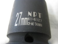
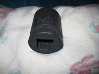
Holding the fan pulley to use the special MB socket to remove the center bolt that goes through the fan clutch.
IMG_8880.jpeg IMG_8886.jpeg IMG_8885.jpeg IMG_8887.jpeg IMG_8888.jpeg IMG_8889.jpeg


Removing the fan......
IMG_8890.jpeg IMG_8891.jpeg IMG_8892.jpeg IMG_8894.jpeg


Here's what things look like with the fan and clutch removed. The second photo shows the grease and dirt caused by the front crankshaft seal leak.
IMG_8895.jpeg IMG_8896.jpeg


I happened to see a small hole caused by a mouse or rat nibbling through one of the sheaths containing the vacuum lines at the front of the engine. This probably happened when I lived in Texas.
IMG_8897.jpeg


Upon removing the radiator, I found that a plastic rivet was missing, that held this piece of rubber trim to the top of the radiator support. So I'll order a couple of new rivets.
IMG_8898.jpeg IMG_8899.jpeg


Removing the tensioner pulley.
IMG_8900.jpeg IMG_8901.jpeg IMG_8902.jpeg


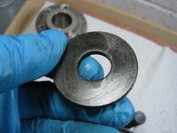
Examining the bearing of the tensioner pulley. If felt a little grainy and rough in its action, so I'm going to look for a new bearing to press into the pulley. A new pulley costs $70 from MB, discounted !!
IMG_8903.jpeg


Removing the three bolts that hold the tensioner to the engine.
IMG_8904.jpeg IMG_8905.jpeg IMG_8906.jpeg IMG_8907.jpeg IMG_8908.jpeg IMG_8909.jpeg IMG_8910.jpeg


Removing the fan pulley.
IMG_8911.jpeg IMG_8912.jpeg IMG_8913.jpeg IMG_8914.jpeg


Removing the coolant overflow reservoir. It is held onto the engine by a bracket with a single 13mm bolt, and another longer bolt that goes down into the block. It has a long hard hose that snakes down around the crank pulley into the top of the reservoir. I removed the lower radiator hose from the water pump, and hosed the reservoir bolt down thoroughly with brake cleaner to expose it and clean it.
IMG_8916.jpeg IMG_8917.jpeg IMG_8915.jpeg


Here are some photos of the reservoir, showing how gummed up with oil that it is from the leaking front crank seal. The second photo is the reservoir, removed from the car.
IMG_8918.jpeg IMG_8919.jpeg


I spent around 1 hour cleaning all of the removed parts, nuts and bolts in my Simple Green Extreme Motorsports cleaner. All of the bolts came out very nicely. They are packaged in sandwich bags and ready for when they are needed at re-assembly time.
 
I won't be able to get it that clean, because the engine is still in the car. But I'm dedicating 10 cans of brake cleaner to do my best to get things cleaned up.

One question -- what is the purpose of that little coolant reservoir that bolts to the front of the block? Is that to catch "weeping" coolant from the water pump or upper radiator hose area?
 
You took your engine out did you not gsxr?
No. That is my wife's E420 DD. Engine didn't come out. More photos here.

With an M119 engine removed, it looks like this.


I won't be able to get it that clean, because the engine is still in the car.
See above... that was with engine in the car. It just requires elbow grease, scrapers, and wire brush along with a case of CRC Red. Really isn't that bad, may an hour or two once all the stuff is removed from the engine.


One question -- what is the purpose of that little coolant reservoir that bolts to the front of the block? Is that to catch "weeping" coolant from the water pump or upper radiator hose area?
Yes. Another example of MB over-engineering. During late 1995 model year production, MB switched to the late-style water pump which eliminated this reservoir completely, for cost reduction. If installing a new reservoir, heat the end to soften it up so it will slip onto the water pump easier. Otherwise it's a PITA as the plastic tube is quite rigid.

:gsxracer:
 
Jackson Auto Machine in Glen Burnie just called, and my manifold set is ready. He hot-tanked it and bead-blasted it and says it cleaned up super nicely. I'll pick it up tomorrow (Wednesday).

In addition to the MB parts I received yesterday, I should be getting another load of parts from MB Annapolis either today or tomorrow. A FedEx box of parts from AutohauZ is coming today, as well.

I'm hoping to put in a few good hours this evening to get the crank seal prepared for replacement. I have to remove the crank bolt after I lock the crankshaft (after removing the crossover pipe for access to the crank lock window), and then I can remove the hub, pulley and vibration dampener so I can get at the seal.

Am SO looking forward to cleaning the front area of the engine up. Will be heading out to the auto parts store while getting my manifolds tomorrow, to get another 6-8 cans of brake cleaner so I can do this job.

The parts I get from MB Annapolis will allow me to begin re-assembling the intake manifold.

Yes. Another example of MB over-engineering. During late 1995 model year production, MB switched to the late-style water pump which eliminated this reservoir completely, for cost reduction. If installing a new reservoir, heat the end to soften it up so it will slip onto the water pump easier. Otherwise it's a PITA as the plastic tube is quite rigid.
What is the purpose for this overflow reservoir? Is it just another coolant repository?
 
I just got off the phone with Don Roden of RFC Electronics, who rebuilt my ETA. It is getting shipped out today and will be in my hands on Thursday or Friday of this week. The cost for the refirb was $379, including shipping.

Remember, my ETA was an original unit from mid-1993 production, and had never been serviced or replaced. I had no issues or running problems with the ETA that precipitated me sending it in -- I just did it as a proactive measure because I was taking the top end of the engine off. I have several spare ETAs in my basement with 2000 or newer wiring, and could have used them, but did not bother because I wanted to re-use my original ETA and keep it on the car.

He said he installed and tested the ETA and drove it on a car, and it is working perfectly.

I asked Mr. Roden about any issues he found with my ETA. He reported that he found the following:
  1. Wiring harness was absolutely toast. Brittle, flaking, and in bad need of replacement. He is including the old harness in the box, but of course installed all new wiring.
  2. Potentiometer was going bad, and was replaced.
  3. DC motor was also bad, and he adjusted it
Note that not all problems with ETAs is just the eco-junk wiring. The ETAs also have other problems with the moving parts and electronics, as mentioned the potentiometers and motors inside. So don't think you can just get away with a re-wire -- there are also going likely to be other issues with them besides the wiring.

In short, I'm very glad that I sent my ETA in, and he was very fast to service it and proactive about calling me with what he found, and to get my payment information after the job was complete. You couldn't talk to a more knowledgeable, nicer and more sincere man.

If you are still on your original ETA, you are very likely living on borrowed time, and should think about getting it serviced (or replacing it with a good used unit).

I will take and post photos of the unit when I recieve it in the mail from Mr. Roden. Can't say enough good things about the experience. Looking forward to putting my intake manifold back together in the coming days, and setting it aside for the re-installation in a few weeks.

Cheers,
Gerry
 
To add in, that reservoir was in case the water pump wept/blew out the weep hole, that it wouldn't spray and short the alternator below it and not just for 'collection' purposes. The only time my car was serviced in that area was for a thermostat they were kind enough to remove the whole assembly and now I have to get another one because the car just can't function properly without it.
 
To add in, that reservoir was in case the water pump wept/blew out the weep hole, that it wouldn't spray and short the alternator below it and not just for 'collection' purposes. The only time my car was serviced in that area was for a thermostat they were kind enough to remove the whole assembly and now I have to get another one because the car just can't function properly without it.

The early m119s had this little overflow box. It was really over engineering at its finest! And MB deleted it in late m119s for cost cutting purposes. Like they way the changed from aluminium oiler tubes to plastic.

Really and truly the engine does not need this little tank and no- it wont dribble and short out anything if not fitted and the water pump leaks.

Having said that - where the car had this little tank fitted I like to re-use it and put it back in place. I did not have to heat these tubes just being gentle and prying on it gets them off in tact.


Jackson Auto Machine in Glen Burnie just called, and my manifold set is ready. He hot-tanked it and bead-blasted it and says it cleaned up super nicely. I'll pick it up tomorrow (Wednesday).

In addition to the MB parts I received yesterday, I should be getting another load of parts from MB Annapolis either today or tomorrow. A FedEx box of parts from AutohauZ is coming today, as well.

I'm hoping to put in a few good hours this evening to get the crank seal prepared for replacement. I have to remove the crank bolt after I lock the crankshaft (after removing the crossover pipe for access to the crank lock window), and then I can remove the hub, pulley and vibration dampener so I can get at the seal.

Am SO looking forward to cleaning the front area of the engine up. Will be heading out to the auto parts store while getting my manifolds tomorrow, to get another 6-8 cans of brake cleaner so I can do this job.

The parts I get from MB Annapolis will allow me to begin re-assembling the intake manifold.

What is the purpose for this overflow reservoir? Is it just another coolant repository?

Hi Gerry, I was actually setting the torque on my m119 crank bolt today. I have a mega sized 3/4 drive Teng torque wrench for this task. And the MB lock tool so I had to remove the crossover pipe as you say.

20200414_152221.jpg 20200414_152538.jpg 20200414_152648.jpg
 
The top end of the pipe flaked off a bit where it pressed on to the water pump. Overall the hose is pretty brittle, so for $40 I just decided to order an entire new reservoir. It comes with the pipe and plastic reservoir together in one unit. It's the GVZ philosophy about proactive replacement of this kind of stuff. I rest easier at night knowing that stuff is proper and appropriate.

I ordered a new 3/4" torque wrench, and it will be arriving next week. So, while I can do the crank seal removal job, I can't finish things up until I get the wrench. Fortunately I already have the socket, which @gsxr confirmed is a 27mm.
 
Yes it is 27mm Gerry and I use a 3/4 27mm socket with this wrench. For fear of an adaptor/ reducer to half inch shearing. (The torque is quite high)

The 3/4 wrench is good to have - I have a small smattering of torque wrenches now

[500Eboard] IMG_2464.JPG.jpg
 
The adapter/reducer that I have is impact rated and high quality, so I have no qualms about using it.

By the way, if you have not replaced your ETA and it is still original ... there's $400 of deferred maintenance (parts only, no labor included) to go toward your $5,000 or $10,000 deferred maintenance total.

I wonder if the ETA has been replaced on the car being offered on BaT by the seller in Texas :texasflag:
 
Yes it is 27mm Gerry and I use a 3/4 27mm socket with this wrench. For fear of an adaptor/ reducer to half inch shearing. (The torque is quite high)

The 3/4 wrench is good to have - I have a small smattering of torque wrenches now

View attachment 101174
Yep, this is my fifth one (the coming 3/4" one). My current largest one only goes up to 200 Nm. I actually have an entire drawer in my tool cabinet dedicated to torque wrenches. Man, that's sick.
 
Tonight I spent about 30 minutes putting together the two top air hoses that go on top of the intake manifold, painstakingly using the diagrams in the Pee-Pee system as a general guide.

After I was done, I went out to the shop and did a comparison between the old and the new hoses. Turns out that I had put together everything correctly, and I then set the assembled hoses aside for the final assembly once the intake manifold is installed. I had purchased these hoses back in late 2018, in one of my first orders from MB Annapolis. I've been saving them for this exact job !!

The hoses were made up of around 25 individual parts, including rubber hoses and plastic connectors. It was sort of like assembling a Lego kit or something.

Here is a comparison of the "new" (left) and "old" (right) air hoses.
IMG_8921.jpeg


A close-up of the new hose on the right, compared with the old hose on the left.
IMG_8922.jpeg


The flexibility of "new" rubber, which you can pretty much bend in half, with "old" rubber, which still has SOME flexibility, but perhaps one-third to one-fourth the flexibility of a new hose. Note that I had replaced these hoses with new MB hoses back in the 2005 time frame, so these "old" hoses are around 15 years old and have around 60-70,000 miles on them. If you have never replaced your air hoses, I can GUARANTEE you they are are hard as rocks and fossilized. These replaced hoses will be good for another 15-20 years.
IMG_8923.jpeg IMG_8924.jpeg


You can bend this new air hose (on the left) in a complete circle and back on itself! The old air hose....not so much.
IMG_8925.jpeg IMG_8926.jpeg


A comparison of the large air hose. The bottom end of this hose goes onto the nipple on the ETA. This is the hose that a lot of folks think is the hardest hose to get at, because you basically can't get at it unless you remove the ETA from the car.
IMG_8927.jpeg IMG_8928.jpeg


The MB hoses have handy arrows that you can use at the junctions to line them up to the correct orientation. Super helpful German engineering !!
IMG_8929.jpegIMG_8930.jpeg

Now that parts are coming in, and my ETA will be returning shortly, it's time to start digging back into the job in a big way. Next up will be more cleaning of the engine and cam solenoid area; the replacement of the front crankshaft seal; the re-assembly of the intake manifold stack; and the installation of the lower wiring harness. These are job components that you will be seeing next.

Cheers,
Gerry
 
The adapter/reducer that I have is impact rated and high quality, so I have no qualms about using it.
You can try using the reducer, but honestly the torque is so big for a 1/2" drive, you may want to consider a 3/4" drive socket to go with your torque wrench w/o any adapter. Even if the adapter will not get sheared, it will stress that square so much, something may get out-of-square or give up. There is a reason why a high torque wrench like this one has a square drive of 3/4" and not 1/2".
The one in the pictures is what I have from Napa: https://www.napaonline.com/en/p/NPT616127?partTypeName=Socket&keywordInput=27mm+socket

My suggestion: Consider getting a 27mm socket with 3 /4" square drive like the one I have for this job while you wait for the torque wrench to show up.
 

Attachments

  • IMG_7085.JPG
    IMG_7085.JPG
    308.2 KB · Views: 22
  • IMG_7087.JPG
    IMG_7087.JPG
    411.9 KB · Views: 24
  • IMG_7088.JPG
    IMG_7088.JPG
    232.6 KB · Views: 27
Last edited:
The early m119s had this little overflow box. It was really over engineering at its finest! And MB deleted it in late m119s for cost cutting purposes. Like they way the changed from aluminium oiler tubes to plastic.

Really and truly the engine does not need this little tank and no- it wont dribble and short out anything if not fitted and the water pump leaks.

Having said that - where the car had this little tank fitted I like to re-use it and put it back in place. I did not have to heat these tubes just being gentle and prying on it gets them off in tact.


Hi Gerry, I was actually setting the torque on my m119 crank bolt today. I have a mega sized 3/4 drive Teng torque wrench for this task. And the MB lock tool so I had to remove the crossover pipe as you say.

View attachment 101166 View attachment 101167 View attachment 101168
I said that the car wouldn't work properly without that tank facetiously. It's been working fine the 7 years it was off. I just have this unnecessary compulsion to just :spend: at the :124:
 
You can try using the reducer, but honestly the torque is so big for a 1/2" drive, you may want to consider a 3/4" drive socket to go with your torque wrench w/o any adapter. Even if the adapter will not get sheared, it will stress that square so much, something may get out-of-square or give up. There is a reason why a high torque wrench like this one has a square drive of 3/4" and not 1/2".
The one in the pictures is what I have from Napa: https://www.napaonline.com/en/p/NPT616127?partTypeName=Socket&keywordInput=27mm+socket

My suggestion: Consider getting a 27mm socket with 3 /4" square drive like the one I have for this job while you wait for the torque wrench to show up.
It's a good thought — thank you Roy! Both my reducer and 27mm socket are impact-rated, so they are stronger than normal. But as you say it may be even better just to go with a 3/4" version of the socket, straightaway. :thumbsup2:


I said that the car wouldn't work properly without that tank facetiously. It's been working fine the 7 years it was off. I just have this unnecessary compulsion to just :spend: at the :124:
It's only $39 for a new tank, and I'm anal about that kind of stuff, so it's on my next parts order and I'll install it on the freshly cleaned front of my engine (when that is done).

Besides, everyone here knows that it would trigger @Jlaa's OCD and keep him up at night if I didn't replace that reservoir on my car.
 
Impact rated or not I would not use any 1/2 drive on that application

:kapow:

Or at least be careful and dont wreck yourself if it does let go
 
Gerry if you were closer (MD better than TX but you’re still far😄) I’d loan you this. I have a paint stick next to it for reference 1587051106926.jpeg
I used it when I did the crank seal when the engine was in last year. You will see a motor twist when that thing is almost to torque. And yes while your attachments are stouter than non impact, the gear attachment can shear off. I’ve had that happen to me more than once, or the pawl inside give out if you're asking it for more than its capacity. I’d even get a cheap 3/4 breaker bar from a truck parts store if you’ve got one close by but then you can’t measure torque.
 
Sorry, not reading up far enough. I see you're getting the torque wrench next week. But maybe a 3/4 breaker bar to take it off. Some people have no problem with it but I don't like to remove things with a torque wrench if it's not set up for reverse/breakaway torque as well.
 
My radiator is out. I will manually remove the crank bolt with a breaker bar, not an impact wrench. I will use the proper torque wrench and an appropriate socket to tighten it down when the time comes. Appreciate all of the suggestions and advice!
 
My first load of factory parts was received from MB Annapolis today. Ordered 4/9/2020; received in hand 4/17/2020. I would have had them earlier this week, but three parts (out of a HUGE order) had to come from Germany, and last Friday was the Easter holiday, so MB Parts was closed for the day. I did not pay shipping, though I did pay Maryland sales tax of 6% on the order. As I said, the price of the parts is 1-3% less expensive than MB Naperville, so realistically everything with tax is around 3-4% higher than I would likely pay at MB Naperville.

A number of parts have supercessions, which I detail below. These were not even reflected in the RevolutionParts catalogs online, or in the ISPPI system.

DescriptionOld Part NumberNew Part NumberPart Notes
HOSE, VACUUM CONNECTOR117 078 01 81117 078 02 81These are the rubber elbows that are found throughout the vacuum system of the E500E engine.
MOLDED HOSE140 476 15 26120 078 01 81These are the rubber elbows that connect the large-diameter black plastic tube to the "MOT" regeneration valve on the driver's side inner fenderwell, next to the EZL.
INTERMEDIATE PIECE INTAKE MANIFOLD UPPER PART TO INTAKE MANIFOLD LOWER PART117 140 02 65117 140 02 65 64These are the eight rubber "donut rings" that mate the top and bottom halves of the intake manifold. This part number supercession means a likely parts supplier change.
PROTECTIVE COVER LEFT, LOWER PART119 158 03 85119 058 06 85Black plastic surround of the cam solenoid and distributor cap, left side.
JAW CLAMP FUEL LINE BRACKET000 995 58 44000 995 58 44 64Indicates a likely supplier change; base part number remains the same.
CLAMP115 995 03 65000 995 66 65Clamp used to hold lines apart. Superseded to a TOTALLY different part, though it looks like new part will be adequate.
LINE014 997 87 82001 997 81 52Vacuum line, 4 x 0.75
CABLE TIE001 997 83 90002 997 24 90 64Cable tie for tying down vacuum lines.
 
For the third from the last item above, where the supercession was to a totally different part, here are illustrations from the Pee-Pee system of the old and the superseded parts:

OLD clamp part:
Screen Shot 2020-04-17 at 4.39.38 PM.jpg


SUPERSEDED clamp part:
Screen Shot 2020-04-17 at 4.41.57 PM.jpg
 
Some of those "pipe separators" are NLA and supercede to different sizes. I went through this drill about 10 years ago. You might be able to use some of what you receive, but some items might not work quite right. I harvest these from junkyard cars now.

:apl:
 
Some of those "pipe separators" are NLA and supercede to different sizes. I went through this drill about 10 years ago. You might be able to use some of what you receive, but some items might not work quite right. I harvest these from junkyard cars now.

:apl:
The problem with that is that junkyard parts (brittle engine compartment plastic clamps) are often in worse shape than the ones i'm replacing !!
 
My refurbished ETA just arrived from Don Roden in Alabama.

65441276-A0B4-4712-AAB4-1A35F91F9470.jpeg F08EF6E4-0A02-4682-B495-45A001C3CF11.jpeg 996140C7-37A5-43D3-A880-C98CB41C49B1.jpeg 8B705976-39D7-4A67-A728-66C1B015DDD7.jpeg 3FD466AB-9ED1-40F4-9B1B-1456C84F46D8.jpeg D271A1C0-95ED-4B05-868F-ABC791735292.jpeg 8103B954-FCF6-4AF3-9D6E-88815B1B2545.jpeg


He included a piece of the exterior harness of the ETA that he replaced with new wiring. Here are some photos of the ends of the wires; I also include a photo of the previously slit-open area (which per my earlier photos had been taped up with electrical tape). Pulling the split apart with my fingers, you can see that the insulation on the wires is TOTALLY gone and flaked off.
64D3EECD-212A-4240-B5CB-828D581AAD0E.jpeg 2B09919F-DFE9-4EA2-8E6E-ABC1068E515B.jpeg 859C6C01-12F3-45B9-8A1E-D5D70A06469C.jpeg A362D950-2C7A-4396-94D0-D34C70BB4391.jpeg

I do not, honestly, know how my ETA (and my car, by extension) was still properly operating.

My advice to you -- if your ETA has not been replaced (if you do not have proof of this) or serviced, it is in dire need of refurbishment or replacement.
 
My refurbished ETA just arrived from Don Roden in Alabama.

View attachment 101337 View attachment 101338 View attachment 101339 View attachment 101340 View attachment 101341 View attachment 101342 View attachment 101344


He included a piece of the exterior harness of the ETA that he replaced with new wiring. Here are some photos of the ends of the wires; I also include a photo of the previously slit-open area (which per my earlier photos had been taped up with electrical tape). Pulling the split apart with my fingers, you can see that the insulation on the wires is TOTALLY gone and flaked off.
View attachment 101343 View attachment 101345 View attachment 101346 View attachment 101347

I do not, honestly, know how my ETA (and my car, by extension) was still properly operating.

My advice to you -- if your ETA has not been replaced (if you do not have proof of this) or serviced, it is in dire need of refurbishment or replacement.
Gerry, was this the original ETA or did you replace this somewhere along the line with a later version? I've heard that later versions can go bad too.
 
Gerry, was this the original ETA or did you replace this somewhere along the line with a later version? I've heard that later versions can go bad too.
This was my original ETA. I had never replaced it, though (per the slit in the cable) I had checked it many years back when I lived in Portland, Oregon. At that time it was fine and did not require replacement. To be honest with you, I did not think the ETA would be NEARLY as bad as it turned out to be.

Later versions of the ETA can definitely go bad, as well. Not from the bio-degradable wiring (which ETAs made after 1998 or so don't have) but from the failure of the internal components (potentiometer, servo motors, gears, etc.) from age and use. That's why it's super important to have someone like Don Roden refurbish them -- because he goes through the entire ETA and repairs everything that requires it -- not just a rewire job.

@jhodg5ck has spoken about this in the past here on the forum -- that he sees a fair number of bad ETAs not because of the wiring, but because the internal components fail.

One thing I should also mention -- Don Roden returns all refurbished ETAs with the factory ETA gasket already attached and ready to install. This means you do not need a gasket (I have 1-2 in my parts stock), and you don't have to go through the process of affixing the gasket before installing it, so that it lines up. The ETA is ready to install on the manifold.
 
Last edited:
Today, now that all of the key parts have come in, I decided to take a break from shop-work out in the garage, and start re-assembling my intake manifold stack. This is a nice task that can be done at one's leisure at the kitchen table, using a couple of layers of beach towel as a protective soft surface for the tabletop.

First, I wiped down the two halves of the intake manifold that I received from the machine shop, to get any residual dust or dirt off of them. They felt slightly powdery to the touch when I picked them up, and sure enough, wiping them down took off a light layer of light-grayish powder. This was probably left-over from the bead-blasting process.

Next, I put a couple of squirts of motor oil into a water-bottle cap, turned upside down, and grabbed a couple of Q-tips from the box that I keep in my garage workbench. This motor oil will come in very handy when re-assembling parts, as you will see shortly. Here's what my motor-oil setup looked like.
IMG_8931.jpeg


Here's the bottom half of the intake manifold, after wiping it down and ready for work.
IMG_8932.jpeg


The first step was to prepare the eight donut rings that mate the two halves of the intake manifold together. These are MB rubber rings, and cost around $6.50 apiece. DO NOT cheap out and buy aftermarket rings -- get the genuine item for this critical part. Take them out of the bag they are received in, and arrange them as you prepare for the next step.
IMG_8933.jpeg IMG_8934.jpeg


Take your Q-tip, and dip it in your cap-ful of motor oil. Then coat the inside sealing surface on the lower half of the donut ring with motor oil. This will help it slide onto the intake manifold lower half easier, and promote better sealing.
IMG_8941.jpeg


Next, slide the ring onto the intake manifold runner, CAREFULLY pushing it down and ensuring that there are no kinks. You want an even seal around the entire ring. Repeat for the next seven rings.
IMG_8939.jpeg IMG_8940.jpeg IMG_8942.jpeg


Here's what all eight rings look like. Now, carefully inspect each ring around its entire circunference by looking at it from the side. You want 100% sealing on these rings.
IMG_8943.jpeg IMG_8944.jpeg


The next thing I did was to install one of the gaskets onto the end of the EGR pipe that will soon be installed onto the lower part of the intake manifold. You can probably get away witih re-using the old gaskets, as they are very thick paper-composite material, but I chose to purchase new ones from MB, as they are pretty cheap. Set the EGR tube aside, for now.
IMG_8945.jpeg IMG_8946.jpeg IMG_8947.jpeg


Next up comes a bit of a PITA -- fitting the crankcase vapor "90-degree" hose onto the ETA. This is a very very tight fit. In the first two photos, I grabbed the newly rebuilt ETA, and remove the black rubber cover that Don Roden had installed onto the nipple where this hose will clamp.
IMG_8948.jpeg IMG_8950.jpeg


At this point, I also replaced a broken plastic MB cable clamp that was atached to the crankcase vapor hose, further up toward the other end from the ETA end of it. I took it out of the package and put it roughly in the same place that the old one was.
IMG_8951.jpeg IMG_8952.jpeg IMG_8953.jpeg


Then it was time to push the crankcase vapor hose onto its nipple on the ETA. I used my trusty Q-tip and gave the inside the hose and the outside of the nipple a light coating of oil, and then with some difficulty (as the clamp was pre-installed) pushed the end of the hose onto the nipple. Then I adjusted the hose to the correct angle, which is a vertical oritentation (pointing straight up). Note that I re-used the old clamp from the mostly fossilized old hose.
IMG_8955.jpeg IMG_8956.jpeg IMG_8957.jpeg


After installing the hose, I laid the ETA into its mounting point in the lower part of the intake manifold, for an initial test-fit. Everything looked good, and I re-checked so that I had the correct orientation for the ETA. The pivot mechanism for the round air intake should be on the driver's side of the intake manifold -- the crankcase vapor hose is located on the front side of the manifold half.
IMG_8958.jpeg


I got my cleaned up ETA bolts from the bag where I'd stored them, and inserted all of them after properly threading them into their holes. The torque setting is 25 Nm to tighten down the ETA bolts to the manifold. Per the factory instructions, you should either put Blue Loctite on the ETA bolts, or replace them with new factory bolts that come pre-Loctited.
IMG_8959.jpeg IMG_8960.jpeg IMG_8961.jpeg IMG_8962.jpeg IMG_8963.jpeg IMG_8964.jpeg


From there, after the ETA was tightened into position, I grabbed the EGR tube, and inserted it into its hole in the manifold. Then I tightened it down using a 5mm Allen socket on a 1/4" ratchet. You don't need to go super tight with these bolts, but make sure they are snugged down well and won't come loose.
IMG_8965.jpeg IMG_8966.jpeg IMG_8967.jpeg IMG_8968.jpeg IMG_8969.jpeg IMG_8970.jpeg IMG_8971.jpeg


Here's what the EGR pipe looks like when snugged down. Note that it is semi-flexible, and its orientation can be changed when the other half of the tube is bolted to the top part of the intake manifold.
IMG_8972.jpeg


Next up, it was time to install the rubber boot that connects the ETA and the MAF. I had this boot in my parts stock since early 2014, and was happy to finally use it. It was a Vaico boot that was sourced from AutohauZ, as you can see in the first three photographs....
IMG_8973.jpeg IMG_8974.jpeg IMG_8975.jpeg


....but this photo shows clearly that the boot is actually an MB boot with the star ground off !!!
IMG_8976.jpeg


Using a small bit of motor oil on the Q-tip, I coated the inside of the MAF boot with a bit of oil to facilitate sliding it onto the top of the ETA. It was slightly resistant at first, but eventually it slid on. I checked carefully to ensure it was well-sealed all the way around (inside and outside) before I tightened the clamp. Note that the boot has a specific orientation, as shown by the two squared off corners in the photo below. These corners are oriented toward the passenger side of the intake manifold.
IMG_8979.jpeg IMG_8980.jpeg IMG_8981.jpeg IMG_8982.jpeg IMG_8984.jpeg


Here are a few photos of the process of tightening the clamp, and what it looks like when fully tightened.
IMG_8988.jpeg IMG_8989.jpeg


Next up, I fit the top clamp, which secures the bottom of the MAF into the boot. It is important that both clamps be accessible from the passenger side of the car, so they should be pointing toward that side for easy access in the future.
IMG_8990.jpeg


Here, I have pressed the MAF into the boot, and am tightening up the clamp. NOTE that the MAF has a notch in the bottom, that directly aligns with a projection in the rubber boot that fits neatly into it. This is how you know that the MAF and boot are in the correct orientation.
IMG_8991.jpeg IMG_8992.jpeg IMG_8993.jpeg IMG_8994.jpeg


And, the finish product ... both clamps tightened. The MAF is in place, and the top part of the intake manifold is almost ready for installation.
IMG_8995.jpeg


But first, let's do one last small job -- let's install the riser for the vacuum tube for the brake booster pipe. This riser is 19mm, so I used my 19mm "stubby" box-end wrench to tighten his riser into the top of the lower intake manifold. Note that there is no washer; there is a flat place in the bottom of the riser above the threads that acts as a washer against the intake manifold.
IMG_8996.jpeg IMG_8998.jpeg IMG_8999.jpeg


And here we are, a fully "loaded" (assembled) lower intake manifold ... ready for marriage with the top half in a very critical operation.
IMG_9000.jpeg
 
Now it's time for the Nuptials — the mating of the top and bottom halves of the intake manifold.

Here you can see the initial preparation for the mating. I gave the top half of each donut ring a light coating of motor oil to help the halves slide into their pockets in the rings.
IMG_9004.jpeg

Then it was time to begin the mating dance. First, I placed the top half on top of the bottom. Then I lined up the donut rings. You can see in the second and third photos below, that everything is almost lined up.
IMG_9002.jpeg IMG_9005.jpeg IMG_9006.jpeg


After lining everything up, press down on the top half of the manifold, and you will feel a "pop" when the runners slide into position in the donut rings. Below shows the rings properly mated. I went around each ring three times, from all angles, with an LED flashlight to ensure that everything was properly sealed at the donut rings.
IMG_9007.jpeg IMG_9008.jpeg


Then it's time to bolt the two halves together. Only four bolts hold the manifold together; they are all 6mm Allen size. The torque as specified by the factory is 25 Nm. I didn't follow this to the letter; I just made sure that everything was snugged down, and quite tight. Note that the rear-most bolts also include eyelet loop plates for engine lifting. These loop plates have holes in them, which fit over small pegs cast into the top half of the intake manifold. I still marked them "driver" and "passenger" when I removed them, so that I know which side was which.
IMG_9009.jpeg IMG_9010.jpeg IMG_9011.jpeg


Tighten everything down, using a criss-cross pattern for evenness.
IMG_9012.jpeg IMG_9013.jpeg IMG_9014.jpeg


There were two outstanding items to do, after the top portion of the manifold was attached: fastening the other end of the metal EGR tube to the top half of the intake manifold; and fastening the vacuum hard pipe to its riser where it comes vertically out of the lower portion of the intake manifold.

First, the EGR pipe. Insert the gasket, line things up, and fasten the two 5mm Allen bolts to hold things in place, as shown below.
IMG_9015.jpeg IMG_9016.jpeg IMG_9017.jpeg IMG_9018.jpeg


Here's what the EGR pipe should look like, properly fastened to the end of the upper intake manifold.
IMG_9019.jpeg


And lastly, the brake vacuum supply pipe. It's a 19mm connector, same as the riser where it screwed into the lower intake manifold. Start it by hand, and then tighten it with a 19mm open-end wrench. I used my "stubby" wrench again, and it worked well. Fasten the top end to the top of the intake manifold using the 10mm bolt, tighten it, and you're mostly do ne with re-assembly of the intake stack.
IMG_9020.jpeg IMG_9021.jpeg IMG_9022.jpeg

The last jobs I need to do are to attach the throttle cable assembly to the rear of the intake manifold, and the spring and cruise control arm to the ETA. These go on the passenger side of the ETA. I'll assemble these in the near future.

Here's what the assembled intake stack looks like, from above.
IMG_9023.jpeg
 
:update:

Late this afternoon I decided to spend a bit of time before dinner in the garage. Total spent working was about 1.5 hours. Here's what I did.

First, I jacked up the car on the driver's side, so that I could get under it. I needed to drop the exhaust crossover pipe so I could get to the crankshaft lock access hole.

After jacking the car up and securing it with a jack-stand, backed up with the raised jack, I got underneath the car and inspected the crossover pipe bolts. They looked decent enough, so I grabbed my 13mm and 12mm box-end wrenches and loosened the bottom connection bolts. They broke loose with not much effort, thankfully.
IMG_9024.jpeg


The upper two bolts (13mm as well) required a socket with a long extension, and for one of the bolts, a "wobbly" to assist with the odd angle. They too loosened without too much effort. All four of the bolts were rusty (as is expected with exhaust hardware), but in decent shape.
IMG_9025.jpeg IMG_9030.jpeg IMG_9031.jpeg IMG_9033.jpeg IMG_9027.jpeg IMG_9028.jpeg IMG_9029.jpeg


After removing the bolts, the crossover pipe was able to be removed from underneath the car without too much difficulty. Before replacing the crossover pipe, I will replace the transmission fluid and drain the torque converter, which also requires the removal of the crossover pipe to do more easily. Here is a photo of the crossover pipe.
IMG_9034.jpeg


Next up, with the crossover pipe removed, the crank lock cover is exposed. This is a sheet metal panel that is held to the transmission by two 5mm Allen bolts. I removed these (after cleaning them out and shooting the area with some brake cleaner) and removed the panel from the car.
IMG_9035.jpeg IMG_9036.jpeg IMG_9037.jpeg


I pulled out the crank lock tool, which I had purchased a couple of years ago in anticipating of doing this job. This crank lock also works for the M117 engine.
IMG_9038.jpeg IMG_9039.jpeg


Here is what the flywheel looks like, with the crank lock cover removed.
IMG_9040.jpeg IMG_9041.jpeg


I inserted the crank lock into the two large holes. It did not quite mesh with the flywheel, as it was not properly lined up. I attached a 27mm socket to the crank bolt, and rotated the engine about 1/2 of a centimeter. Getting back under the car, I was able to mesh the crank lock with the flywheel after rotating the engine. Then I took a small hammer and tapped the crank lock all of the way into the transmission housing. You can see it fully inserted, in the photo below. The engine's crankshaft is effectively locked, and cannot move when this tool is inserted.
IMG_9042.jpeg


A couple of photos of the crank lock inserted. You can't quite see the teeth meshed with the flywheel's teeth, despite my best attempts at trying to get a photo of such.
IMG_9043.jpeg IMG_9046.jpeg IMG_9048.jpeg


While under the car, looking around, I noticed an apparent oil leak at the transmission overload protection switch. Looks like I'll need to order one of these and replace this switch.
IMG_9047.jpeg


With the crank LOCKED, I could turn to the crux of the task at hand -- loosening the torqued-on crankshaft bolt. This bolt's torque spec is 400 Nm (around 300 ft-lbs) -- probably the tightest bolt on the entire car.

I was able to loosen it with a 27mm "impact" rated socket, mated to a 1/2" socket. I used the handle from my floor jack, turned upside down, as a "lever" to loosen the bolt. In the first photo below you can see this handle and the loosening process. Once it broke free, I was able to use my hand and the socket to loosen and then remove the crankshaft bolt.
IMG_9049.jpeg IMG_9050.jpeg IMG_9051.jpeg IMG_9052.jpeg


Here is what the crankshaft bolt and four concave washers look like, after removal.
IMG_9053.jpeg


My Yellow Lab, Chase, sighed a big sigh of relief with me as I removed the crank bolt from the car.
IMG_9055.jpeg


After removing the crank bolt, I removed the six 13mm bolts that hold the crank pulley to the crankshaft hub. Of course, I marked everything and took photos to ensure that it will be properly aligned upon reassembly.
IMG_9057.jpeg IMG_9058.jpeg


Removal of the crank pulley off of the hub. Look at the dirt that was in the pulley! Note that this was probably about half the dirt that was originally on there -- the rest of it had already fallen off. Looks like a lot of Texas sand....
IMG_9059.jpeg IMG_9060.jpeg IMG_9061.jpeg IMG_9062.jpeg


Markings I made on the crank pulley and harmonic balancer to line them up properly on reassembly. I cleaned the pulley and bolts, and re-marked everything once I cleaned it.
IMG_9063.jpeg IMG_9064.jpeg IMG_9066.jpeg


My last step for the night was to begin attaching the "puller" to remove the combined harmonic balancer, and the hub, from the end of the crankshaft. This puller fits in three of the six holes in the crankshaft hub. The size of the puller bolts is M8. I stopped at this point, and did not continue further. I'll pick this job up in the next update.
IMG_9067.jpeg IMG_9068.jpeg
 
Nice update honch. Did not know you needed a puller for the balancer on the m119, i would thought( (no I haven’t read the FSM) it was the same process.
 
When time comes to put the crankshaft bolt back, before assembly smear with an extremely fine film of grease the spring washers on both sides. The reason is that as you will tighten the bolt, those spring washers will deform from their conical shape to almost flat. In that process a very small amount of lubricant will decrease the friction between the washer surfaces and allow the washers to "settle" from the beginning rather than later.

I exaggerated the amount of grease in the picture for exemplification purposes only, but the amount of grease should be barely visible (only enough to repel water, not more). If it looks like my picture, then is already too much.
 

Attachments

  • IMG_6791.JPG
    IMG_6791.JPG
    451.9 KB · Views: 29
That is correct, Roy. The FSM says to “oil” both the bolt threads and the washers before installation. It’s going to be interesting to see what 400Nm of torque feels like.

I felt that the impact-rated deep socket with the 1/2” ratchet and the breaker bar held up just fine, strength-wise. The factory service manual does specify a 3/4” to 1/2” “reducer” for the crank bolt socket, FYI. My new 3/4” torque wrench arrived on Saturday.

@281lxm, the harmonic balancer can be removed from the hub separately, but also per the factory service manual as a unit with the hub. I’m fine with removing them together as I can mark them together, as I marked the position of the belt pulley relative to the harmonic balancer. The FSM says to mark everything.

I also have to mark the hub position relative to the crank snout (FSM specifies a chisel), but if I understand things correctly the hub can only go on the crank one way, in one proper position, once heated, due to the Woodruff key that fits on the crank into a slot in the hub.
 
You can try using the reducer, but honestly the torque is so big for a 1/2" drive, you may want to consider a 3/4" drive socket to go with your torque wrench w/o any adapter. Even if the adapter will not get sheared, it will stress that square so much, something may get out-of-square or give up. There is a reason why a high torque wrench like this one has a square drive of 3/4" and not 1/2".
The one in the pictures is what I have from Napa: https://www.napaonline.com/en/p/NPT616127?partTypeName=Socket&keywordInput=27mm+socket

My suggestion: Consider getting a 27mm socket with 3 /4" square drive like the one I have for this job while you wait for the torque wrench to show up.
Impact rated or not I would not use any 1/2 drive on that application

Or at least be careful and dont wreck yourself if it does let go
As an FYI:

I just wanted to follow up and I do note that the factory service manual does mention the 3/4" to 1/2" reducer for the crank bolt socket.

See it in the attached procedure.

Screen Shot 2020-04-20 at 6.57.13 AM.jpg

This is the adapter mentioned: Hazet 1058-2 Adapter, 3/4" drive to 1/2" drive, 52.3mmDefault Title
 

Attachments

Well that's good then. Now we know it can be done. I just remember shearing off a 1/2" breaker bar connector once because the torque was so high (truck lug nut) and thought I would never want to do that again if possible. But glad that not only you could do it but it's also done in the workshop manual.
Also, when I disassembled my manifold, there was a sealing ring between the booster pipe and the manifold itself. 14x18x1.5 measurement (same size as the switch sealing rings on the manifold). This manifold was untouched from the factory so it's maybe odd that yours didn't have one and mine did (94 E420 btw)? I'll be putting one back in on install as that's how I found it. The funny thing is that it doesn't show up as needing it on the EPC also.
 
Thank you, Gerry. I was aware of that note (the M117 FRM section has it too). I would only like to stress that the FRM mentions a tool made by a reputable tool maker that also happens to be more than 2x the tool I mentioned earlier (which I already used it 3 times w/o any problems).

I guess when it comes to this job, our members will be able to make an informed decision as to which tool to buy. Having something to chose from is always a good "problem" to have. :)
 
I think that the 1/2 is prone to a 24” bar or ratchet but like GVZ used the 4’ pipe extender the physics made it less of a sheer failure by transferring up the lever. Quality tools wear out too, metal fatigue happens.
 
Last edited:
For the record, I have a 3/4" breaker bar and socket, and use an extension pipe on these as needed... mostly for 1995-up models which need the 90° rotation. When you start getting to this level of force, 1/2" drive tools are nearing their limits, and cheaper ones may fail spectacularly.

FSM shows the direction of the Belleville washers and specifies clean engine oil; I use non-synthetic 30W for this application. 400Nm is a lot, which is why 3/4" torque wrenches have such long handles - you need every bit of that leverage!

:duck:
 
One item that I ordered, and just received, will be important for the final assembly of the wiring and vacuum lines routed in the engine bay. Over the years, I have found that the corrugated black plastic sheathing for the vacuum lines and such has disintegrated and splintered and just disappeared ... crumbling into dust. There was very very little of it left when I started taking things apart on this top-end job.

What I did, in addition to ordering all new vacuum lines and connectors for everything in the engine bay, was to get new, heat resistant sheathing for the lines. I ordered this stuff on Amazon, and just received it. I ordered both 1/2" and 1/4" sizes.

It is called "Hot Rod Sleeve" from Heatshield Products, in Southern California. Made in the USA. The packaging says that it is designed to withstand 1100F temperatures.

I think this is a better solution than again using the cheap, corrugated sheathing (or the split stuff that you can get at your local FLAPs store). When I install this stuff, I'll attach some photos. This, of course, won't be until the final assembly stages.

4BB6C1A7-7BA2-4B89-9AB3-302118E6F236.jpeg
 
Tonight I removed the crankshaft "hub" and harmonic balancer from the crankshaft. I used the puller I had, and a 3/4" box-end wrench to pull it off. It wasn't too much effort, but took a bit of strength. This exposed the leaking crankshaft seal, and the dirty area around the crank on the front of the timing cover and the top of the oilpan.

After installing the puller, I began turning the center shaft of the puller in a clockwise direction. This began the "pulling" action or the harmonic balancer and hub, together.
IMG_9070.jpeg


In the next couple of photos, you can see the hub and balancer progressively being pulled off of the crankshaft snout.
IMG_9071.jpeg IMG_9072.jpeg


Here, the puller has been removed from the hub, and the hub has been extracted all of the way off of the crank snout. It can be removed by hand from here out. Note the black mark (made with a Sharpie marker) and the mark on the front of the block, to line up the hub and the crank (which has a Woodruff key on it for aligning the hub. Pull the hub off of the crank when it gets to this point.
IMG_9074.jpeg IMG_9075.jpeg


With the hub removed from the crankshaft, I clamped it in a bench vise, and made a mark with a center punch where the Sharpie mark had been made with the hub on the car. Here you can see the center punch being used, and the small mark it made on the edge of the hub.
IMG_9076.jpeg IMG_9077.jpeg


And here on the block, I made a corresponding mark with the center punch to formalize this marking I'd made earlier with a screwdriver. This will help when aligning the hub (with the Woodruff key) after installing the new front crank seal.
IMG_9078.jpeg IMG_9079.jpeg


The next step is to thoroughly clean the area (I will block off the crank snout with tape to avoid dirt getting inside the engine past the seal). Then I will replace the seal, and re-install the hub, harmonic balancer and pulley. Note the pieces of corrugated wire and vacuum line sheathing that have flaked off over the years, and were sitting on top of the oil pan. These are also being removed. Hopefully the next installment will show "before" and "after" photos of the front of the timing cover being cleaned. I have 15 cans of brake cleaner ready to go to assist with cleaning!!
IMG_9080.jpegIMG_9081.jpeg


Here are a few close-up views of the hub. You can clearly see the shiny area on the hub where the old crank seal rested. Although I couldn't "snag" this shiny area with my fingernail, I could definitely feel with my fingertips that the area was worn and slightly depressed from the rest of the hub surface.
509880ED-5CE6-4553-8695-FF2B492BF346.jpeg A555EE2E-A7A3-47FF-8759-3625446B15BD.jpeg


Here's what the seal look like next to the hub, and resting on the hub in roughly the same position as the original seal. The trick will be to "set" the new seal in the end of the timing cover in a position where it is 2-3 mm off-set from the "old" crank seal position, which is where the shiny/depressed area is on the hub.
8138173A-F43F-4AF5-AA83-7360B1F370AC.jpeg 2F5CC657-142E-4A46-BBD3-60EB38A44CBF.jpeg


Here are a couple of close-up views of the hub, where you can really see the crank seal's resting area on the hub.
DA86089E-8C3C-442D-B059-54E7B694C6FB.jpeg EA011383-F607-4403-93A8-012B1CBAABE3.jpeg
 
Gerry, before you remove the old seal, try to gauge how far inward it is seated. Press the tool in by hand (with the OLD seal still in place) and see if the tool pushes up against the face of the timing cover. If so, the seal should be inset 3mm already - meaning it was replaced previously.

If you find the seal is only inset 1.0-1.5mm, it is likely original from the factory. You then have a choice of either setting it in 3mm, or having it sit proud of the timing cover ~1mm or so. I chose the latter option as you can see in my photos linked to previously.

Whatever you do, try to get the new seal set at LEAST 2mm away from where the original was. Also, clean up the hub surface with ScotchBrite or similar. If you can catch a fingernail on the groove in the hub... that isn't good.
 
Back
Top