Navigation
Install the app
How to install the app on iOS
Follow along with the video below to see how to install our site as a web app on your home screen.
Note: This feature may not be available in some browsers.
More options
Style variation
-
Hi Guest !
Welcome to the 500Eboard forum.
Since its founding in late 2008, 500Eboard has become the leading resource on the Internet for all things related to the Mercedes-Benz 500E and E500. In recent years, we have also expanded to include the 400E and E420 models, which are directly related to the 500E/E500.
We invite you to browse and take advantage of the information and resources here on the site. If you find helpful information, please register for full membership, and you'll find even more resources available. Feel free to ask questions, and make liberal use of the "Search" function to find answers.
We hope you will become an active contributor to the community!
Sincerely,
500Eboard Management
You are using an out of date browser. It may not display this or other websites correctly.
You should upgrade or use an alternative browser.
You should upgrade or use an alternative browser.
RESTO PROJECT: M119 / W124 / E500 Engine Top-End Refresh
Today, I spent about 3.5 hours total out in the shop, taking my time and getting a few things completed.
The first item for the day was to re-install the tandem pump + bracket onto the front of the engine. Since (per my post this morning) it's only held to the engine by three bolts, and TWO of the three bolts are accessible from the front of the engine, I installed it with these two upper-most bolts. I will have to get under the car to get the third bolt tightened.
Here are a couple of photos, readying, and then lifting the tandem pump + bracket into the engine compartment, and lowering it into place.

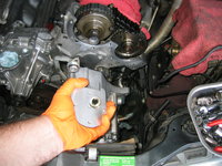

Temporarily inserting the 6mm Allen bolt to mount one side of the bracket....
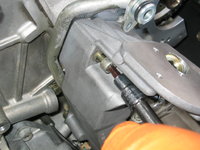
Here's the other side of the bracket, at the lower corner of the driver's side cylinder head. The 13mm bolt pokes through from the BACK side (the end is peeking out in the second photo, for illustrative purposes). It's tightened from behind, and in the third photo everything is snugged down into the corner of the bracket.


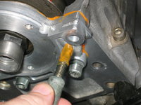
Here I'm removing the 6mm bolt, so I can apply the orange koala-claw goo (anaerobic sealant), to the end of the bolt, as it pokes through the outside casting and into the timing chain area. I decided to use my old koala-claw goo, as it still seemed fine enough to use, and I had plenty left for the job. A Q-tip helped spread the goo onto the threads of the bolt.


Inserting and tightening the bolt again. This will prevent oil leaks through the bolt's threads.


With the pump and bracket mounted, I put a piece of lint-free paper towel back into the short-hose, to prevent any dirt from entering the power steering pump.

Next, it was time to test-fit the passenger-side (right) cylinder head front cover. Everything had been cleaned many moons ago, so it was basically ready to roll. Mainly, I wanted to see how the new Elring cam seal would fit over the end of the exhaust cam. Of course, the distributor and its insulator will be going over this in the future. It can be a bit of a tight fit (as it should be) to get the seal properly OVER the end of the cam, to ensure a good seal. As you can see, it went into place nicely with a minimum of fuss.
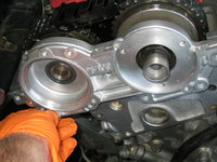

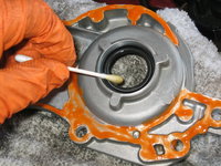
The next step was to put the anaerobic koala-claw orange goo onto the sealing surface on the back-side of the front cover. I spread a medium-thick coating of goo on the sealing surfaces, as you can see in the fourth photo. I realized that I had slightly erred, and did not need to apply the orange sealant on the upper (curved) surface of the front cover, so I wiped it off after realizing my mistake. I also took a Q-tip and spread a very light layer of ordinary motor oil onto the inside of the Elring cam seal, to assist it in sliding over the end of the cam. This is a small step, but it helps a lot.


This is what the cylinder head front cover looks like, once installed and pressed into place. The second photo shows a close-up of the cam seal -- again, all looks good.


From there, you need to install the seven 6mm Allen bolts that hold the cover to the head. On the right (passenger) side, the bolt with the long sholder is the inner-most and upper-most bolt -- closest to the "Vee" of the engine. The last couple of centimeters of each bolt's threads MUST be coated with a good coat of orange koala-claw sealant, as they penetrate the timing chain area, and you don't want the bolts leaking oil through their threads.


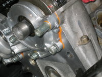
Tighten each bolt down to its specified torque of 21 Nm (15.5 lb-ft). You should have a nice even layer of orange goo squeezing out from the edge of the front head cover. You can wipe this up if you want to, or you can leave it. I will probably leave it, but as it won't dry (as it is exposed to the air), I can always go back and wipe it up if I care to. Here are a couple of photos of the torqued-down head cover on the right side.

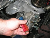
After doing that, I took a stubby flat-blade screwdriver, while I happened to think about it, and cinched down each of the two hose clamps for the power steering "short hose" by about 1/4 turn, to make sure they are nice and tight.
For the left (driver's) side, you basically just repeat the same process that you did for installing the cylinder head front cover on the right (passenger) side. You can see the steps .... installing the orange goo on the sealing surface, lightly oiling the new Elring cam seal, and then carefully installing and pressing the cover into place.


When it comes time to tighten the bolts, however, there is ONE difference that the driver's side has over the passenger side. Note that on the right of the line of bolts in the first photo below, one bolt is longer than the others. This longer bolt goes directly BELOW the long-headed bolt (which like the passenger side, goes in the uppermost and inner position nearest the engine's "Vee." This longer-threaded bolt goes in the position directly BELOW this bolt. As before, you MUST put a good coating of orange goo on the threads of the end of each bolt.
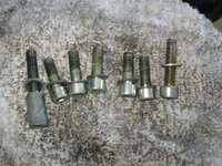

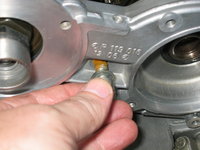
Here is a comparison of the longer-threaded bolt, compared to a regular cylinder head cover bolt. The second photo shows the insertion of the longer-threaded bolt below the long-headed bolt.

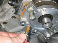
Torque each bolt down to its specified 21 Nm. I like to do a criss-cross pattern, working inward and alternating from the ends.

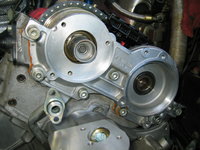
And voila! Here is what the installed and torqued left-side cylinder head cover looks like, along with a close-up of the cam seal. All looks good and came together pretty easily.

The last task I started for the day was to re-install the two 13mm bolts that hold the tandem pump to its mounting bracket. Both of these are easily accessible from the front of the engine. I probably should have installed them when I installed the rear 6mm Allen mounting bolts yesterday, but I didn't think of it, so I just took care of it now.

Now that the front cylinder head covers are installed, I can install the red powder-coated valve covers, and I look forward to doing that. I will give each cam lobe and the timing chain a shot of assembly lube, because they have been exposed to air for a couple of months. The sticky assembly lube will help assure that the cams don't wear from lack of lubrication when I crank the engine to build up oil pressure, at the conclusion of this job.
Thanks for your interest!
Cheers,
Gerry
The first item for the day was to re-install the tandem pump + bracket onto the front of the engine. Since (per my post this morning) it's only held to the engine by three bolts, and TWO of the three bolts are accessible from the front of the engine, I installed it with these two upper-most bolts. I will have to get under the car to get the third bolt tightened.
Here are a couple of photos, readying, and then lifting the tandem pump + bracket into the engine compartment, and lowering it into place.


Temporarily inserting the 6mm Allen bolt to mount one side of the bracket....

Here's the other side of the bracket, at the lower corner of the driver's side cylinder head. The 13mm bolt pokes through from the BACK side (the end is peeking out in the second photo, for illustrative purposes). It's tightened from behind, and in the third photo everything is snugged down into the corner of the bracket.


Here I'm removing the 6mm bolt, so I can apply the orange koala-claw goo (anaerobic sealant), to the end of the bolt, as it pokes through the outside casting and into the timing chain area. I decided to use my old koala-claw goo, as it still seemed fine enough to use, and I had plenty left for the job. A Q-tip helped spread the goo onto the threads of the bolt.


Inserting and tightening the bolt again. This will prevent oil leaks through the bolt's threads.


With the pump and bracket mounted, I put a piece of lint-free paper towel back into the short-hose, to prevent any dirt from entering the power steering pump.

Next, it was time to test-fit the passenger-side (right) cylinder head front cover. Everything had been cleaned many moons ago, so it was basically ready to roll. Mainly, I wanted to see how the new Elring cam seal would fit over the end of the exhaust cam. Of course, the distributor and its insulator will be going over this in the future. It can be a bit of a tight fit (as it should be) to get the seal properly OVER the end of the cam, to ensure a good seal. As you can see, it went into place nicely with a minimum of fuss.


The next step was to put the anaerobic koala-claw orange goo onto the sealing surface on the back-side of the front cover. I spread a medium-thick coating of goo on the sealing surfaces, as you can see in the fourth photo. I realized that I had slightly erred, and did not need to apply the orange sealant on the upper (curved) surface of the front cover, so I wiped it off after realizing my mistake. I also took a Q-tip and spread a very light layer of ordinary motor oil onto the inside of the Elring cam seal, to assist it in sliding over the end of the cam. This is a small step, but it helps a lot.


This is what the cylinder head front cover looks like, once installed and pressed into place. The second photo shows a close-up of the cam seal -- again, all looks good.


From there, you need to install the seven 6mm Allen bolts that hold the cover to the head. On the right (passenger) side, the bolt with the long sholder is the inner-most and upper-most bolt -- closest to the "Vee" of the engine. The last couple of centimeters of each bolt's threads MUST be coated with a good coat of orange koala-claw sealant, as they penetrate the timing chain area, and you don't want the bolts leaking oil through their threads.


Tighten each bolt down to its specified torque of 21 Nm (15.5 lb-ft). You should have a nice even layer of orange goo squeezing out from the edge of the front head cover. You can wipe this up if you want to, or you can leave it. I will probably leave it, but as it won't dry (as it is exposed to the air), I can always go back and wipe it up if I care to. Here are a couple of photos of the torqued-down head cover on the right side.


After doing that, I took a stubby flat-blade screwdriver, while I happened to think about it, and cinched down each of the two hose clamps for the power steering "short hose" by about 1/4 turn, to make sure they are nice and tight.

For the left (driver's) side, you basically just repeat the same process that you did for installing the cylinder head front cover on the right (passenger) side. You can see the steps .... installing the orange goo on the sealing surface, lightly oiling the new Elring cam seal, and then carefully installing and pressing the cover into place.


When it comes time to tighten the bolts, however, there is ONE difference that the driver's side has over the passenger side. Note that on the right of the line of bolts in the first photo below, one bolt is longer than the others. This longer bolt goes directly BELOW the long-headed bolt (which like the passenger side, goes in the uppermost and inner position nearest the engine's "Vee." This longer-threaded bolt goes in the position directly BELOW this bolt. As before, you MUST put a good coating of orange goo on the threads of the end of each bolt.


Here is a comparison of the longer-threaded bolt, compared to a regular cylinder head cover bolt. The second photo shows the insertion of the longer-threaded bolt below the long-headed bolt.


Torque each bolt down to its specified 21 Nm. I like to do a criss-cross pattern, working inward and alternating from the ends.

And voila! Here is what the installed and torqued left-side cylinder head cover looks like, along with a close-up of the cam seal. All looks good and came together pretty easily.


The last task I started for the day was to re-install the two 13mm bolts that hold the tandem pump to its mounting bracket. Both of these are easily accessible from the front of the engine. I probably should have installed them when I installed the rear 6mm Allen mounting bolts yesterday, but I didn't think of it, so I just took care of it now.

Now that the front cylinder head covers are installed, I can install the red powder-coated valve covers, and I look forward to doing that. I will give each cam lobe and the timing chain a shot of assembly lube, because they have been exposed to air for a couple of months. The sticky assembly lube will help assure that the cams don't wear from lack of lubrication when I crank the engine to build up oil pressure, at the conclusion of this job.
Thanks for your interest!
Cheers,
Gerry
Due to other things I had to do, I was only able to spend about an hour out in the shop on Sunday. But it was one heck of a fun hour!!
Here's what I did during that time.
First, closing up the job from Saturday, here is a view of the two front tandem-pump mounting bolts, all snugged down.

I only have the remaining one tandem pump mounting bracket bolt to replace from underneath the car, as well as the following items: "S" power steering hose; ground to bottom of mounting bracket; and the driver's side motor mount cooling pipe. Then I can replace the wheel well cladding on both sides, as I've completed all of the work on the fog lamps. Lastly, I'll replace the flywheel lock under the car, so I can lower the car, install the front crankshaft pulley, and torque the crankshaft bolt down to its' specified 400 Nm.
But in the mean-time, it was time to have a bit of fun in the garage! It was time to begin putting the valve covers back on. First, I took a stout rag, with the corner soaked in brake cleaner, and made a few passes along the sealing surface on the top-edge of the cylinder head. This is the surface where the valve cover gasket lies. The photos below show the sealing surfaces "dirty" and in the process of "being cleaned".


The last step before putting the valve cover into place, was to add a little assembly lube to the camshaft lobes. Ordinarily, with a "regular" job where the valve covers were off the car for a few hours, or a few days, I wouldn't bother with this step. But, seeing as the valve coves have been off the car since April, I decided to add a bead of assembly lube to the lobes, to reduce metal-on-metal wear when I start up the car in the future. These lobes have been exposed to air and to my shop rag covers (which absorb any light coating of oil on the lobe surfaces). It's basically just cheap insurance against any cam problems.


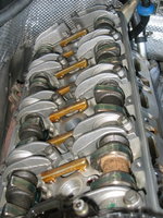
Next, I ran my fingers around the valve cover seal, to make sure it was properly seated all the way around the cover. It was a bit loose in a couple of places, so I smoothed it down. Then I lowered the valve cover into position atop the cylinder head. It's important to make sure the back-side of the cover clears everything, like the heater hose and the lower wiring harness, without dislodging the valve cover seal accidentally. The third photo shows the valve cover in position.


The next thing to do was to prepare the nine bolts that hold the cam cover to the cylinder head. A couple of notes for this step: 1) new copper washers are required for the bolts (a total of 18 washers for the car); and 2) one of the bolts is longer than the other eight, and this "long" bolt goes on the upper and front-most hole in the valve cover. Get your washers out and insert a washer on each bolt. Then carefully put each bolt+washer in the holes, as shown in the fourth photo below.


Another note for M119.97x owners: Early versions of the 119.97x engine used THREE different sizes of valve cover bolts, while later versions only used the two sizes shown. The factory service manual shows the installation position of the valve cover bolts for both versions. It's important to follow this diagram in the FSM carefully, so that the correct bolts are located in the correct locations. My car, an early 1994 model, has the "two sizes of bolt" version.
The bottom and rear-most bolt requires some doing, because of the difficult angle due to the inner firewall and a lack of clearance. This is the bolt that requires the "swivel" 5mm socket to remove. I used a magnetic pickup to carefully insert the bolt and washer into the hole. The washer falls off easily, so you may want to use some adhesive (rubber or contact cement would work well) to lightly tack it to the bolt before you insert it down into position.

Tightening the bolts is straightforward. As mentioned, two of the nine bolts on the right (passenger) side require the special "swivel" 5mm socket to tighten -- the rear lower corner bolt (inserted in the previous photo), and the front lower corner bolt, which is partially obstructed with the SLS fluid reservoir. You can see here that in addition to the swivel socket, I also used a "curved" flexible shaft attached to the ratchet for additional clearance from the SLS reservoir.
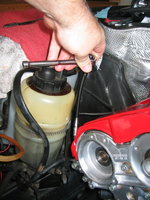
And this is what the valve cover looks like, snugged into place. The tightening torque for all valve cover bolts is only 9Nm. It is advisable to re-torque the valve cover bolts a few days or a week after initial tightening, to be sure that everything is up to spec.
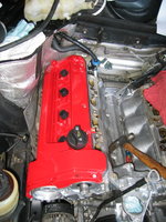
The red bling looks good, eh? On to the second valve cover next, and then re-installing the smog pump.
Thanks for your interest,
Cheers,
Gerry
Here's what I did during that time.
First, closing up the job from Saturday, here is a view of the two front tandem-pump mounting bolts, all snugged down.

I only have the remaining one tandem pump mounting bracket bolt to replace from underneath the car, as well as the following items: "S" power steering hose; ground to bottom of mounting bracket; and the driver's side motor mount cooling pipe. Then I can replace the wheel well cladding on both sides, as I've completed all of the work on the fog lamps. Lastly, I'll replace the flywheel lock under the car, so I can lower the car, install the front crankshaft pulley, and torque the crankshaft bolt down to its' specified 400 Nm.
But in the mean-time, it was time to have a bit of fun in the garage! It was time to begin putting the valve covers back on. First, I took a stout rag, with the corner soaked in brake cleaner, and made a few passes along the sealing surface on the top-edge of the cylinder head. This is the surface where the valve cover gasket lies. The photos below show the sealing surfaces "dirty" and in the process of "being cleaned".


The last step before putting the valve cover into place, was to add a little assembly lube to the camshaft lobes. Ordinarily, with a "regular" job where the valve covers were off the car for a few hours, or a few days, I wouldn't bother with this step. But, seeing as the valve coves have been off the car since April, I decided to add a bead of assembly lube to the lobes, to reduce metal-on-metal wear when I start up the car in the future. These lobes have been exposed to air and to my shop rag covers (which absorb any light coating of oil on the lobe surfaces). It's basically just cheap insurance against any cam problems.


Next, I ran my fingers around the valve cover seal, to make sure it was properly seated all the way around the cover. It was a bit loose in a couple of places, so I smoothed it down. Then I lowered the valve cover into position atop the cylinder head. It's important to make sure the back-side of the cover clears everything, like the heater hose and the lower wiring harness, without dislodging the valve cover seal accidentally. The third photo shows the valve cover in position.


The next thing to do was to prepare the nine bolts that hold the cam cover to the cylinder head. A couple of notes for this step: 1) new copper washers are required for the bolts (a total of 18 washers for the car); and 2) one of the bolts is longer than the other eight, and this "long" bolt goes on the upper and front-most hole in the valve cover. Get your washers out and insert a washer on each bolt. Then carefully put each bolt+washer in the holes, as shown in the fourth photo below.


Another note for M119.97x owners: Early versions of the 119.97x engine used THREE different sizes of valve cover bolts, while later versions only used the two sizes shown. The factory service manual shows the installation position of the valve cover bolts for both versions. It's important to follow this diagram in the FSM carefully, so that the correct bolts are located in the correct locations. My car, an early 1994 model, has the "two sizes of bolt" version.
The bottom and rear-most bolt requires some doing, because of the difficult angle due to the inner firewall and a lack of clearance. This is the bolt that requires the "swivel" 5mm socket to remove. I used a magnetic pickup to carefully insert the bolt and washer into the hole. The washer falls off easily, so you may want to use some adhesive (rubber or contact cement would work well) to lightly tack it to the bolt before you insert it down into position.

Tightening the bolts is straightforward. As mentioned, two of the nine bolts on the right (passenger) side require the special "swivel" 5mm socket to tighten -- the rear lower corner bolt (inserted in the previous photo), and the front lower corner bolt, which is partially obstructed with the SLS fluid reservoir. You can see here that in addition to the swivel socket, I also used a "curved" flexible shaft attached to the ratchet for additional clearance from the SLS reservoir.

And this is what the valve cover looks like, snugged into place. The tightening torque for all valve cover bolts is only 9Nm. It is advisable to re-torque the valve cover bolts a few days or a week after initial tightening, to be sure that everything is up to spec.

The red bling looks good, eh? On to the second valve cover next, and then re-installing the smog pump.
Thanks for your interest,
Cheers,
Gerry
About 30 minutes this afternoon, spent out in the shop. putting the other valve cover onto the car.''
Exposing the slumbering cylinder head from its cover of shop-rags.

Applying some assembly lube onto the camshaft lobes and timing chain.

...And lowering the valve cover into position, and securing it down.


Preparing the nine bolts (again, with one long one on the upper front inside position), with new copper washers.

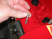
Placing the difficult lower rear bolt and washer into position, with a magnetic pickup tool.

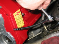
Snugging each bolt down with a flexible shaft, before torquing each bolt to its 9Nm torque.

Final torquing...

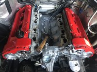
And the final view with both covers installed. I like it.
Exposing the slumbering cylinder head from its cover of shop-rags.

Applying some assembly lube onto the camshaft lobes and timing chain.

...And lowering the valve cover into position, and securing it down.


Preparing the nine bolts (again, with one long one on the upper front inside position), with new copper washers.


Placing the difficult lower rear bolt and washer into position, with a magnetic pickup tool.

Snugging each bolt down with a flexible shaft, before torquing each bolt to its 9Nm torque.


Final torquing...

And the final view with both covers installed. I like it.

Quick 30 minutes out in the shop, after I answered my morning work e-mail (and @JC220's hammer poke).
Re-attached the smog pump, and fit it into position.
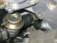
To attach the pump to the engine, there are three 13mm bolts. Before attaching the bolts, slide the smog pump valve fitting into the end of the rubber hose, as shown in the first photo. After you start sliding it into position, take a pair of pliers (channel-locks work decently for this) and compress the spring clamp, and slide it into position. Holding the clamp open slightly with the pliers, finish pushing/working the hose the rest of the way onto the valve's fitting. Then release the pliers, as you've got it !!


The next step is to coat the ends of the three 13mm smog pump bolts with the orange anaerobic sealant. For neatness purposes, insert all three bolts into their respective holes (the longer of the bolts goes into the lower left hole), and coat the ends with the orange goo. Then insert them into the cylinder head, and tighten to their specified torque of 25 Nm.


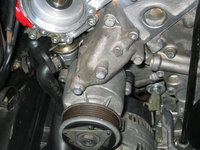
This is what the smog pump looks like, when properly mounted. The second photo shows a close-up of the valve, with the new hoses attached. I can GUARANTEE you that if you have not ever replaced these hoses (and who has?), they are now made of petrified rubber. As shown earlier in the HOW-TO, all of the smog pump hoses are relatively cheap.

After installing the smog pump, don't forget to plug it in at its electrical connection behind and under the passenger-side headlight.
Cheers for your interest in this brief installment,
Gerry
Re-attached the smog pump, and fit it into position.
To attach the pump to the engine, there are three 13mm bolts. Before attaching the bolts, slide the smog pump valve fitting into the end of the rubber hose, as shown in the first photo. After you start sliding it into position, take a pair of pliers (channel-locks work decently for this) and compress the spring clamp, and slide it into position. Holding the clamp open slightly with the pliers, finish pushing/working the hose the rest of the way onto the valve's fitting. Then release the pliers, as you've got it !!


The next step is to coat the ends of the three 13mm smog pump bolts with the orange anaerobic sealant. For neatness purposes, insert all three bolts into their respective holes (the longer of the bolts goes into the lower left hole), and coat the ends with the orange goo. Then insert them into the cylinder head, and tighten to their specified torque of 25 Nm.


This is what the smog pump looks like, when properly mounted. The second photo shows a close-up of the valve, with the new hoses attached. I can GUARANTEE you that if you have not ever replaced these hoses (and who has?), they are now made of petrified rubber. As shown earlier in the HOW-TO, all of the smog pump hoses are relatively cheap.


After installing the smog pump, don't forget to plug it in at its electrical connection behind and under the passenger-side headlight.
Cheers for your interest in this brief installment,
Gerry
You can certainly remove the cams as an alternative to disassembling the intake cam adjusters, and removing the exhaust cam sprockets. I know some people have actually done it that way.Is it possible to do the upper chain rails in the cylinder heads by just removing the cams?While at the same time you are doing the cam oilers?
Or is that more difficult?
Probably does make sense to do it that way if you are replacing the cam oiler tubes. Do note though, that the cams must be removed and installed carefully.
That will be my winter project then.
Cam oilers and timing chain guides.
I been putting together my list of parts that I will be needing. Based on certain aspects of your project here. So I take it a guide on removing and installing M119 cams is in need! Any guides here by chance?
Cam oilers and timing chain guides.
I been putting together my list of parts that I will be needing. Based on certain aspects of your project here. So I take it a guide on removing and installing M119 cams is in need! Any guides here by chance?
Over the past few days, I've been grabbing small stretches of time to do various tasks, rather than spending marathon sessions out in the shop. This helps break up my work-days a bit, yet allows me to feel like I'm continuing to make progress on the overall job.
Yesterday afternoon, I did a few little things in the re-assembly.
One small thing I've been trying to do in this job is to replace all of the degraded hardware and clamps that I come across. One of these degraded items were the clamps that hold the high-pressure SLS line, along the leading edge of the oilpan. Since I was replacing the triangular bracket that links and reinforces the A/C compressor to the oilpan, it seemed a good time to replace this clamp. I had ordered a supply of these clamps a couple of months ago from MB, so I had them right at hand and ready to go.
Here is the clamp installed on the high-pressure hose, ready for attachment.

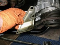
Lowering the triangular bracket (which cleaned up quite nicely at the time I removed it) into position, and re-installing the three 13mm bolts that hold it to the A/C compressor bracket and oilpan.

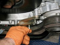
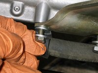
Installing the smaller 10mm bolt that holds the end of the bracket, and the clamp, to the oilpan.


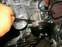
Next, with all of the tandem pump bolts installed, I re-installed the tandem pump pulley. The pulley as I removed it was a bit dirty on the inside, thanks to some years of Texas light-brownish sand and dirt. So, I did a quick wipe-down with some brake cleaner, and it cleaned up nicely.
Like the triangle bracket that I just re-installed, the tandem pump pulley is also held to the tandem pump's flange with three 13mm short bolts. I used my pulley holder tool to secure the pulley while I tightened all three of the pulley bolts in position.


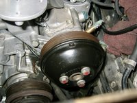
The last job I began preparing for, was the replacement of the two "short" braided SLS fluid hoses. These hoses go between the bottom of the SLS tank and the hard line on the passenger side, and also two hard lines on the driver's side. Neither of these hoses was leaking (I don't believe they are under much pressure), but they are original, and soft items in the engine compartment, and thus it was a good time to replace them.
In the course of thinking about this, I actually just decided to replace the entire SLS tank with the NOS MB factory spare tank that I have sitting in the shop. I have two new spares coming from Ntrepid, but why not use what I have? Most all of the fluid is drained, and no time like the present to do the job. I will also remove the SLS tank bracket, where it attaches to the inner fender-well, and clean up that area as well.
Back to the SLS short braided hoses. Both of them are specified by MB to be 130mm (13 cm) in length, so I had ordered a full meter of hose (you can only order it from MB by the meter), as it is fairly cheap. I cut two lengths of ~135mm, and will plan to replace the two lengths in the near future as I take care of re-attaching the lines to the tandem pump and remove/replace the SLS fluid reservoir. Here are a couple of photos of the "cutting."


The MB label indicated that the hose was made in Germany, and a quick sniff test of the rubber inside of the hose did confirm the presence of EU-made rubber, and the absence of Chinesium-rubber.
That's all for this installment .... thanks for your interest.
Cheers,
Gerry
Yesterday afternoon, I did a few little things in the re-assembly.
One small thing I've been trying to do in this job is to replace all of the degraded hardware and clamps that I come across. One of these degraded items were the clamps that hold the high-pressure SLS line, along the leading edge of the oilpan. Since I was replacing the triangular bracket that links and reinforces the A/C compressor to the oilpan, it seemed a good time to replace this clamp. I had ordered a supply of these clamps a couple of months ago from MB, so I had them right at hand and ready to go.
Here is the clamp installed on the high-pressure hose, ready for attachment.

Lowering the triangular bracket (which cleaned up quite nicely at the time I removed it) into position, and re-installing the three 13mm bolts that hold it to the A/C compressor bracket and oilpan.


Installing the smaller 10mm bolt that holds the end of the bracket, and the clamp, to the oilpan.


Next, with all of the tandem pump bolts installed, I re-installed the tandem pump pulley. The pulley as I removed it was a bit dirty on the inside, thanks to some years of Texas light-brownish sand and dirt. So, I did a quick wipe-down with some brake cleaner, and it cleaned up nicely.
Like the triangle bracket that I just re-installed, the tandem pump pulley is also held to the tandem pump's flange with three 13mm short bolts. I used my pulley holder tool to secure the pulley while I tightened all three of the pulley bolts in position.


The last job I began preparing for, was the replacement of the two "short" braided SLS fluid hoses. These hoses go between the bottom of the SLS tank and the hard line on the passenger side, and also two hard lines on the driver's side. Neither of these hoses was leaking (I don't believe they are under much pressure), but they are original, and soft items in the engine compartment, and thus it was a good time to replace them.
In the course of thinking about this, I actually just decided to replace the entire SLS tank with the NOS MB factory spare tank that I have sitting in the shop. I have two new spares coming from Ntrepid, but why not use what I have? Most all of the fluid is drained, and no time like the present to do the job. I will also remove the SLS tank bracket, where it attaches to the inner fender-well, and clean up that area as well.
Back to the SLS short braided hoses. Both of them are specified by MB to be 130mm (13 cm) in length, so I had ordered a full meter of hose (you can only order it from MB by the meter), as it is fairly cheap. I cut two lengths of ~135mm, and will plan to replace the two lengths in the near future as I take care of re-attaching the lines to the tandem pump and remove/replace the SLS fluid reservoir. Here are a couple of photos of the "cutting."


The MB label indicated that the hose was made in Germany, and a quick sniff test of the rubber inside of the hose did confirm the presence of EU-made rubber, and the absence of Chinesium-rubber.
That's all for this installment .... thanks for your interest.
Cheers,
Gerry
This afternoon I spent about 2.5 hours out in the shop, but they were a very productive time. Got a lot of little things done. Here's a summary.
First of all, and I didn't take photos, I spent about an hour under the car. I re-installed the last 13mm bolt that holds the back-side of the tandem pump bracket to the cylinder head, finishing that job and ensuring that the bracket is totally in place.
Then, I connected the 10mm bolt that holds the single ground wire to the bottom of the tandem pump bracket. Then I replaced another clamp (identical to the one in the previous post) that holds the high-pressure power steering hose to another portion of the oil pan.
After that, I took my 5mm Allen socket, because I noticed just a slight sweat of motor oil along the front edge of the oilpan, in the recess where the line of oilpan bolts are. I snugged each bolt down about 1/16 to 1/8 of a turn. Pretty much every single bolt needed a bit of a snugging down.
That pretty much was the end of my time under the car. Unfortunately I didn't take any photos, as it was tight quarters and I was sort of on a roll.
After the time under the car, I continued up top. Now that the tandem pump and bracket were attached, I could start reconnecting the lines to it, and replacing the two "soft" lengths of hose at the SLS fluid reservoir and at the tandem pump.
First though, I connected the large power steering line, per the two photos below.


Then it was time to turn attention to the short length of hose to the SLS portion of the pump. The original hose was a rubber hose on this side, but MB specifies in the ISPPI a length of braided rubber hose of the same diameter. Unfortunately, the 130mm (13cm) length for this hose as specified in the ISPPI is shorter than the original length, which I found after I removed it and compared the original hose (which was partially fossilized but semi-flexible) to the 130mm length I cut.
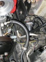


Measuring the remaining length of the meter of hose that I'd ordered, I lined it up next to the original hose and measured off an equivalent length. I cut it with my Dad's razor-sharp Ka-Bar knife. Went through it like butter.

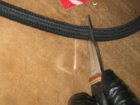
Then it was time to connect the newly cut hose to the pump. First, I removed the plug of lint-free towel, which kept dirt and debris out of the pump's nipple. Then, I inserted the hose clamps onto the center of the hose, and pushed it onto the nipple, as shown in the fourth and fifth photos below.


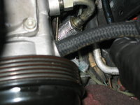

With the hose clamp in place, I tightened it into position.


Then, I did the same for the other side of the hose.


Next, it was time to connect the banjo bolt fitting to the tandem pump. Unfortunately, I did not quite have the correct size of copper washer in my parts stock, so I had to re-use the original washers. I'll have to re-order a dozen or so new ones of this size. Frustrating! But I'll replace them after I receive a new stock of them.

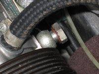

Next up, I decided to replace the other hose, which is attached directly to the bottom of the SLS fluid tank. I put the cut hose (130mm) up against the hose attached to the tank, and they WERE of the same length. So, at least for this hose, the ISPPI is correct.
As I got into the job, I decided to remove the three 10mm nuts that hold the SLS tank bracket to the engine compartment inner fender area. I found that two of these nuts were a bit rusty. One of the feet of the bracket also had some surface rust on it.


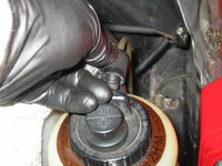


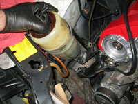
After removing the tank, I disassembled it and removed it from the bracket. You can see the darkness on the inside of the lower part of the bottle. This was staining due to sludge. The bottom of the tank had a slight layer of dark sludge in it.


A comparison of the two lengths of hose.

Here you can see the bracket, and the surface rust on the foot in the third photo. I was able to remove it with a wire brush.


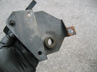
Tomorrow I'll continue and clean the area in the engine compartment where the SLS bottle bracket covered. Then, I will install my NOS SLS bottle. The two I've ordered from @Ntrepid will serve as my reserves. I will keep the original bottle as a spare, after cleaning out the inside of it.
By the way, the SLS reservoir brackets (124 320 13 43) are NLA from MB, so it's a good idea to maintain yours in good condition.
Cheers for your interest in this installment of the saga!
First of all, and I didn't take photos, I spent about an hour under the car. I re-installed the last 13mm bolt that holds the back-side of the tandem pump bracket to the cylinder head, finishing that job and ensuring that the bracket is totally in place.
Then, I connected the 10mm bolt that holds the single ground wire to the bottom of the tandem pump bracket. Then I replaced another clamp (identical to the one in the previous post) that holds the high-pressure power steering hose to another portion of the oil pan.
After that, I took my 5mm Allen socket, because I noticed just a slight sweat of motor oil along the front edge of the oilpan, in the recess where the line of oilpan bolts are. I snugged each bolt down about 1/16 to 1/8 of a turn. Pretty much every single bolt needed a bit of a snugging down.
That pretty much was the end of my time under the car. Unfortunately I didn't take any photos, as it was tight quarters and I was sort of on a roll.
After the time under the car, I continued up top. Now that the tandem pump and bracket were attached, I could start reconnecting the lines to it, and replacing the two "soft" lengths of hose at the SLS fluid reservoir and at the tandem pump.
First though, I connected the large power steering line, per the two photos below.


Then it was time to turn attention to the short length of hose to the SLS portion of the pump. The original hose was a rubber hose on this side, but MB specifies in the ISPPI a length of braided rubber hose of the same diameter. Unfortunately, the 130mm (13cm) length for this hose as specified in the ISPPI is shorter than the original length, which I found after I removed it and compared the original hose (which was partially fossilized but semi-flexible) to the 130mm length I cut.


Measuring the remaining length of the meter of hose that I'd ordered, I lined it up next to the original hose and measured off an equivalent length. I cut it with my Dad's razor-sharp Ka-Bar knife. Went through it like butter.


Then it was time to connect the newly cut hose to the pump. First, I removed the plug of lint-free towel, which kept dirt and debris out of the pump's nipple. Then, I inserted the hose clamps onto the center of the hose, and pushed it onto the nipple, as shown in the fourth and fifth photos below.


With the hose clamp in place, I tightened it into position.


Then, I did the same for the other side of the hose.


Next, it was time to connect the banjo bolt fitting to the tandem pump. Unfortunately, I did not quite have the correct size of copper washer in my parts stock, so I had to re-use the original washers. I'll have to re-order a dozen or so new ones of this size. Frustrating! But I'll replace them after I receive a new stock of them.


Next up, I decided to replace the other hose, which is attached directly to the bottom of the SLS fluid tank. I put the cut hose (130mm) up against the hose attached to the tank, and they WERE of the same length. So, at least for this hose, the ISPPI is correct.
As I got into the job, I decided to remove the three 10mm nuts that hold the SLS tank bracket to the engine compartment inner fender area. I found that two of these nuts were a bit rusty. One of the feet of the bracket also had some surface rust on it.


After removing the tank, I disassembled it and removed it from the bracket. You can see the darkness on the inside of the lower part of the bottle. This was staining due to sludge. The bottom of the tank had a slight layer of dark sludge in it.


A comparison of the two lengths of hose.

Here you can see the bracket, and the surface rust on the foot in the third photo. I was able to remove it with a wire brush.


Tomorrow I'll continue and clean the area in the engine compartment where the SLS bottle bracket covered. Then, I will install my NOS SLS bottle. The two I've ordered from @Ntrepid will serve as my reserves. I will keep the original bottle as a spare, after cleaning out the inside of it.
By the way, the SLS reservoir brackets (124 320 13 43) are NLA from MB, so it's a good idea to maintain yours in good condition.
Cheers for your interest in this installment of the saga!
Last edited:
I addition to snugging all the aforementioned bolts, I also added an external bead of RTV around the oil pan and timing cover-to-block seams. Definitely not @Klink-approved or Jono-approved, but it sure beats pulling the timing cover to stop tiny leak that mostly just makes a mess...After that, I took my 5mm Allen socket, because I noticed just a slight sweat of motor oil along the front edge of the oilpan, in the recess where the line of oilpan bolts are. I snugged each bolt down about 1/16 to 1/8 of a turn. Pretty much every single bolt needed a bit of a snugging down.

For the record, what type of RTV did/do you use? Just wondering what type would lend itself to this type of application?I also added an external bead of RTV around the oil pan and timing cover-to-block seams.
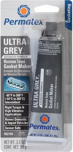
For an external bead like this, I don't think the specific type is critical. I believe the orange stuff in that photo was Permatex High-Temp (Ultra Copper?) but I'd have to check the tube. It worked very well.For the record, what type of RTV did/do you use? Just wondering what type would lend itself to this type of application?
I've tried some different smoo over the years and discovered certain types are easier to apply than others. For example, Permatex Right Stuff is too sticky, and difficult to apply/spread evenly - end result often isn't pretty. And I tried Permatex Ultra Black "oil-resistant" but IIRC, it was too thin/runny and didn't apply well either.

too bad that RTV does NOT come in an irridium silver color
It does! I use grey (looks silver) pro seal RTV sealant or clear where RTV is specified. Cannot sleep at night at the thought of glaring orange, red or blue RTV streaks in an engine compartment. God forbid
Among a few various and sundry parts I picked up today, this arrived --
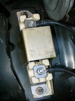
A new resistor, to replace the original one I've had all these years. I'll relegate the original one as a used spare, to join the other near-new used spare in my parts stock.
I see that it's made in JC's neighbor-land !!!
Note that this part is made by Beru. But it no longer seems to be offered on the aftermarket as a Beru part, like it used to be.


Today was about 5 hours out in the shop, and a lot of small things done.
The first thing I did was to give the exposed metal (which I'd removed the surface rust from) on the foot of the SLS fluid bracket, a couple of thin coats of Rust-Oleum black paint. Hopefully this should help keep any future corrosion away, at least for another decade or two.

Then it was time to clean the hardware with a wire brush, to get all of the surface rust off of the nuts. They cleaned up pretty nicely.

A rag soaked in brake cleaner made fairly short work of cleaning the area up under and around the SLS tank, including the side of the windshield washer fluid reservoir.

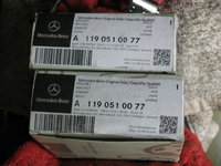
Looking ahead to the next job, I pulled out the two replacement cam solenoids I'd purchased a couple of months ago, and set them aside. I also got out my new tube of koala claw goo, which is also only a couple of months old. A couple of photos show a comparison of the old and new tubes of goo.


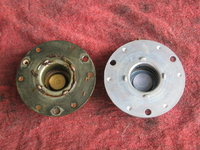
And a couple of comparison shots of the original and replacement cam solenoids. Note that the original solenoids are nicely finished. The replacements not so much. Manufacturer is still the same company.

After the paint had dried on the SLS fluid tank bracket, it was time to lower it into place, and tighten down the three 10mm nuts that held it into place. I put a couple of drops of oil onto the threads of each pin, to make the tightening of the nuts a bit easier.

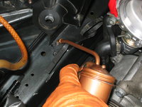


Then I slid the second clamp onto the short hose. After that, I moved the spring down onto the top of the tank, and got it nearly into place. A hooked tool helped move the spring downward, once I'd installed the SLS fluid bottle into its bracket.


Then I connected the hydraulic fluid return hose, at the top of the cap on the fluid bottle, and tightened it down.


And here's what a new SLS bottle looks like. Quite a difference from the old one.

The last step was to re-attach the short braided hose from the bottom of the SLS fluid bottle to the hard line. This was done with ease, and the remaining clamp tightened into place.


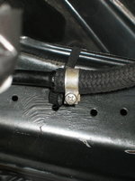

And here's the hose and SLS fluid bottle, re-installed and ready to go.

Picking up where I left off, it was time to install the two new cam solenoids. Using a Q-tip, I smeared the sealing surface of the solenoid with the orange koala-claw goo in as even of a coat as I could. Then I pushed the three bolts through, and added some goo to their threads, as well.


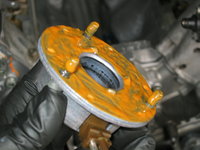
Then I installed the solenoid into the proper position, and began threading the bolts into the front cylinder head cover with my fingers. A small 1/4" torque wrench made short work of torquing the three bolts. I snugged each one down to 5 Nm, and then successively torqued each bolt to its specified 10Nm (which was just off the scale of the torque wrench). I used a 1/4" ratchet to ensure that each of the 5mm Allen bolts was snugged down into position.
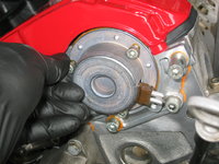


Then, I repeated the exact same process on the left (driver's) side.


Here's a front view of the engine, with the cam solenoids attached.

The next task was to remove the front headlight, so I could get to the series resistor and two coils located behind it, for replacement in the coming days. Removing the headlight is a pretty straightforward task, and generally requires only an 8mm wrench and/or socket.


Note that after the headlight wiper was removed, the rubber wiper insert is beginning to tear, necessitating the procurement of a new pair of windshield wipers, so that I can cut them down to proper length to fit the headlight wipers.

Continuing on with the removal of the left-side headlight.
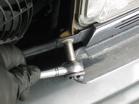


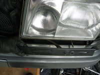


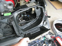
With the headlight out, the plastic air scoop is exposed. This is held in by four small bolts, which I removed.


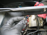
I removed the large piece of forked foam under the turn signal.

And here's the headlight area, with the air scoop removed. Note the rectangular piece of foam that sits underneath it. It wasn't quite as degraded as the passenger side, but it will be replace nonetheless, because I had already cut a replacement piece for it.
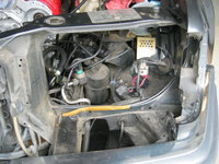

Another couple of views of the area behind the headlight, from THROUGH the headlight, and from above.
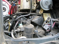

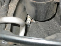
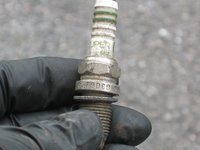
Inspecting the area, I found an old spark plug that had dropped down into the crevasse, as well as a rusty razor blade. Looking at the spark plug, it was DEFINITELY not one of mine, looking at the Bosch plug number. BUT, it was a Bosch Super non-resistor plug, so at least it had that going for it. It must have been accidentally dropped down there by a mechanic prior to my ownership of the car as of 2003.


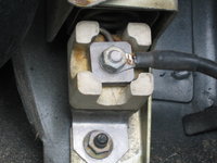
Turning my attention to the series resistor, I removed the two small nuts that held the resistor to the body, as well as the two nuts that held the connections to the ends of the resistor. It was not in BAD shape, but certainly warranted the $35 for a replacement.


A few more views of the resistor as removed from the car.


Here's what things look like with the resistor removed.

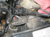
Next it was time to remove the coils. First I removed the black plastic covers. They were quite dirty.


Then I took photos the two 10mm nuts and bolts that held each of the coils to the car's body, so that I can re-install them in the correct orientation for re-assembly.
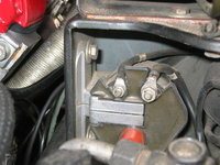


Funnily enough, the rubber drain grommet in the plastic air scoop had been eaten away by rodents, just like the passenger side. Since I had ordered two of them, I replaced it straightaway as I cleaned up the air scoop.

The two black plastic coil covers also cleaned up quite nicely.

Then I removed the two coils. Four bolts to loosen the coils, and four nuts and washers to loosen the electrical connections to the coils (one 8mm and one 10mm nut per coil).
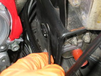

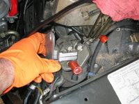


I do not believe it is possible to remove the coils, without first removing the headlight. It is VERY tight in there, even with the headlight out !! These original coils did a yeoman's job for 142k miles, but I will save them as reserve spares after cleaning them up.
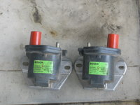
The two electrical leads to the right side were marked with little white "R" tags on each lead, but they had dried out and were falling off the leads. To keep them together, I took a piece of Scotch tape and taped the two "R" leads together, to make re-assembly easier.

Next I removed the horn, and moved it upward and out of the way so I could clean behind and under it.

And lastly, I started cleaning the area behind and under the headlight, with the coils, resistor and horn out of the way. First is a "before" shot, and next is a "during" shot. I'll publish an "after" shot before I start re-assembling everything. My new coils are slated to arrive on Monday.


Thanks for your continuing interest !!
The first thing I did was to give the exposed metal (which I'd removed the surface rust from) on the foot of the SLS fluid bracket, a couple of thin coats of Rust-Oleum black paint. Hopefully this should help keep any future corrosion away, at least for another decade or two.

Then it was time to clean the hardware with a wire brush, to get all of the surface rust off of the nuts. They cleaned up pretty nicely.

A rag soaked in brake cleaner made fairly short work of cleaning the area up under and around the SLS tank, including the side of the windshield washer fluid reservoir.

Looking ahead to the next job, I pulled out the two replacement cam solenoids I'd purchased a couple of months ago, and set them aside. I also got out my new tube of koala claw goo, which is also only a couple of months old. A couple of photos show a comparison of the old and new tubes of goo.


And a couple of comparison shots of the original and replacement cam solenoids. Note that the original solenoids are nicely finished. The replacements not so much. Manufacturer is still the same company.


After the paint had dried on the SLS fluid tank bracket, it was time to lower it into place, and tighten down the three 10mm nuts that held it into place. I put a couple of drops of oil onto the threads of each pin, to make the tightening of the nuts a bit easier.


Then I slid the second clamp onto the short hose. After that, I moved the spring down onto the top of the tank, and got it nearly into place. A hooked tool helped move the spring downward, once I'd installed the SLS fluid bottle into its bracket.


Then I connected the hydraulic fluid return hose, at the top of the cap on the fluid bottle, and tightened it down.


And here's what a new SLS bottle looks like. Quite a difference from the old one.

The last step was to re-attach the short braided hose from the bottom of the SLS fluid bottle to the hard line. This was done with ease, and the remaining clamp tightened into place.


And here's the hose and SLS fluid bottle, re-installed and ready to go.

Picking up where I left off, it was time to install the two new cam solenoids. Using a Q-tip, I smeared the sealing surface of the solenoid with the orange koala-claw goo in as even of a coat as I could. Then I pushed the three bolts through, and added some goo to their threads, as well.


Then I installed the solenoid into the proper position, and began threading the bolts into the front cylinder head cover with my fingers. A small 1/4" torque wrench made short work of torquing the three bolts. I snugged each one down to 5 Nm, and then successively torqued each bolt to its specified 10Nm (which was just off the scale of the torque wrench). I used a 1/4" ratchet to ensure that each of the 5mm Allen bolts was snugged down into position.


Then, I repeated the exact same process on the left (driver's) side.


Here's a front view of the engine, with the cam solenoids attached.

The next task was to remove the front headlight, so I could get to the series resistor and two coils located behind it, for replacement in the coming days. Removing the headlight is a pretty straightforward task, and generally requires only an 8mm wrench and/or socket.


Note that after the headlight wiper was removed, the rubber wiper insert is beginning to tear, necessitating the procurement of a new pair of windshield wipers, so that I can cut them down to proper length to fit the headlight wipers.

Continuing on with the removal of the left-side headlight.


With the headlight out, the plastic air scoop is exposed. This is held in by four small bolts, which I removed.


I removed the large piece of forked foam under the turn signal.

And here's the headlight area, with the air scoop removed. Note the rectangular piece of foam that sits underneath it. It wasn't quite as degraded as the passenger side, but it will be replace nonetheless, because I had already cut a replacement piece for it.


Another couple of views of the area behind the headlight, from THROUGH the headlight, and from above.


Inspecting the area, I found an old spark plug that had dropped down into the crevasse, as well as a rusty razor blade. Looking at the spark plug, it was DEFINITELY not one of mine, looking at the Bosch plug number. BUT, it was a Bosch Super non-resistor plug, so at least it had that going for it. It must have been accidentally dropped down there by a mechanic prior to my ownership of the car as of 2003.


Turning my attention to the series resistor, I removed the two small nuts that held the resistor to the body, as well as the two nuts that held the connections to the ends of the resistor. It was not in BAD shape, but certainly warranted the $35 for a replacement.


A few more views of the resistor as removed from the car.


Here's what things look like with the resistor removed.


Next it was time to remove the coils. First I removed the black plastic covers. They were quite dirty.


Then I took photos the two 10mm nuts and bolts that held each of the coils to the car's body, so that I can re-install them in the correct orientation for re-assembly.


Funnily enough, the rubber drain grommet in the plastic air scoop had been eaten away by rodents, just like the passenger side. Since I had ordered two of them, I replaced it straightaway as I cleaned up the air scoop.

The two black plastic coil covers also cleaned up quite nicely.

Then I removed the two coils. Four bolts to loosen the coils, and four nuts and washers to loosen the electrical connections to the coils (one 8mm and one 10mm nut per coil).


I do not believe it is possible to remove the coils, without first removing the headlight. It is VERY tight in there, even with the headlight out !! These original coils did a yeoman's job for 142k miles, but I will save them as reserve spares after cleaning them up.

The two electrical leads to the right side were marked with little white "R" tags on each lead, but they had dried out and were falling off the leads. To keep them together, I took a piece of Scotch tape and taped the two "R" leads together, to make re-assembly easier.

Next I removed the horn, and moved it upward and out of the way so I could clean behind and under it.

And lastly, I started cleaning the area behind and under the headlight, with the coils, resistor and horn out of the way. First is a "before" shot, and next is a "during" shot. I'll publish an "after" shot before I start re-assembling everything. My new coils are slated to arrive on Monday.


Thanks for your continuing interest !!
Looks good GVZ. I have some Captruff Spray wax as you dry and for areas in the engine bay susceptible to dirt collection on the E and the C126, it is really nice to wipe down that painted sheet metal with the spray wax before you assemble it all. Since you are there, perhaps some hot rod sleeve on the wire harness of the resistor...I rebuilt mine as the PO job was lacking. I used 10g copper wire for the rebuild.
Interesting comment on your water pump. My '94 E500 also has the original water pump at 126,000 miles. Would you recommend replacement as a preventative measure?I've also decided overnight and this morning that I am going to replace the water pump, along with the planned thermostat replacement. Reason being is that I have done all of the work that would be pre-required to do the water pump, and drained the coolant. I have a spare, new water pump and gasket sitting on the shelf in the garage, and the water pump on the engine is the original one (144K miles).
It's literally incremental labour to replace the pump at this point. So, yet another task to do as part of this big job.
Thx
No. I’d only replace it if it is leaking. The only reason I replaced it is because I had the rest of the front of the engine apart to do other work. Literally it was 20 minutes of work to replace the pump with everything off.
It’s a bit of a pain to do the water pump because of the harmonic balancer, which blocks access to one of the bolts unless you really know what you’re doing. So quite often the balancer and crank pulley have to come off to do the water pump. I was taking them off anyway to replace the front crank seal — a hugely common oil leak point on the M119.
It’s a bit of a pain to do the water pump because of the harmonic balancer, which blocks access to one of the bolts unless you really know what you’re doing. So quite often the balancer and crank pulley have to come off to do the water pump. I was taking them off anyway to replace the front crank seal — a hugely common oil leak point on the M119.
On Wednesday, at a couple of points during the day, I spent about 2.5 hours out in the shop working on a few items as I put things back together. Here's an overview of what I worked on.
First, I continued cleaning up the driver's side headlight area, in reparation for the re-installation of the new coils and series resistor for the blower motor. Here's how the headlight area was shaping up as I progressed.....
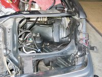
I grabbed the new resistor, and prepared it for re-installation.


I realized that I had not soaked and cleaned the hardware for the resistor, nor for the alarm horn, so I put it in a small container of cleaner for 15-20 minutes. While the hardware was soaking, I turned over to the power steering reservoir. First, with a shop rag infused with a bit of brake cleaner, I did a final "clean-off" of the pedestal that supports the reservoir. Then with some needle-nose pliers, I carefully removed the bit of lint-free towel that I had plugging the opening down to the tandem pump against any dirt intrusion.


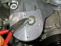
Then I grabbed the factory power steering pump reservoir gasket (a Reinz -- EEK! -- gasket that I had replaced new when I rebuilt the tandem pump a few years back ..... this is a $30 gasket from MB!!) and examined it. It was in grand condition, so easily able to be re-used. And so I did.

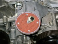

Place the reservoir into position on top of the pedestal and gasket, and line up the screw holes.


Remember, these are "female Torx" screws, so they take a special socket. A magnetic pickup put the bolts into the proper position, and then I snugged them down. I also replaced the two small 10mm bolts that held the return line to the back of the reservoir. Again, the o-ring for this return line flange had been replaced just a few years ago, and was in great condition, so I didn't bother to replace it.


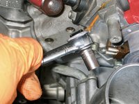

With things partially assembled, I put the cap onto the top of the reservoir temporarily, until I could finish the job.

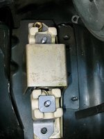
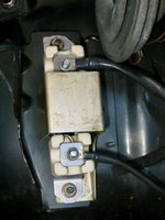
After retrieving the hardware from its cleaning container and drying it, it was time to install the resistor into its position. Only two small 8mm nuts and lock-washers hold the resistor to the inner fender area, as well as two 8mm nuts and lock-washers to fasten the two wires to the resistor. I also wrote the date on the resistor with a Sharpie marker, for future reference. Examining the wires that connect to the resistor, both of them were in good shape -- no corrosion or degradation -- so I re-attached them and cinched down the nuts and washers.


Chase was laying down in the relatively cooler environs of the garage, and watching me with half interest....


Next, it was time to install the new Bosch coils that I'd received on Monday. One of the coil boxes was a very old-school "yellow" Bosch box, leading me to believe this coil had been made some years ago. Both coils were made in Slovenia, where Bosch has been making their coils for at least the past 12-15 years. I also wrote the date on the two coils before I installed them.


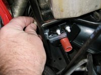

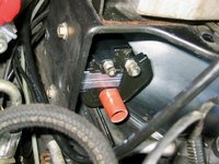

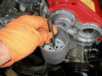
With the coils in place, I turned my attention back to the power steering fluid reservoir to finish out that job. This was a matter of re-installing a new filter, the center spring and fluid level indicator. Note that (as per usual) I dated and initialed the power steering filter. This was a filter I'd purchased way back in late 2013.

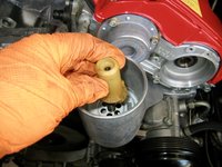

I put the cap back onto the housing to keep dirt and dust out, until it is time to re-fill the reservoir with fresh MB PS fluid.

Next, with the coils and resistor installed, I re-attached the horn for the car alarm. This is held quite nicely by a small bracket that attaches to the end of the horn's arm, and a single 13mm bolt.
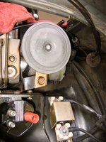

One note — I decided to leave off the metal housing that fits on top of the series resistor. This is per the advice of @Klink in the past -- this metal cover (though with holes drilled into it) restricts proper airflow onto the resistor, which relies on natural cooling, and helps prolong the resistor's life, and the integrity of the wires that attach to it. So, I left it off, and relegate it to my parts collection.

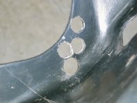
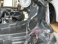
The plastic headlight air scoop/bucket piece, as shown in the first photo below, has a SINGLE, dime-sized hole that allows air to flow back to the resistor when the car is in motion. To provide additional airflow and circulation to the resistor (in addition to removing the cover in the above step), I drilled a few more holes near the original single dime-sized hole with my drill press. Although not very pretty, no one will EVER see these holes, and they will hopefully provide MUCH more incremental air to the resistor area once fitted.

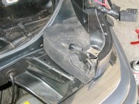
Next, I added the "fingered" foam piece that fits behind the corner of the bumper. Had to flip it to the correct orientation from the first photo, but the second photo shows things all emplaced nicely.

From there, it was time to connect the wires to the coils. Each coil has two wires -- one connecting with a small 8mm nut and lock-washer, and the other with a 10mm nut and lock-washer. These were relatively easy to connect.
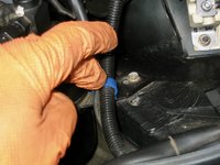


One thing I did was to re-add, using a bit of Super-glue, the "R" labels around the two wires leading to the coil that feeds the right-side distributor cap. Hopefully these labels will remain glued for another 20-25 years to the coil wires.


I made the final connections, tightened them down, and then added the two plastic coil caps.


And that was the end of the time that I had, at least for Wednesday's work.
Thanks for your interest!
Cheers,
Gerry
First, I continued cleaning up the driver's side headlight area, in reparation for the re-installation of the new coils and series resistor for the blower motor. Here's how the headlight area was shaping up as I progressed.....

I grabbed the new resistor, and prepared it for re-installation.


I realized that I had not soaked and cleaned the hardware for the resistor, nor for the alarm horn, so I put it in a small container of cleaner for 15-20 minutes. While the hardware was soaking, I turned over to the power steering reservoir. First, with a shop rag infused with a bit of brake cleaner, I did a final "clean-off" of the pedestal that supports the reservoir. Then with some needle-nose pliers, I carefully removed the bit of lint-free towel that I had plugging the opening down to the tandem pump against any dirt intrusion.


Then I grabbed the factory power steering pump reservoir gasket (a Reinz -- EEK! -- gasket that I had replaced new when I rebuilt the tandem pump a few years back ..... this is a $30 gasket from MB!!) and examined it. It was in grand condition, so easily able to be re-used. And so I did.


Place the reservoir into position on top of the pedestal and gasket, and line up the screw holes.


Remember, these are "female Torx" screws, so they take a special socket. A magnetic pickup put the bolts into the proper position, and then I snugged them down. I also replaced the two small 10mm bolts that held the return line to the back of the reservoir. Again, the o-ring for this return line flange had been replaced just a few years ago, and was in great condition, so I didn't bother to replace it.


With things partially assembled, I put the cap onto the top of the reservoir temporarily, until I could finish the job.

After retrieving the hardware from its cleaning container and drying it, it was time to install the resistor into its position. Only two small 8mm nuts and lock-washers hold the resistor to the inner fender area, as well as two 8mm nuts and lock-washers to fasten the two wires to the resistor. I also wrote the date on the resistor with a Sharpie marker, for future reference. Examining the wires that connect to the resistor, both of them were in good shape -- no corrosion or degradation -- so I re-attached them and cinched down the nuts and washers.


Chase was laying down in the relatively cooler environs of the garage, and watching me with half interest....


Next, it was time to install the new Bosch coils that I'd received on Monday. One of the coil boxes was a very old-school "yellow" Bosch box, leading me to believe this coil had been made some years ago. Both coils were made in Slovenia, where Bosch has been making their coils for at least the past 12-15 years. I also wrote the date on the two coils before I installed them.


With the coils in place, I turned my attention back to the power steering fluid reservoir to finish out that job. This was a matter of re-installing a new filter, the center spring and fluid level indicator. Note that (as per usual) I dated and initialed the power steering filter. This was a filter I'd purchased way back in late 2013.


I put the cap back onto the housing to keep dirt and dust out, until it is time to re-fill the reservoir with fresh MB PS fluid.

Next, with the coils and resistor installed, I re-attached the horn for the car alarm. This is held quite nicely by a small bracket that attaches to the end of the horn's arm, and a single 13mm bolt.


One note — I decided to leave off the metal housing that fits on top of the series resistor. This is per the advice of @Klink in the past -- this metal cover (though with holes drilled into it) restricts proper airflow onto the resistor, which relies on natural cooling, and helps prolong the resistor's life, and the integrity of the wires that attach to it. So, I left it off, and relegate it to my parts collection.

The plastic headlight air scoop/bucket piece, as shown in the first photo below, has a SINGLE, dime-sized hole that allows air to flow back to the resistor when the car is in motion. To provide additional airflow and circulation to the resistor (in addition to removing the cover in the above step), I drilled a few more holes near the original single dime-sized hole with my drill press. Although not very pretty, no one will EVER see these holes, and they will hopefully provide MUCH more incremental air to the resistor area once fitted.


Next, I added the "fingered" foam piece that fits behind the corner of the bumper. Had to flip it to the correct orientation from the first photo, but the second photo shows things all emplaced nicely.


From there, it was time to connect the wires to the coils. Each coil has two wires -- one connecting with a small 8mm nut and lock-washer, and the other with a 10mm nut and lock-washer. These were relatively easy to connect.


One thing I did was to re-add, using a bit of Super-glue, the "R" labels around the two wires leading to the coil that feeds the right-side distributor cap. Hopefully these labels will remain glued for another 20-25 years to the coil wires.


I made the final connections, tightened them down, and then added the two plastic coil caps.


And that was the end of the time that I had, at least for Wednesday's work.
Thanks for your interest!
Cheers,
Gerry
Trivia: The existing hole is not for airflow to the resistor. There is supposed to be a short rubber hose connecting a hose barb on the headlight, that routes out through that hose. This keeps pressure from the "airbox" around the headlight from entering the headlight, potentially causing condensation to be pushed into the headlight housing.The plastic headlight air scoop/bucket piece, as shown in the first photo below, has a SINGLE, dime-sized hole that allows air to flow back to the resistor when the car is in motion.
View attachment 109667
The same headlight ventilation system is used on all 034/036.
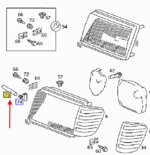
In response to a couple of folks who have asked about the so-called "finger foam" piece at the inside of the corners of the bumpers and fender area:
Part numbers are 124 628 51 98 (right side) and 124 628 55 98 (left side).
Both pieces are NLA from MB. RevParts sites say that both are available. Do not believe them.

Part numbers are 124 628 51 98 (right side) and 124 628 55 98 (left side).
Both pieces are NLA from MB. RevParts sites say that both are available. Do not believe them.
Spent about 1.75 hours out in the shop this morning, doing a few miscellaneous and sundry tasks.
I decided to finish up a few things that I had not done UNDERNEATH the car.
First was to tighten and torque down the transmission pan bolts. I'd done this when I installed the pan, with the new gasket, but wanted to give things a little time to compress before I checked tightness again. All were quite tight. The torque value for the transmission pan bolts is 8Nm. I think I had mine around 10Nm, so slightly over-tightened, but not enough to bend the pan.
The next task was to re-install the "S" hose that connects the power steering reservoir and the tandem pump. I thought this was going to be more of a PITA than it was -- the job only took about 5 minutes. I took some brake cleaner and cleaned off the aluminum heat shielding, which was in pretty good shape from being replaced some years back, when I did the tandem pump rebuild.
I did re-orient one of the clamps so that it could be accessed from UNDER the car, along with the other clamp, rather than facing upward so that I had to loosen it from inside the engine compartment. The ends slid right onto the ends of the hard lines, and the clamps tightened up just fine with a long, flat-blade screwdriver.


Then, with the "S" hose done, it was time to re-install the driver's side air scoop and ducting that provide cooling air to the motor mount on that side. Again, this was fairly easy. The first photo provides an overview of the scoop and ducting. The second photos show the two places that the ducting mount to the car's frame: 1) a 10mm plastic nut (shown in the second photo) near the lower control arm; and 2) an 8mm screw that goes into a thin metal piece welded to the car's body, which fits vertically into a slot in the ducting piece. The screw secures the metal to the duct.


Fitting two of the pieces of ducting together as I wrestle them into place.


Fitting the 8mm screw into the vertical metal piece fitted into the slot in the ducting piece. Then tightening up the screw.

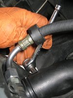
Tightening the 10mm plastic nut that holds the last ducting piece to the frame.

Ensuring that the "scoop" is properly fitted to its area in the front spoiler, directly inboard of the driver's side fog-lamp.

The last job under the car, at least for now, was to re-fit the flywheel lock into the transmission. This is the last step in preparation of the torquing down of the crankshaft bolt, including the crank pulley and harmonic balancer. After slightly rotating the crank bolt (temporarily installed some time back) into an appropriate position, I was able to insert the flywheel lock into position, and tap it lightly into place with a claw hammer (nod to @JC220). Now I can lower the car and torque the center crank bolt down to its full 400 Nm (300 lb-ft), which I will do in the near future.

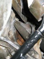
The last job for the morning was to begin re-installing the headlight, turn signal and plastic headlight air scoop. I managed to wrestle it back into place with only a little difficulty, and then work the hood cable and the headlight/turn signal wiring bundle through the scoop into their proper positions. Four small 8mm screws hold the scoop into place on the car's front structure.


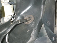
Here are the extra holes I recently drilled, in relating to the more-exposed series resistor. The bottom-most hole is the hole where the rubber short hose from the rear corner of the headlight will be inserted, but hopefully there will now be a bit more air-flow into the resistor area, helping keep it and its wiring a little cooler than before.

That's all for now -- I expect another session out in the garage later today.
Cheers,
Gerry
I decided to finish up a few things that I had not done UNDERNEATH the car.
First was to tighten and torque down the transmission pan bolts. I'd done this when I installed the pan, with the new gasket, but wanted to give things a little time to compress before I checked tightness again. All were quite tight. The torque value for the transmission pan bolts is 8Nm. I think I had mine around 10Nm, so slightly over-tightened, but not enough to bend the pan.
The next task was to re-install the "S" hose that connects the power steering reservoir and the tandem pump. I thought this was going to be more of a PITA than it was -- the job only took about 5 minutes. I took some brake cleaner and cleaned off the aluminum heat shielding, which was in pretty good shape from being replaced some years back, when I did the tandem pump rebuild.
I did re-orient one of the clamps so that it could be accessed from UNDER the car, along with the other clamp, rather than facing upward so that I had to loosen it from inside the engine compartment. The ends slid right onto the ends of the hard lines, and the clamps tightened up just fine with a long, flat-blade screwdriver.


Then, with the "S" hose done, it was time to re-install the driver's side air scoop and ducting that provide cooling air to the motor mount on that side. Again, this was fairly easy. The first photo provides an overview of the scoop and ducting. The second photos show the two places that the ducting mount to the car's frame: 1) a 10mm plastic nut (shown in the second photo) near the lower control arm; and 2) an 8mm screw that goes into a thin metal piece welded to the car's body, which fits vertically into a slot in the ducting piece. The screw secures the metal to the duct.


Fitting two of the pieces of ducting together as I wrestle them into place.


Fitting the 8mm screw into the vertical metal piece fitted into the slot in the ducting piece. Then tightening up the screw.


Tightening the 10mm plastic nut that holds the last ducting piece to the frame.

Ensuring that the "scoop" is properly fitted to its area in the front spoiler, directly inboard of the driver's side fog-lamp.

The last job under the car, at least for now, was to re-fit the flywheel lock into the transmission. This is the last step in preparation of the torquing down of the crankshaft bolt, including the crank pulley and harmonic balancer. After slightly rotating the crank bolt (temporarily installed some time back) into an appropriate position, I was able to insert the flywheel lock into position, and tap it lightly into place with a claw hammer (nod to @JC220). Now I can lower the car and torque the center crank bolt down to its full 400 Nm (300 lb-ft), which I will do in the near future.


The last job for the morning was to begin re-installing the headlight, turn signal and plastic headlight air scoop. I managed to wrestle it back into place with only a little difficulty, and then work the hood cable and the headlight/turn signal wiring bundle through the scoop into their proper positions. Four small 8mm screws hold the scoop into place on the car's front structure.


Here are the extra holes I recently drilled, in relating to the more-exposed series resistor. The bottom-most hole is the hole where the rubber short hose from the rear corner of the headlight will be inserted, but hopefully there will now be a bit more air-flow into the resistor area, helping keep it and its wiring a little cooler than before.

That's all for now -- I expect another session out in the garage later today.
Cheers,
Gerry
Another couple of hours out in the shop in the late afternoon / early evening, doing a few more tasks before we had family come over for a true Maryland crab feast at the kitchen table. We bought a full bushel of crabs ... that's 9 or 10 dozen steaming hot blue crabs in a very large box.
Had to leave at 6PM to drive over to the US Naval Academy Memorial Stadium, to pick them up, as the Annapolis Rotary Club was doing its annual crab fest. Unfortunately this year, it was drive-up service only to pick up the crabs. Most years you go into the stadium and it's a giant crab feast.
Anyhoo, here's what I did before we had to bail.
It was finally time to complete the build-out of the new water pump. First thing to do was to install the new thermostat, and thermostat gasket. As I'd shown very early in this series, there is one small spot of corrosion on the thermostat housing where the hose attaches, as shown below. It's not bad, but I will put a new thermostat housing on my parts order list, for a few years down the road when I change the thermostat the next time. This is not an expensive part.


Pulled the new thermostat out of parts stock. It came in a BorgWarner box, but it's a gen-u-whine Wahler unit, made in Germany. I have been using Behr for many years, but have had bad luck with them in recent years, so I'm going to try out a Wahler to see if it is better. If so, I'll order up a few for the M119 and M117.


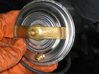
Here's the water pump, with the openings blocked with lint-free towel pieces. I removed the towel piece on the side, where the thermostat goes.

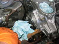
Then I inserted the thermostat into the housing, with the correct orientation. The small tube must be at the top, so I aligned it with the top bolt hole.


Placing the black rubber thermostat housing gasket into position, I pressed the thermostat housing onto the side of the water pum0, and put the bolts in place to hold things for future torquing.


Next, it was time to turn my attention to the housing at the TOP of the water pump. This is where the thick coolant hose from the intake manifold attaches. Also, two of its bolts hold down the lifting lug at the front side of the engine. There is a special paper gasket for this housing, as you can see in the photos below. It fits in only one orientation, so it's hard to mess this one up.
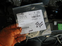


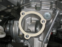
Placing the housing into position, and inserting the three bolts and lifting lug. The two longer bolts go through the lug, of course.


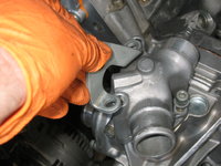


Torquing the top housing bolts down to their 21Nm of torque.
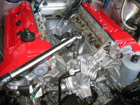
And, a few views of the installed top housing. Again, you see a bit of aluminum corrosion on the hose connection. It's not horrible, but I will need to replace this piece in the future, as it is a potential leak point.


Then I torqued down the thermostat housing bolts to their proper 10Nm of torque. Easy enough. Water pump DONE.

I next turned my attention to the headlight washer hoses. These had been exposed during my headlight removal and work underneath the front of the car. These hoses are original to the car, and thus a bit hardened and brown. They are particularly hardened where exposed to engine heat. I removed (as shown in the second photo below) the long length of hose that runs immediately behind the bumper from the passenger side to the driver's side headlight squirter.


With part of the hoses removed, I cut new lengths as they go from the valve to the passenger and driver's side headlight squirters. The open part on the valve is the "feed" line that goes directly from the second pump in the bottom of the windshield washer housing, to the headlight squirters. I'll replace this feed line (which is a very short line) at a later date. It has a special wire clamp that secures it to the pump's output.


As you can see, the cardboard box of removed/old parts that have been replaced is growing rapidly!! When the job is done, I'll lay all of these out so you guys can see the extent of "soft" parts that have been replaced.

Here's a view of the routing of the new squirter line from the passenger side to the driver's side, behind the bumper. It just goes through a number of plastic clips that secure it in place.

The next job was to replace the headlight and turn signal back into the car. The headlight's lens was newly Lamin-X'd, so it was ready to go. I did a cursory cleaning of the plastic body of the headlight before carefully inserting it into the headlight bucket.


Then secured it with the 8mm screws into the car's body.


Here's what the headlight looks like, preliminarily mounted.

After the headlight is in place, it's time to mount the under-light strip. This is a @Jimbo-brand strip, that I bought from him many years ago. Holding up well, though it has some rock dings and could use a strip and a repaint. When I do this, I will definitely add a layer of Lamin-X to the strip to protect it. These strips take a major beating from rocks and sand-blasting.
The strips have to be finessed into place and CAREFULLY adjusted. You also have to attach the end of the headligiht squirter hose to the squirter itself, and insert the headlight wiper blade shaft through the hole in the strip. THEN you have to line everything up, and tighten it all down.
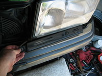


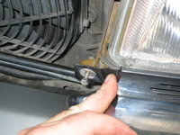
You can see here that the edge of the headlight is not quite into place. The headlight needs to be flush with the top edge of the strip, and the end of the strip needs to be flush with the end of the curved edge of the fender. It's a bit of a dance to get things to line up, but it just takes a bit of time and patience to get it all nailed.


Don't forget the plastic piece that goes into the upper radiator support!!

Attach the rubber squirter line to the valve, and then put the wiper onto its shaft and tighten down the 8mm shaft nut. Not too tight !!

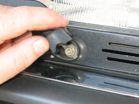
After getting the headlight adjusted and everything aligned, here's what it looks like. After I did this, I pushed in and locked the turn signal as well. All looks very nice!!

Lastly, I turned my attention to the crank bolt and pulley. With the flywheel locket, I could remove the snugged down crank bolt (which I'd used in the past to rotate the engine). Didn't take too much effort to loosen the crank center bolt and its four washers.


Here is the orientation of the crank after I turned it a bit, while finding a position under the car where I could insert the flywheel lock.

Removing the bolts that I'd used to attach the harmonic balancer to the hub. I had done this some time back so that I had an accurate representaiton of where to align the crank, for the timing chain rail work that I'd done. The balancer and its bolts needed to come off so that I could attach the crank pulley.

The next step was to re-install the balancer and pulley combination, and re-bolt and torque everything down. The torque for the six crank pulley bolts was 35Nm. The second photo below shows the torquing process. I used a cross-pattern of tightening and torquing down the balancer+pulley combination.

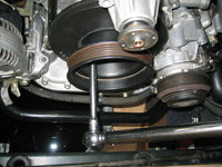
And this last photo is for JC220...... my extra parts stock of "proper" 722.3 pan magnets.

Thank for looking, and more action soon !!
Cheers,
Gerry
Had to leave at 6PM to drive over to the US Naval Academy Memorial Stadium, to pick them up, as the Annapolis Rotary Club was doing its annual crab fest. Unfortunately this year, it was drive-up service only to pick up the crabs. Most years you go into the stadium and it's a giant crab feast.
Anyhoo, here's what I did before we had to bail.
It was finally time to complete the build-out of the new water pump. First thing to do was to install the new thermostat, and thermostat gasket. As I'd shown very early in this series, there is one small spot of corrosion on the thermostat housing where the hose attaches, as shown below. It's not bad, but I will put a new thermostat housing on my parts order list, for a few years down the road when I change the thermostat the next time. This is not an expensive part.


Pulled the new thermostat out of parts stock. It came in a BorgWarner box, but it's a gen-u-whine Wahler unit, made in Germany. I have been using Behr for many years, but have had bad luck with them in recent years, so I'm going to try out a Wahler to see if it is better. If so, I'll order up a few for the M119 and M117.


Here's the water pump, with the openings blocked with lint-free towel pieces. I removed the towel piece on the side, where the thermostat goes.


Then I inserted the thermostat into the housing, with the correct orientation. The small tube must be at the top, so I aligned it with the top bolt hole.


Placing the black rubber thermostat housing gasket into position, I pressed the thermostat housing onto the side of the water pum0, and put the bolts in place to hold things for future torquing.


Next, it was time to turn my attention to the housing at the TOP of the water pump. This is where the thick coolant hose from the intake manifold attaches. Also, two of its bolts hold down the lifting lug at the front side of the engine. There is a special paper gasket for this housing, as you can see in the photos below. It fits in only one orientation, so it's hard to mess this one up.


Placing the housing into position, and inserting the three bolts and lifting lug. The two longer bolts go through the lug, of course.


Torquing the top housing bolts down to their 21Nm of torque.

And, a few views of the installed top housing. Again, you see a bit of aluminum corrosion on the hose connection. It's not horrible, but I will need to replace this piece in the future, as it is a potential leak point.


Then I torqued down the thermostat housing bolts to their proper 10Nm of torque. Easy enough. Water pump DONE.

I next turned my attention to the headlight washer hoses. These had been exposed during my headlight removal and work underneath the front of the car. These hoses are original to the car, and thus a bit hardened and brown. They are particularly hardened where exposed to engine heat. I removed (as shown in the second photo below) the long length of hose that runs immediately behind the bumper from the passenger side to the driver's side headlight squirter.


With part of the hoses removed, I cut new lengths as they go from the valve to the passenger and driver's side headlight squirters. The open part on the valve is the "feed" line that goes directly from the second pump in the bottom of the windshield washer housing, to the headlight squirters. I'll replace this feed line (which is a very short line) at a later date. It has a special wire clamp that secures it to the pump's output.


As you can see, the cardboard box of removed/old parts that have been replaced is growing rapidly!! When the job is done, I'll lay all of these out so you guys can see the extent of "soft" parts that have been replaced.

Here's a view of the routing of the new squirter line from the passenger side to the driver's side, behind the bumper. It just goes through a number of plastic clips that secure it in place.

The next job was to replace the headlight and turn signal back into the car. The headlight's lens was newly Lamin-X'd, so it was ready to go. I did a cursory cleaning of the plastic body of the headlight before carefully inserting it into the headlight bucket.


Then secured it with the 8mm screws into the car's body.


Here's what the headlight looks like, preliminarily mounted.

After the headlight is in place, it's time to mount the under-light strip. This is a @Jimbo-brand strip, that I bought from him many years ago. Holding up well, though it has some rock dings and could use a strip and a repaint. When I do this, I will definitely add a layer of Lamin-X to the strip to protect it. These strips take a major beating from rocks and sand-blasting.
The strips have to be finessed into place and CAREFULLY adjusted. You also have to attach the end of the headligiht squirter hose to the squirter itself, and insert the headlight wiper blade shaft through the hole in the strip. THEN you have to line everything up, and tighten it all down.


You can see here that the edge of the headlight is not quite into place. The headlight needs to be flush with the top edge of the strip, and the end of the strip needs to be flush with the end of the curved edge of the fender. It's a bit of a dance to get things to line up, but it just takes a bit of time and patience to get it all nailed.


Don't forget the plastic piece that goes into the upper radiator support!!

Attach the rubber squirter line to the valve, and then put the wiper onto its shaft and tighten down the 8mm shaft nut. Not too tight !!


After getting the headlight adjusted and everything aligned, here's what it looks like. After I did this, I pushed in and locked the turn signal as well. All looks very nice!!

Lastly, I turned my attention to the crank bolt and pulley. With the flywheel locket, I could remove the snugged down crank bolt (which I'd used in the past to rotate the engine). Didn't take too much effort to loosen the crank center bolt and its four washers.


Here is the orientation of the crank after I turned it a bit, while finding a position under the car where I could insert the flywheel lock.

Removing the bolts that I'd used to attach the harmonic balancer to the hub. I had done this some time back so that I had an accurate representaiton of where to align the crank, for the timing chain rail work that I'd done. The balancer and its bolts needed to come off so that I could attach the crank pulley.

The next step was to re-install the balancer and pulley combination, and re-bolt and torque everything down. The torque for the six crank pulley bolts was 35Nm. The second photo below shows the torquing process. I used a cross-pattern of tightening and torquing down the balancer+pulley combination.


And this last photo is for JC220...... my extra parts stock of "proper" 722.3 pan magnets.


Thank for looking, and more action soon !!
Cheers,
Gerry
About 3.5 more hours at various points out in the shop today, working on a few jobs as described below.
The first task was to re-install the fan clutch bracket, which is also part of the cooling system. Here are a few views of this bracket. The second two photos show close-ups of the modest corrosion of the aluminum inlet, which is connected by the short right-angle hose from the thermostat housing.
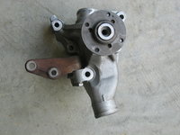


Before fitting the fan clutch bracket to the front of the engine, it's important to fit the coolant overflow reservoir to the water pump and to its lower fastener on the alternator mounting bracket. This is an NLA part from MB, which has gone NLA over the past two or three years. I was lucky to find a NOS example at a price similar to the last known price from MB. These are not available on the aftermarket. They also are not a NECESSARY part and can EASILY be eliminated / left off the car and will not cause any harm if omitted.
Here are a few views of the reservoir.


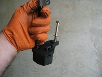
And a photo of the "weep tube" on the side of the water pump that the top of the reservoir presses onto.
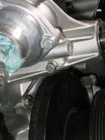
Before pressing the top of the tube onto the pump, I took my heat gun and gently warmed the top, so that it expanded and slid onto the water pump tang a little easier.


Here's where the bottom of the reservoir fastens (via a 13mm bolt) to the alternator mounting bracket.
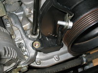


After fitting the reservoir into place, the fan clutch bracket can then be mounted. It is held to the front of the engine by four bolts, in three different lengths. All of the bolts have 13mm heads. Each bolt is torqued to 25 Nm.
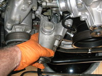

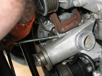


The last step is to fit the metal clip (also a single 13mm bolt) that holds the overflow reservoir's plastic line to the fan clutch bracket. In the photos below, I had it initially installed backward; the last photo shows the correct orientation. This orientation is to ensure that the line is well away from the rotating crankshaft pulley.

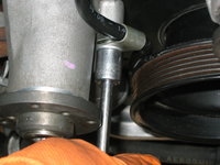


Next it was time to install the short, 90-degree hose that connects the thermostat housing to the fan clutch bracket. Pre-install the two clamps (loosely), and then wrestle the hose onto the lips. It's not too difficult, but takes a slight bit of effort.

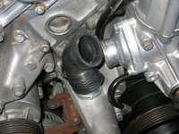
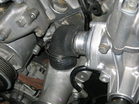

Here's the hose, installed and clamped.

And a view with the front of the engine starting to come together.
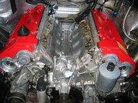
The last task for the day was to begin the installation of the distributor cap insulators, brackets and rotors. First, a final cleaning of the insulator areas with a brake cleaner-soaked rag.

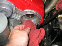
Then, break the new Bosch insulators out of my parts box.

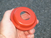

Fitting the insulators to their positions in the cylinder head covers. Then, the rotors are installed. There is a slot in each rotor that fits only one way into the end of the camshaft.
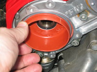


A single 5mm bolt holds each rotor bracket in place on each camshaft.


Rotor installation will continue in the next installment.
Here are a few close-up views of my "old" (original) insulators. The last two photos show a bit of oily residue stuck to the backs of the insulators, but it is NOT wet. I have never had problems with the car's running due to insulator / ignition issues.


Thanks for your interest!
Cheers,
Gerry
The first task was to re-install the fan clutch bracket, which is also part of the cooling system. Here are a few views of this bracket. The second two photos show close-ups of the modest corrosion of the aluminum inlet, which is connected by the short right-angle hose from the thermostat housing.


Before fitting the fan clutch bracket to the front of the engine, it's important to fit the coolant overflow reservoir to the water pump and to its lower fastener on the alternator mounting bracket. This is an NLA part from MB, which has gone NLA over the past two or three years. I was lucky to find a NOS example at a price similar to the last known price from MB. These are not available on the aftermarket. They also are not a NECESSARY part and can EASILY be eliminated / left off the car and will not cause any harm if omitted.
Here are a few views of the reservoir.


And a photo of the "weep tube" on the side of the water pump that the top of the reservoir presses onto.

Before pressing the top of the tube onto the pump, I took my heat gun and gently warmed the top, so that it expanded and slid onto the water pump tang a little easier.


Here's where the bottom of the reservoir fastens (via a 13mm bolt) to the alternator mounting bracket.


After fitting the reservoir into place, the fan clutch bracket can then be mounted. It is held to the front of the engine by four bolts, in three different lengths. All of the bolts have 13mm heads. Each bolt is torqued to 25 Nm.


The last step is to fit the metal clip (also a single 13mm bolt) that holds the overflow reservoir's plastic line to the fan clutch bracket. In the photos below, I had it initially installed backward; the last photo shows the correct orientation. This orientation is to ensure that the line is well away from the rotating crankshaft pulley.


Next it was time to install the short, 90-degree hose that connects the thermostat housing to the fan clutch bracket. Pre-install the two clamps (loosely), and then wrestle the hose onto the lips. It's not too difficult, but takes a slight bit of effort.


Here's the hose, installed and clamped.

And a view with the front of the engine starting to come together.

The last task for the day was to begin the installation of the distributor cap insulators, brackets and rotors. First, a final cleaning of the insulator areas with a brake cleaner-soaked rag.


Then, break the new Bosch insulators out of my parts box.


Fitting the insulators to their positions in the cylinder head covers. Then, the rotors are installed. There is a slot in each rotor that fits only one way into the end of the camshaft.


A single 5mm bolt holds each rotor bracket in place on each camshaft.


Rotor installation will continue in the next installment.
Here are a few close-up views of my "old" (original) insulators. The last two photos show a bit of oily residue stuck to the backs of the insulators, but it is NOT wet. I have never had problems with the car's running due to insulator / ignition issues.


Thanks for your interest!
Cheers,
Gerry

About 75 minutes out in the shop so far this morning. Here's what I've done during that time.
Time to install the new Beru rotors onto the brackets I mounted last night. I snugged down the 5mm center bolts that hold the rotors to the camshafts, as a first step. Then I attached both of the rotors to the brackets, via a 3mm Allen socket, 1/4" drive. MAKE SURE you have a GOOD and SOLID purchase on the rotor bolts when you are screwing them into the brackets.

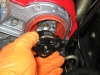
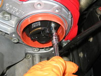

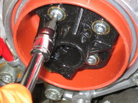

Next up, it was time to install the water pump pulley. It's a minor PITA to line up the bolts with the holes, but once you get the first and second ones started, it goes quickly. The torque for these bolts is 21 Nm. My pulley holder tool came in (as always) very handy for holding the pulley while torquing down the bolts.


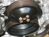


Here's the water pump pulley, installed.

The next job was to install the serpentine belt tensioner. Fortunately, as a 1994 model, I have the "later" style tensioner, which is a WHOLE LOT less fussing. Three 6mm Allen bolts hold the tensioner onto the front of the engine. The longest bolt has a sleeve that sits between the flange on the tensioner, and the front of the engine's lower timing cover. I torqued each bolt down to 21 Nm.

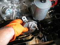


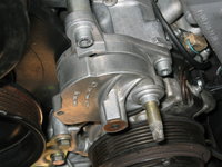

After the tensioner is installed, you install the tensioner pulley. This is held to the tensioner's shaft by a single 15mm nut, which is torqued down to 25 Nm. My pulley was missing its ornamental front cover (you can see it in the third photo below), so I had ordered a replacement back in April. Finally got to install it after the pulley was installed and torqued down, as you can see !! The cover just snaps into place.

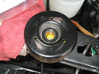


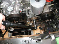


And that was it, for this installation. Going back together quickly now !!!
More soon ..... thanks for your interest.

Are your coolant expansion tank and SLS reservoir still bright-white colored?@lowman,I mean @gerryvz, what a fantastic job. Were it not for you, I would not be rushing into the garage on a Sunday morning just to check to see if my car still has its tensioner pulley ornamental cover in place (whew it does!)

A couple more hours out in the shop during the afternoon, to pick up a few more jobs.
With the insulators, brackets and rotors installed, it was time to install the new Beru caps. This I did, with the three 5mm captive Allen bolts on each cap.

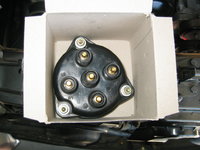
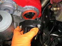

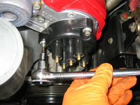
With both caps installed, I took a minute to enjoy the view of the engine compartment as it is gradually completed.


Looking at one of the old caps, I noticed something that I hadn't seen before (and which was also on the new Beru caps) — each post on the cap had a molded-in marking for "L" and "R" showing the plug wire number for that post. Wow !!!

While I was preparing to number the posts on the caps with a silver Sharpie marker, this huge fly came in and hung out for a few minutes.


Numbering the posts of each cap (mimicing the molded-in numbers, but making them more visible). This will REALLY help when it comes time to re-connect the plug wires. I also labeled each coil wire post with that side "L" or "R."


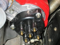
After installing and marking the caps, I bolted the alternator into position in its carrier, and installed the second shorter bolt that holds the smog pump to the carrier. Both of the bolts are 13mm.


With the alternator installed, it was time to install the LAST pulley -- the fan clutch pulley. Four bolts, each torqued to 10mm using my small torque wrench and pulley holder tool.

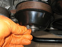

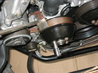
All pulleys finally installed. Looks good.
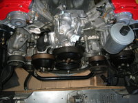
Next, on sort of a whim, I decided to change the remaining short washer line from the second washer pump to the splitter valve. The line was original, and SO fossilized hard that it had actually turned black near its connection to the washer pump.


The short hose connected to the splitter.

Then, I removed the two rubber pump grommets and both pumps. The grommets were actually in pretty good condition, but I will change them out with new ones from my parts stock.


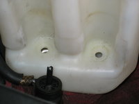
I shifted my attention to the washer reservoir itself. I siphoned out all of the washer fluid into a 1-gallon empty milk jug. Then I removed the washer level sensor, and its electrical plug. Note that the plug had a release broken off of it. This was rapidly remedied with a new pin bushing housing from my parts stock.


Replacing the pin bushing housing.


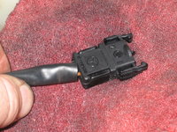
Then, I just decided to remove the entire washer fluid reservoir.....


And I'm DAMN glad I did ... because look what I found..... a LOT of rust on the bracket that holds it to the car.

A lot of work with a steel brush started to take off the rust (which was only surface rust) and the paint. I will need to finish the rust removal and then repaint the bracket.
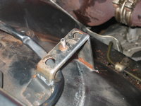
 for your interest !!
Cheers,
Gerry
With the insulators, brackets and rotors installed, it was time to install the new Beru caps. This I did, with the three 5mm captive Allen bolts on each cap.


With both caps installed, I took a minute to enjoy the view of the engine compartment as it is gradually completed.


Looking at one of the old caps, I noticed something that I hadn't seen before (and which was also on the new Beru caps) — each post on the cap had a molded-in marking for "L" and "R" showing the plug wire number for that post. Wow !!!

While I was preparing to number the posts on the caps with a silver Sharpie marker, this huge fly came in and hung out for a few minutes.


Numbering the posts of each cap (mimicing the molded-in numbers, but making them more visible). This will REALLY help when it comes time to re-connect the plug wires. I also labeled each coil wire post with that side "L" or "R."


After installing and marking the caps, I bolted the alternator into position in its carrier, and installed the second shorter bolt that holds the smog pump to the carrier. Both of the bolts are 13mm.


With the alternator installed, it was time to install the LAST pulley -- the fan clutch pulley. Four bolts, each torqued to 10mm using my small torque wrench and pulley holder tool.


All pulleys finally installed. Looks good.

Next, on sort of a whim, I decided to change the remaining short washer line from the second washer pump to the splitter valve. The line was original, and SO fossilized hard that it had actually turned black near its connection to the washer pump.


The short hose connected to the splitter.

Then, I removed the two rubber pump grommets and both pumps. The grommets were actually in pretty good condition, but I will change them out with new ones from my parts stock.


I shifted my attention to the washer reservoir itself. I siphoned out all of the washer fluid into a 1-gallon empty milk jug. Then I removed the washer level sensor, and its electrical plug. Note that the plug had a release broken off of it. This was rapidly remedied with a new pin bushing housing from my parts stock.


Replacing the pin bushing housing.


Then, I just decided to remove the entire washer fluid reservoir.....


And I'm DAMN glad I did ... because look what I found..... a LOT of rust on the bracket that holds it to the car.

A lot of work with a steel brush started to take off the rust (which was only surface rust) and the paint. I will need to finish the rust removal and then repaint the bracket.

 for your interest !!
Cheers,
Gerry
Actually they are as hard as rocks. And I have new ones already, as well as a new heater lid, cap and little cap holder piece. Everything is laying in pieces on my shop floor.Nice work, Gerry. Those grommets on the windshield washer heater lines looked a little grungy, though. Shouldn't you replace them?
Dan
Already ahead of you there !! Watch out for my next installment, where the washer reservoir gets re-done. I actually have a brand new reservoir in my parts stock -- I may use it as well.
New coolant expansion tank will be installed, as well (second time I will have done that).
Geez, my cap suddenly went missing its strap I noticed yesterday afternoon so I ordered a cap, strap and two rubber washers for both the M119 and M117 as this one I have is like shredded wheat.
It is like these things all get together and break or go missing in the same two week period across the member spectrum. I saw this, along with the broken piece (looking at a clock the section that is from about 1-4) on the PS top half of the fan shroud. Luckily I secured a primo replacement (top and bottom) the month I bought the car and it has all of its flaps and the nuts will get their due attention.
It is like these things all get together and break or go missing in the same two week period across the member spectrum. I saw this, along with the broken piece (looking at a clock the section that is from about 1-4) on the PS top half of the fan shroud. Luckily I secured a primo replacement (top and bottom) the month I bought the car and it has all of its flaps and the nuts will get their due attention.
I recommend bypassing the "captive" nuts that are in the fan shroud, and replacing them with externally accessible nuts and bolts. Makes things MUCH easier when it comes time to separate the halves. Also, use a dab of anti-seize on the threads of whatever bolts you use. The captive nuts molded into the bottom part of the shroud tend to spin in the plastic housing, and this is a SERIOUS PITA to remedy.
As for the washer reservoirs and caps, and straps -- order a couple of extras of each, particularly if you own a 126 and a 124. You will use them eventually.
As for the washer reservoirs and caps, and straps -- order a couple of extras of each, particularly if you own a 126 and a 124. You will use them eventually.
A few new items this morning, as I spent about an hour out in the shop before starting work for the day.
Picking up where I left off earlier in the week, I applied a couple of light to medium coats of Rust-Oleum spray paint, in the appropriate color, to the windshield washer fluid bracket. Still have more work to do (and perhaps a final light coat of paint), but I think it turned out nice.
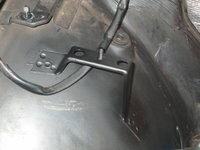

In the vein of freshening things up, I replaced the old reservoir (on the right) which was slightly yellowed, wiith a fresh new one. They are pretty cheap -- I think around $32 dollars (discounted) from MB. A few views contrasting the new and old reservoirs.


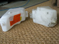
And if you're going to replace the windshield washer reservoir and the SLS reservoir, why not also replace the coolant expansion tank, as well? I had done this some years back, when I lived in Texas, but at $75 for a new tank ..... why not ?!?


For @LWB250, who immediately gravitated toward the fossilized rubber seals at the windshield washer tank heater lines in the lid, here are a couple of close-ups.


And a brand-new lid, seal, and strap recently received from MB. The second photos shows the two new grommets, as well. Just for you, LWB .....


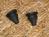
Removing the rubber grommets from the windshield washer tank lid. They certainly came out pretty easily, but you can see how fossilized they really were. The third photo shows a new grommet, next to an old one. The last photo shows the old tank lid (sans seal) and the pile of fossilized grommet parts. Into the used parts box they go.

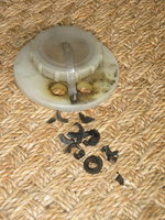
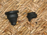
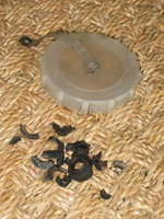
Here is the condition of the heater hose ends, before cleaning. The second photo shows the hose ends AFTER cleaning with a wire brush. It's not @lowmania level, but it's certainly good enough for me.


Next, I turned my attention to the coolant expansion tank. I removed the large circlip with my circlip pliers. This allowed me to pull out the slightly gummy old coolant level sensor. I'll keep the old tank, as it is not overly yellowed and is certainly re-usable.
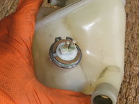


The new level sensor was made in 2014. Installation is the reverse of removal....


And a couple of views of the fully installed coolant level sensor.
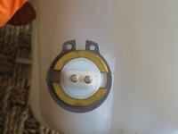

Turning attention back to the windshield washer tank, I peeled off the labels. There were three of them. The yellow label seems to indicate that the tank was temporarily on back-order, so it probably had to come from Germany.


One of the other components of the windshield washer tank was the washer fluid level sensor. I decided to re-use mine, as it was working fine. They are still available new from MB, if you need one. I used my hooked tool to remove the old rubber grommet at the top of it. The fourth photo shows the new and old grommets next to one another.


Installing the new grommet onto the washer fluid level sensor. And inserting the sensor into its hole in the new tank.
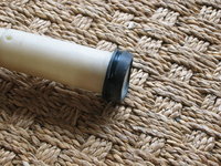


Placing a new radiator cap on the new expansion tank. I had just replaced this cap earlier in the year, so just carried it over.


On a whim, I decided to replace the black plastic cladding on the front of the cylinder head. This is the piece that goes around the cam solenoid and the distributor cap. On the driver's side, it's pretty much impossible to install (or remove) this plastic piece without cracking it (it is subjected to a lot of engine heat), and also the power steering reservoir SHOULD be removed to more easily maneuver the plastic piece. Seeing as I had recently installed the reservoir, it only took a couple of minutes to remove it again, so that I could fit the plastic piece in place. It is held to the front cylinder head cover with three 6mm Allen bolts. The bottom-most one (in the fourth photo below) is pretty much invisible down there, so it has to be installed mostly by "feel." Snug the bolts down, but don't over-tighten them. I added a drop or two of motor oil on the threads of each of the bolts, to assist them going into the cylinder head cover a bit easier.


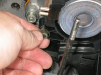
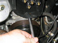
Here's what the black plastic cover looks like, installed.

Now, switch gears BACK to the windshield washer reservoir, and @LWB250's attempted shaming of me for my crumbing rubber grommets in the lid, here is the replacement of the lid, with all-new MB grommets and components. I had one or two of the large circular lids for the washer reservoir down in the basement in my deep parts stock, so I had to go and find it, which I actually quite readily did. The last few photos should help to put LWB's mind to rest, that all rubber and plastic components are new, present, and accounted for.
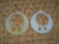

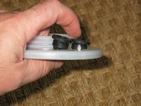
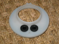


That's all for now ... more soon !!
Picking up where I left off earlier in the week, I applied a couple of light to medium coats of Rust-Oleum spray paint, in the appropriate color, to the windshield washer fluid bracket. Still have more work to do (and perhaps a final light coat of paint), but I think it turned out nice.


In the vein of freshening things up, I replaced the old reservoir (on the right) which was slightly yellowed, wiith a fresh new one. They are pretty cheap -- I think around $32 dollars (discounted) from MB. A few views contrasting the new and old reservoirs.


And if you're going to replace the windshield washer reservoir and the SLS reservoir, why not also replace the coolant expansion tank, as well? I had done this some years back, when I lived in Texas, but at $75 for a new tank ..... why not ?!?


For @LWB250, who immediately gravitated toward the fossilized rubber seals at the windshield washer tank heater lines in the lid, here are a couple of close-ups.


And a brand-new lid, seal, and strap recently received from MB. The second photos shows the two new grommets, as well. Just for you, LWB .....


Removing the rubber grommets from the windshield washer tank lid. They certainly came out pretty easily, but you can see how fossilized they really were. The third photo shows a new grommet, next to an old one. The last photo shows the old tank lid (sans seal) and the pile of fossilized grommet parts. Into the used parts box they go.


Here is the condition of the heater hose ends, before cleaning. The second photo shows the hose ends AFTER cleaning with a wire brush. It's not @lowmania level, but it's certainly good enough for me.


Next, I turned my attention to the coolant expansion tank. I removed the large circlip with my circlip pliers. This allowed me to pull out the slightly gummy old coolant level sensor. I'll keep the old tank, as it is not overly yellowed and is certainly re-usable.


The new level sensor was made in 2014. Installation is the reverse of removal....


And a couple of views of the fully installed coolant level sensor.


Turning attention back to the windshield washer tank, I peeled off the labels. There were three of them. The yellow label seems to indicate that the tank was temporarily on back-order, so it probably had to come from Germany.


One of the other components of the windshield washer tank was the washer fluid level sensor. I decided to re-use mine, as it was working fine. They are still available new from MB, if you need one. I used my hooked tool to remove the old rubber grommet at the top of it. The fourth photo shows the new and old grommets next to one another.


Installing the new grommet onto the washer fluid level sensor. And inserting the sensor into its hole in the new tank.


Placing a new radiator cap on the new expansion tank. I had just replaced this cap earlier in the year, so just carried it over.


On a whim, I decided to replace the black plastic cladding on the front of the cylinder head. This is the piece that goes around the cam solenoid and the distributor cap. On the driver's side, it's pretty much impossible to install (or remove) this plastic piece without cracking it (it is subjected to a lot of engine heat), and also the power steering reservoir SHOULD be removed to more easily maneuver the plastic piece. Seeing as I had recently installed the reservoir, it only took a couple of minutes to remove it again, so that I could fit the plastic piece in place. It is held to the front cylinder head cover with three 6mm Allen bolts. The bottom-most one (in the fourth photo below) is pretty much invisible down there, so it has to be installed mostly by "feel." Snug the bolts down, but don't over-tighten them. I added a drop or two of motor oil on the threads of each of the bolts, to assist them going into the cylinder head cover a bit easier.


Here's what the black plastic cover looks like, installed.

Now, switch gears BACK to the windshield washer reservoir, and @LWB250's attempted shaming of me for my crumbing rubber grommets in the lid, here is the replacement of the lid, with all-new MB grommets and components. I had one or two of the large circular lids for the washer reservoir down in the basement in my deep parts stock, so I had to go and find it, which I actually quite readily did. The last few photos should help to put LWB's mind to rest, that all rubber and plastic components are new, present, and accounted for.


That's all for now ... more soon !!
Last edited:
"Attempted shaming"? I think I was quite successful.

I am the king of "little rubber bits" on my cars. I have a laminated printout of the grommets page from the EPC in my garage so I can immediately identify these parts and replace them when needed.
Dan
He doesn't always post. Sometimes he's absent for years at a time. But when he DOES post, he posts zingers.Your new heat exchanger tube grommets are pressed in upside down...
And I almost hate to point it out, because this is an epic thread that just gets epic-er. This is so outstanding, Gerry. Just damn!

That'll be all of 30 seconds to remedy, seeing as I haven't inserted the heat exchanger tubes yet. I'll provide photographic evidence for you and @LWB250 !!Your new heat exchanger tube grommets are pressed in upside down...
And I almost hate to point it out, because this is an epic thread that just gets epic-er. This is so outstanding, Gerry. Just damn!
My new supply of copper washers came in from MB, so I'll be (briefly) removing this banjo bolt at the tandem pump and replacing both of the copper washers with fresh ones. This should help alleviate any leaks caused by re-using the old washers. It's OK to do this in a pinch, but best to replace the washers. They are cheap and available from aftermarket (AutohauZ) sources as well as from MB, for about 3-4x the price.Next, it was time to connect the banjo bolt fitting to the tandem pump. Unfortunately, I did not quite have the correct size of copper washer in my parts stock, so I had to re-use the original washers. I'll have to re-order a dozen or so new ones of this size. Frustrating! But I'll replace them after I receive a new stock of them.
View attachment 108628 View attachment 108629 View attachment 108630
More later today.
Those grommets on the windshield washer heater lines looked a little grungy, though. Shouldn't you replace them?
Your new heat exchanger tube grommets are pressed in upside down...
And I almost hate to point it out, because this is an epic thread that just gets epic-er. This is so outstanding, Gerry. Just damn!
These photos should get @Klink & @LWB250 off my back permanently, at least on this small topic.That'll be all of 30 seconds to remedy, seeing as I haven't inserted the heat exchanger tubes yet. I'll provide photographic evidence for you and @LWB250 !!
Question: how many of the rest of you have replaced all of the rubber items on your windshield washer tanks and lids?
Bueller —? Bueller —?
BEFORE:


DURING:
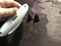
AFTER:

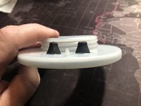

Similar threads
- Replies
- 13
- Views
- 3,305
- Replies
- 74
- Views
- 9,726
- Replies
- 129
- Views
- 9,653
- Replies
- 192
- Views
- 17,473
- Replies
- 26
- Views
- 2,530
Similar threads
- Replies
- 13
- Views
- 3,305
- Replies
- 129
- Views
- 9,653

