• Hi Guest !

    Welcome to the 500Eboard forum.

    Since its founding in late 2008, 500Eboard has become the leading resource on the Internet for all things related to the Mercedes-Benz 500E and E500. In recent years, we have also expanded to include the 400E and E420 models, which are directly related to the 500E/E500.

    We invite you to browse and take advantage of the information and resources here on the site. If you find helpful information, please register for full membership, and you'll find even more resources available. Feel free to ask questions, and make liberal use of the "Search" function to find answers.

    We hope you will become an active contributor to the community!

    Sincerely,
    500Eboard Management

RESTO PROJECT: M119 / W124 / E500 Engine Top-End Refresh

I have on the SEC, but have not had a need just yet for my E500. I have spare grommets for them and the cap and strap and washer arrive Friday.
You should probably use those grommets soon and get the proper life out of them, because rubber degrades and disintegrates before your eyes in the hot, humid weather of south-central Texas. Particularly when you don't have a nice cool, climate controlled basement to store your parts. Ask me how I know ... :duck:
 
Your new heat exchanger tube grommets are pressed in upside down...
And I almost hate to point it out, because this is an epic thread that just gets epic-er. This is so outstanding, Gerry. Just damn!

Hi Klink,

Where have you been hanging out?

Havn't seen you much lately. We miss you here. :runexe:

lol
 
You should probably use those grommets soon and get the proper life out of them, because rubber degrades and disintegrates before your eyes in the hot, humid weather of south-central Texas. Particularly when you don't have a nice cool, climate controlled basement to store your parts. Ask me how I know ... :duck:

I have consumable parts like that (not liquids) stored inside at the office storage. Long term NLA stuff and electrical bits stored in climate controlled storage unit.
 
Today I spent about 2.5 hours out in the garage (and about an hour later yesterday), and continued on with a few tasks that I'd previously started. Here's an overview of what I did.

First, I attached the other black plastic cover on the front of the right (passenger) side cylinder head. Same process -- three 6mm Allen bolts, and a drop of motor oil on each bolt's threads to help ease it home.
IMG_0670.JPG IMG_0671.JPG IMG_0672.JPG IMG_0673.JPG


Here's the engine with the covers installed. Looking mo' betta all the time !!
IMG_0674.JPG


Next it was time to take care of the two vacuum switchover valves and their brittle and broken vacuum tubing, on the passenger side inner fender area. Here are a few shots of how things looked as I found them. You can see a zip-tie that looks decidedly NON-factory, attaching the bundle of three vacuum lines to the bottom of the bracket that the windshield washer container fits into.
IMG_0675.JPG IMG_0676.JPG IMG_0677.JPG IMG_0678.JPG


Each of the two switchover valves is held to the firewall by two 8mm sheet metal screws -- despatched easily enough.
IMG_0679.JPG IMG_0680.JPG


And once removed, here is what the bundle of vacuum lines and attached valves looked like. Close-ups are a good reference for re-assembly.
IMG_0681.JPG IMG_0682.JPG IMG_0683.JPG IMG_0684.JPG


I removed everything from the two valves, and using some cleaner and a toothbrush, I cleaned them off a bit. Not perfect, but also no longer grimy.
IMG_0685.JPG


Bringing all of the vacuum lines into the house, I spread everything out on to the kitchen table. I measured all of the original vacuum lines and cut new lengths to replace them, as well as installing new rubber vacuum connector ends. Everything was re-sheathed in a new length of fiberglass Hot Rod Sleeve, which replaces the heat and age-brittled factory black plastic sheathing.
IMG_0686.JPG IMG_0687.JPG


This short length of tube sticks out of the middle of the Hot Rod Sleeve, and attaches to the smog pump valve as the bundle of vacuum lines passes by the area on the way up to the intake manifold.
IMG_0688.JPG


The next task was to replace the two copper washers I'd re-used at the banjo bolt connection at the tandem pump. A quick removal of the banjo fitting with a 17mm wrench, and exchange of the old copper washers with the new ones, made short work of this job.
IMG_0689.JPG IMG_0690.JPG


New copper washers as received from MB. The second photo shows the old washers (top two) and the new ones (bottom two).
IMG_0691.JPG IMG_0692.JPG


Threading the new washers on, and then re-installing the banjo fitting onto the tandem pump.
IMG_0693.JPG IMG_0694.JPG


I returned to the switchover valves, and installed them with their 8mm screws.
IMG_0695.JPG IMG_0696.JPG IMG_0697.JPG


After that, I installed the new coolant expansion tank. A little light coating of synthetic grease helped ease the bottom "foot" of the expansion tank through the new rubber grommet I'd previously installed in the wheelhouse.
IMG_0698.JPG IMG_0699.JPG IMG_0700.JPG


Turning now to the @Klink and @LWB250 windshield washer tank lid, I slowly installed the two heater pipes through the now correctly-installed rubber grommets pressed into the tank. Again, a light coating of synthetic grease applied with a Q-tip helped the pipes slide through the very tight grommets.
IMG_0701.JPG IMG_0702.JPG IMG_0703.JPG IMG_0704.JPG IMG_0705.JPG IMG_0706.JPG IMG_0707.JPG


I carefully pressed the lid onto the top of the new tank, and everything turned out quite nice! Hopefully, @Klink and @LWB250 approved.
IMG_0708.JPG IMG_0709.JPG IMG_0710.JPG


The final step was to install two new rubber grommets for the windshield washer pumps. My parts stock had a stash of 6-7 of them, so this was easy enough to "raid." You can see in the second photo the enlarged holes in the old grommets (top pair) vs. a fresh pair. Even though these grommets were not leaking and still quite usable, I changed them as a matter of course.
IMG_0711.JPG IMG_0712.JPG IMG_0713.JPG IMG_0714.JPG


Then it was time to install the washer reservoir onto the fender well. It, too has a "foot" that fits into a bracket with a rubber liner in it.
IMG_0715.JPG


For the other side, with the previously surface-rusted bracket, I took a 1" x 3" cutting from an old bicycle tube, and punched a hole through it for the center bolt. This hopefully will provide some cushioning and insulation between the washer reservoir and the bracket itself. Props to @nocfn (@281lxm) for the idea).
IMG_0716.JPG


Replaced the pin bushing housing for the wires for the coolant level sensor with a new plastic housing. Just because....
IMG_0717.JPG


Then it was time to tighten down the two 10mm nuts that hold the expansion tank to the fenderwell, and route the windshield washer heater lines under the edge of the expansion tank.
IMG_0718.JPG IMG_0719.JPG IMG_0720.JPG


Finishing touch was to press the hose onto the fitting. This is the hose that leads to the coolant overflow tank behind the fender.
IMG_0721.JPG


Test-fitting the windshield washer reservoir into place. Everything lines up and looks good....
IMG_0723.JPG IMG_0724.JPG


Then it's time to install the two rubber hoses that attach to the washer reservoir heater coil inside the tank.
IMG_0725.JPG IMG_0726.JPG


Clamp 'em down and we're all done. Everything looking good....except two final tasks....
IMG_0727.JPG IMG_0728.JPG


Installing the screw that holds the washer tank to the fenderwell, and installing the second, freshly-bushed washer fluid level sensor connector to the sensor.
IMG_0729.JPG IMG_0730.JPG IMG_0731.JPG

That's about all for today. Next up will be the completion of the vacuum connections at the switchover valves, and then the re-installation of the headlight and plastic headlight air scoop. That should button things up in that area.

:thankyou: for your interest! More soon.
 
These photos should get @Klink & @LWB250 off my back permanently, at least on this small topic.

Question: how many of the rest of you have replaced all of the rubber items on your windshield washer tanks and lids?

Bueller —? Bueller —?

I did this a few months ago, but I'm afraid I installed mine upside down too. I'll have to check when I get home.
 
Don’t post photos whatever you do Jon ! You can live vicariously through my incorrect install and subsequent chastisement ;-)

At least they didnt mention the valve stem oil seals which form a large part of deferred maintenance cost which only a few members counted on one had can say they replaced :choochoo:

For the naysayers and for avoidance of doubt - you know all that hard rubber parts up top? Hard like stone yes?

Well what state do you think the valve stem oil seals are in!? They are exposed to extreme heat and motor oil and moving valves. At 30 years old they are toast. Done. Shot.

"But I dont see blue smoke- this is not required!!" Good luck with that theory. If in the engine deep then it is not much more work to remove head bolts and exhaust manifolds and get the heads checked, cleaned, valve job and renew the valve stem oil seals for another 30 years of service :) Fresh head gaskets certainly won't hurt either. Indeed I still have my old ones and can show deterioration.

Otherwise without replacing valve stem oil seals you are on borrowed time and simply awaiting the blue smoke to start.

Example- my 500E does have blue oil smoke on cold startup after a couple of days. So when I do a refresh on that engine it will absolutely include valve stem oil seals.

Rant over

This is intended to simply suggest that if you are In this far do consider the valve stem oil Seals early on. I know that this can be a controversial subject on the board as some members vehemently deny the need to renew them but.....

20190801_215010.jpg

These were hard as plastic and crumbling on removal. There was also a visible gap between the old seal and the valve stems.

Your engine is looking great now Gerry! Nice job
 
Last edited:
Gerry - the bike tube was a good source of thin rubber that will last the ages. My wonderment was how did water get there to rust in the first place. Well the answer is the flower bolt to hold it down. It is hollow from top to bottom, over spill falls in the tube design and sits on top of the bolt welded into the frame. I took an old piece of vacuum hose, cut it small enough to push it in and compress the hole tightly to fill the hole. Fluid will sit in the top of the flower for easy cleanup, or just evaporate rather then stay in the tube plugged at the bottom by a rusting bolt.
 
I'm sort of thinking that I should pull the heads now, and have all of the valve seats reground, new valve guides pressed in, and new valve stem seals done. Test all of the lifters. Probably best to do it now while things are apart !!

Best yet, perhaps just buy a showroom-miles car if I can find one.
 
Gerry - the bike tube was a good source of thin rubber that will last the ages. My wonderment was how did water get there to rust in the first place. Well the answer is the flower bolt to hold it down. It is hollow from top to bottom, over spill falls in the tube design and sits on top of the bolt welded into the frame. I took an old piece of vacuum hose, cut it small enough to push it in and compress the hole tightly to fill the hole. Fluid will sit in the top of the flower for easy cleanup, or just evaporate rather then stay in the tube plugged at the bottom by a rusting bolt.
It wouldn't be too big of a deal to just replace the flower bolt with a standard M6 bolt with a fat washer to press against the washer flange. I'm contemplating doing that right now, actually.
 
I'm sort of thinking that I should pull the heads now, and have all of the valve seats reground, new valve guides pressed in, and new valve stem seals done. Test all of the lifters. Probably best to do it now while things are apart !!

Best yet, perhaps just buy a showroom-miles car if I can find one.

While you're in there, I think you should pull and inspect the pistons, conrods and replace the bearings too. Maybe look at getting a new crank.
 
I'm sort of thinking that I should pull the heads now, and have all of the valve seats reground, new valve guides pressed in, and new valve stem seals done. Test all of the lifters. Probably best to do it now while things are apart !!

Best yet, perhaps just buy a showroom-miles car if I can find one.
While you're in there, I think you should pull and inspect the pistons, conrods and replace the bearings too. Maybe look at getting a new crank.

You can bring a horse to water but you cant make him drink

:pc1:
 
That doesn't go far enouh. While everything is apart ..... send the block off and get it bored out, and order new 6L pistons and a stroker crank! Because, @JC220.
You have nitrous? You'll never know if one of these is lurking just below the deck.
 

Attachments

  • Tucson-20161011-00479.jpg
    Tucson-20161011-00479.jpg
    2.1 MB · Views: 26
I'm sort of thinking that I should pull the heads now, and have all of the valve seats reground, new valve guides pressed in, and new valve stem seals done. Test all of the lifters. Probably best to do it now while things are apart !!

Best yet, perhaps just buy a showroom-miles car if I can find one.

I suspect this will fall on deaf ears and that is fair enough I respect everyone's opinion.

In short - the following elements of work:

Machine shop:
Heads ultrasonic cleaned
All valve guides checked for wear-AOK.
Head checked for flatness- AOK
Walnut blast valves to remove carbon
All valve seats checked. Issues found but a lap brought them all back.
Test all valves with engineers dye and vacuum tester - all passed after.
Check valve springs (load tests)
Assembly of valves and oil seals in heads so I got the heads back sealed in bags and ready to drop onto block.

20190819_210750.jpg20191102_184717.jpg20191102_182027.jpg

Approx £150 gbp for above. Admittedly they treat me right since I have been going there for years with MB stuff.

I de-carbonised the pistons as a bonus whilst in there and inspected all bores = great.

20190824_152450.jpg20190824_165811.jpg

New Head Gaskets (Genuine MB only - nothing else!!) +£120 or so.

20191106_203044.jpg

Checked head bolts per WIS, all good and in spec - reuse.

Extra cost in my time - about a days labour. Peace of mind- in particular the old hard as nails valve stem oil seals being replaced- priceless.

This m119 in my S500 is good for 20+ years IMO without being opened again. Hopefully!

Will valve stem oil seals if not currently leaking per say (but they will be f#cked I assure you folks) last another 20 more years? (40 years in service?)

Just saying it depends on your long term goals. But it's not really a huge deal to do these extra steps and it would be a damn shame to have to go all the way back in there again a couple years later and waste all the other new gaskets.
 
@Glen ... How many times has your high-miler had this done in its 750Kmi life? Three? Four?

I'm sure that the @gsxr, with all of his M119s, gets a multiple-engine discount on this work from his local MB friendly machine shop?
 
@Glen ... How many times has your high-miler had this done in its 750Kmi life? Three? Four?

I'm sure that the @gsxr, with all of his M119s, gets a multiple-engine discount on this work from his local MB friendly machine shop?

Heads have never been off in ~646K miles (1.04 Mkm). Valve stem seals definitely need to be done though...going through a quart of oil every 800 miles these days but it still easily passes California emissions tests so I haven't been motivated to do them.
 
Heads have never been off in ~646K miles (1.04 Mkm). Valve stem seals definitely need to be done though...going through a quart of oil every 800 miles these days but it still easily passes California emissions tests so I haven't been motivated to do them.

Hmmm I would be loathe take the heads off
the high miler at this stage!

The risk is, if you find something else like bore wear then is It really worth fixing? Given it is a high miler and most of the fun I bet is knowing the engine is original and heads never off too....

You can renew the Valve Stem Oil seals with the heads on but the motor has to come out to do so. Not enough room to do in situ.
 
Last edited:
This thread has gotten way off track, so let's get it back on. About an hour out in the shop late this morning (in between JC's recommendations to proactively tear the entire top of the engine off and rebuild it from scratch) resulted in the following:

Fitment of the main washer fluid pump into the new grommet in the base of the washer reservoir.
IMG_0733.JPG IMG_0734.JPG IMG_0735.JPG IMG_0736.JPG


Fitment of the vacuum lines on the passenger side of the engine. The earlier photos and the engine vacuum diagram came in very handy for doing this.
IMG_0732.JPG IMG_0737.JPG IMG_0738.JPG


Here are what things look like when completed at the inner fender-well.
IMG_0739.JPG


I marked the other end of the appropriate vacuum line with "EGR," as it will be attaching to the EGR valve once I fit the intake manifold in place.
IMG_0740.JPG


And then I fitted the short tube to the smog pump valve, with a new length of rubber vacuum hose between the end of the vacuum line and the valve's metal nipple.
IMG_0741.JPG IMG_0742.JPG IMG_0743.JPG


Next, with the lines in place, it was time to start cinching things down in the factory locations. I broke out my MB zip tie bag, and snagged and then installed a zip tie to hold the vacuum lines down at the base of the washer reservoir foot.
IMG_0744.JPG IMG_0745.JPG IMG_0746.JPG


Then I connected the smog pump to its connector just to the rear of the headlight. Then routed the smog pump cable in the factory location.
IMG_0747.JPG IMG_0748.JPG


Then I routed the bundle of vacuum lines between the smog pump and the alternator, in the factory routing.
IMG_0749.JPG


Then it was time to install the plastic headlight bucket, and route the headlight wiring through it.
IMG_0750.JPG IMG_0751.JPG IMG_0752.JPG


Then, fit the NLA "finger foam" into its place in the corner behind the bumper.
IMG_0753.JPG IMG_0754.JPG


Last step for now was to fasten the plastic headlight bucket to the front end of the car with the four small 8mm screws.
IMG_0755.JPG IMG_0756.JPG IMG_0757.JPG

More to come soon....
 
This thread has gotten way off track, so let's get it back on. About an hour out in the shop late this morning (in between JC's recommendations to proactively tear the entire top of the engine off and rebuild it from scratch) resulted in the following:

Fitment of the main washer fluid pump into the new grommet in the base of the washer reservoir.
View attachment 110732 View attachment 110733 View attachment 110734 View attachment 110735


Fitment of the vacuum lines on the passenger side of the engine. The earlier photos and the engine vacuum diagram came in very handy for doing this.
View attachment 110731 View attachment 110736 View attachment 110737


Here are what things look like when completed at the inner fender-well.
View attachment 110738


I marked the other end of the appropriate vacuum line with "EGR," as it will be attaching to the EGR valve once I fit the intake manifold in place.
View attachment 110739


And then I fitted the short tube to the smog pump valve, with a new length of rubber vacuum hose between the end of the vacuum line and the valve's metal nipple.
View attachment 110740 View attachment 110741 View attachment 110742


Next, with the lines in place, it was time to start cinching things down in the factory locations. I broke out my MB zip tie bag, and snagged and then installed a zip tie to hold the vacuum lines down at the base of the washer reservoir foot.
View attachment 110743 View attachment 110744 View attachment 110745


Then I connected the smog pump to its connector just to the rear of the headlight. Then routed the smog pump cable in the factory location.
View attachment 110746 View attachment 110747


Then I routed the bundle of vacuum lines between the smog pump and the alternator, in the factory routing.
View attachment 110748


Then it was time to install the plastic headlight bucket, and route the headlight wiring through it.
View attachment 110749 View attachment 110750 View attachment 110751


Then, fit the NLA "finger foam" into its place in the corner behind the bumper.
View attachment 110752 View attachment 110753


Last step for now was to fasten the plastic headlight bucket to the front end of the car with the four small 8mm screws.
View attachment 110754 View attachment 110755 View attachment 110756

More to come soon....

Not intending to call out your project at all @gerryvz this is another epic thread and I am following it with interest as I am sure others are!

Keep up the great work and I hope to follow suit all over again with my 500E this winter :choochoo:
 
A couple more shots of a few things, about an hour out in the shop around dinner time.

First, and I didn't take any photos of it, I replaced all of the lower cladding (underneath the fog lights in the front spoiler), and in the wheelhouses on either side. Each side had about four or five 10mm plastic nuts and metal screws that I had to replace under the car and in the wheel wells to cinch down.

After that was done, I could FINALLY (after about 2.5 months of one side up in the air) lower the car back down onto its own four wheels. This was in anticipation of torquing the center crankshaft bolt to its 400 Nm of specified torque.
IMG_0758.JPG


I brought out the 3/4" drive torque wrench I'd bought some time back, as well as the 27mm impact-rated socket, to begin this job. I quickly realized that I will need a "breaker" bar that is large enough in diameter to fit around the 1.5-inch diameter of the torque wrench handle. I think I have a piece of metal pipe in my basement that I can cut down to a 4-5 foot length, to use as this breaker bar.
IMG_0761.JPG IMG_0763.JPG IMG_0765.JPG


The last thing I did for the night, before coming into the house, was to break out the plastic piece that fits on the front of the inside firewall, directly behind the engine. I had removed this piece to get at the windshield wiper and water drain setup when I pulled it to clean things up and refurbish everything.

This plastic piece is held on by two large metal bolts, and a 10mm plastic nut on the passenger side. I began installing it but didn't completely finish. I will finish the job today and make sure everything is in place.
IMG_0766.JPG IMG_0767.JPG IMG_0768.JPG IMG_0769.JPG
 
About 90 minutes in the shop this morning, working on a few various and sundry tasks. Here's an update.

The first thing I did was to finish installing the center plastic piece that I'd started last night, which goes on the firewall just in front of the rain water & windshield wiper assembly. I had to install the 10mm plastic nut on the driver's side of the plastic, which threaded onto a threaded stud that came out of the firewall. Unfortunately I found that the threaded nut ended up being stripped. But ... I had a large stash of brand-new nuts right at hand, so I was able to install a new one, which threaded up and tightened just fine.

That little job was done.

Now, on to the center crankshaft bolt, which (as mentioned ) has a torque specification of 400 Nm. The factory service manual says that you need to oil the threads of the crank bolt and the four concave dished washers, so I added a drop onto the threads and in between the washers with my handy oilcan.
IMG_0770.JPG IMG_0771.JPG IMG_0772.JPG IMG_0773.JPG


Next, I threaded the bolt into the end of the crankshaft, and gave it a few turns with the 3/4" torque wrench. You can see this process in the photos below.
IMG_0774.JPG IMG_0775.JPG


Then came the time to torque the bolt down to its 400Nm (~300 lb-ft) spec. I was agonizing about what I would do for a lever, because the diameter of the torque wrench was just over 1.5", and I didn't have a piece of pipe (nor my jack's tubular metal handle) of appropriate diameter to fit over the wrench's handle. Home Depot and Lowe's didn't have anything that would readily work, either.

So, I scratched my brain all night, and woke up this morning and remembered that when I had moved into my new house in Annapolis almost three years ago, the builders had left a 1.75" piece of pipe about five feet long out in a drainage culvert on my property line, near the street. Some months later I had grabbed this pipe and put it on the side of my house, near the outside stairs leading down to the outside basement entrance.

:kapow:

It worked perfectly as a lever, and the torque wrench with lever made very very short work of the torque for the crank bolt. Job done.
IMG_0776.JPG IMG_0777.JPG


Then it was time to turn my efforts to installing the right (passenger) side headlight. Process was pretty much the same as the driver's side.
IMG_0778.JPG IMG_0779.JPG IMG_0780.JPG IMG_0781.JPG IMG_0782.JPG IMG_0783.JPG IMG_0784.JPG IMG_0785.JPG


Installing the headlight washer and wiper...
IMG_0786.JPG IMG_0787.JPG IMG_0788.JPG


And, my car after a couple of months, has both of its "eyes" back. :wahoo:
IMG_0789.JPG

More later. Going to the Maryland Eastern Shore for the afternoon and for dinner.


A preview of the next few jobs I'll be doing:
  • Re-lifting the car
  • Removing the flywheel lock (now that the crank bolt has been torqued down)
  • Replacing the flywheel lock cover
  • Replacing the exhaust crossover pipe
  • Installing the fan and new MB/Horton fan clutch
  • Installing the new Behr radiator
  • Finishing cleaning the cylinder head intake area and vacuuming out the intake valve areas
  • Installing the intake manifold assembly
  • Installing the fuel rail and fuel injectors
  • Pouring in new fluids: coolant; transmission fluid; SLS fluid; power steering fluid
 
Last edited:
GVZ get some waterless evaporator coil cleaner, spray it on the condenser since you have such access, both sides - empty the aerosol can. Let it soak, evaporate and if you have air, blow it clean and dry. Great time to do it.
 
That’s a great call. I shall do that as one of my next tasks. I can use my shop air to blow the condenser out from behind.
 
Little bit of stuff, ongoing..... as promised. About 30 mins out in the shop, so far.

My replacement VDO washer pump, for the headlight wipers, arrived, so I installed it. It's white, but recent production. It's VDO/Hella, same as the factory pumps, but at one-half the price. I wrote the date on it so that I can see at a glance when it was replaced.
IMG_0790.JPG IMG_0791.JPG IMG_0793.JPG


Next up, I decided to start working on the clean-up of the intake area, and the tops of the intake valves, stems, and so forth. I had started one side of the car in the early stages of the project, but abandoned the cleanup when I started removing more parts off of the car. Of course, this has to be done before I install the intake manifold assembly.

To clean the intake manifold seating area on the cylinder heads, I am using (carefully) a razor blade as a scraper, and Scotch Brite pads and rags soaked in brake cleaner to remove surface dirt. For the intake valve area, I am using Q-tips and cotton swabs on long sticks, all soaked in brake cleaner, to get down into the chambers and remove large dirt and dust particles. After I am done, and immediately prior to intake manifold assembly, I will vacuum out the area with my shop vac and a thin tube. This should remove any dirt and debris that has gotten down in there.

After I clean every port out, I am taping it off temporarily so that no more crud gets in while I am cleaning the other ports. The other side of the engine is blocked off while I am cleaning one side. Sort of a PITA, but cleanliness is important here. It's slow and tedious work, but it has to be done.

Here are a couple of views of things....
IMG_0794.JPG IMG_0795.JPG


Lastly, for now, I promised a long time ago a comparison between the Nissens radiator (made in Denmark) and the new Behr radiator (made in South Africa) that I'd ordered. The Nissens was a relatively new unit, and was cooling fine and not leaking, but when I was removing the lower transmission line from its connection on the bottom of the passenger side, the metal surround under the bolt started spinning, and stripped out. I don't know for sure, but I think this would have resulted in a leak of transmission fluid had I re-used and reconneected the transmission cooler line to it.

So, I decided to just buy a new Behr unit. It arrived nicely packed, and I've had it sitting upright next to the wall in my shop since I received it.

Here are some comparisons between the Nissens and the Behr radiators.

First, an overview of the Nissens (left) and Behr (right) units, overall. Look pretty similar.
IMG_0796.JPG IMG_0800.JPG


It doesn't take long before the differences start becoming apparent, though. You can see that the Nissens (left, below) radiator upper hose neck is NOT reinforced. The Behr neck (right, below) has a metal reinforcing piece in it. This is a big plus for the Behr, for long-term longevity of the radiator neck under repeated heat cycles.
IMG_0797.JPG IMG_0801.JPG


The next thing you see is a difference in the design of the transmission cooling line connector. With the Nissens unit (left, below), you see the nut is resting on a plastic base. The Behr unit (right, below) has a beefier, netal base underneath the transmission line connecter. This is exactly the connection that stripped out on the Nissens radiator, because the connector nut started rotating on top of that plastic round base, and this is a leak point that essentially rendered the radiator unusable.
IMG_0798.JPG IMG_0802.JPG


Next up, you see the bottom connection where one of the two clamps that hold the transmission line attach to the bottom of the radiator. On the Nissens unit (left, below), I actually had to the take the "L"-shaped angle bracket off of the preceding Behr unit that it replaced, and fabricate a bracket for the clamp. Actually, I did this for both left and right sides on the Nissens radiator. The Behr unit (right, below), comes with both of the brackets ready to go, attached, and no further work is required to attach the two clamps.
IMG_0799.JPG IMG_0803.JPG


Moving forward, I just show you a shot of the actual lower transmission line connection that stripped out and rotated, on the Nissens radiator (left, below). And a close-up shot of the same connector on the Behr unit (right, below).
IMG_0805.JPG IMG_0806.JPG

And lastly, a close-up shot of the labels on the top of both of the radiators. Behr on top, Nissens underneath.
IMG_0804.JPG

I had no issues whatsoever with the Nissens radiator, and I do believe (at least the Danish-made units) are of good quality. HOWEVER, I believe they do cut a few corners as compared to the Behr units -- in terms of not having a reinforced hose neck; not having the hose clamp brackets at the bottom, and the transmission cooler line connections perhaps not being as stout as they could be.

If you were to be in the market for a radiator, and the Nissens and the Behr were around the same price, I would definitely opt for the Behr unit. However, if the Nissens unit (assuming it is as well made as they used to be) was substantially less expensive, I would opt for that unit.

Hope this helps.

Cheers,
Gerry
 
Gerry, what vendor did you source the SA-built Behr from? FCP doesn't appear to carry it.

AHAZ has a Mahle-Behr for only $119 which makes me think China, not South Africa...


:duck:
 
Gerry, what vendor did you source the SA-built Behr from? FCP doesn't appear to carry it.

AHAZ has a Mahle-Behr for only $119 which makes me think China, not South Africa...


:duck:


I saw that! So odd! I bought a Behr radiator from AHAZ in 2016 (Not Mahle-Behr) and it was twice the price:

1597720066974.png
 
Yeah, AutohauZ is the only place I've seen such a cheap Behr unit, which is half the price of Behrs anywhere else. It's cheap enough that I do believe it is part of a "Chinese" made line of products, because the longstanding Behr radiators of good quality have been made in South Africa forever. I was not willing to take a chance on it, to be honest.

RM Yurropean had essentially the best price on the "real" Behr units, and good shipping and sales tax policies. AutohauZ has in recent months revoked their free shipping over $75 policy, and started collecting sales tax, making them less attractive more of the time, unless (which does happen on occasion) their prices are significantly better than RM Yurropean (or for some, FCP Yurro).
 
My dad's e420 cracked the top neck of his OE Behr. I bought him a Nissens, and he installed it with no modifications at all, it was drop in and new crush washers. (new rubber kit of course)
 
Took a break from work, and spent about an hour out in the shop preparing the intake valves and surface on the top of the cylinder heads for mounting of the intake manifold assembly. I'm about 60% done with the job.

What I have been doing is uncovering a pair of intake valves at a time, and cleaning the dust and debris that I can off of the tops of the valves, and cleaning the sealing surface of the cylinder head for the intake manifold gaskets. Tools used are sharp razor blades for scraping dirt off (carefully), and then scraping the top of the cylinder heads, and Q-tips and cotton swabs on long wooden sticks — soaked in brake cleaner — to clean the coolant and air passages on the intake manifold itself. Each pair takes about 20-25 minutes to do a good job.

After cleaning a pair of valves and their surrounding area, I re-cover them with new strips of ductape to keep out any further dust and dirt. Immediately before I install the intake manifold and gaskets, I will use my shop vac to vacuum out everything, and also possibly an air-gun in combination with it.

Here is some progressive work I've done...
IMG_0809.JPG IMG_0810.JPG IMG_0811.JPG IMG_0812.JPG IMG_0813.JPG IMG_0814.JPG


I'll post the finale of this process as I get it completed.
 
A few more shots as I spent about an hour out in the garage this morning. Goal was to finish up the first-round cleaning of the cylinder head intake area. And to install a few newly received parts.

First, I wanted to turn my attention to the windshield washer reservoir. I sort of felt that I hadn't completed the job, so I did so with the addition of a new nut, a new cap, and a new washer level sensor.
IMG_0815.JPG IMG_0816.JPG IMG_0817.JPG IMG_0818.JPG


Note that the washer level sensor part number has been superseded to a 140 part number, which is significantly deeper than the old one. Wanted folks to see this. It does still work in the application, though. But because it is deeper, it means that you will be filling up your washer tank more frequently. The "stock" MB part number for the original washer level sensor was 129 540 02 17. The "new" superseded part number is 140 540 00 17.
IMG_0819.JPGIMG_0820.JPGIMG_0821.JPGIMG_0822.JPG


After that, I replaced one of the small plastic clips that clip the two coil wires together after they leave the plastic coil housing caps. I ordered four of these small clips, but only one was needed. I also replaced one of the caps, because I didn't like the condition/look of one of the original caps. They are cheap and still available. I ordered a second coil cap as a spare for my 560SEC, which uses the same part.
IMG_0823.JPG IMG_0825.JPG IMG_0826.JPG


Then I turned my attention to finishing off the cleaning of the cylinder head and intake valve areas on the left (driver's) side, which I'd started yesterday. Every thing cleaned up pretty nicely, and is ready externally for the installation of the intake manifold and gaskets. I still need to get my shop vacuum and simultaneously blast out each intake valve area with blasts of compressed air. Hopefully that will blow some additional carbon and crud free and suck it up at the same time.
IMG_0827.JPG


I got out the new set of Elring intake manifold gaskets that I'd ordered back in April.
IMG_0828.JPG


And pulled out the intake manifold from storage in the garage, which I'd cleaned and re-assembled several months ago. One thing I did — a lesson learned from my 560SEC top-end rebuild some 10 years ago — was to check the integrity of ALL of the rubber donut rings that connect the upper and lower halves of the intake manifold. With the SEC, I had mis-assembled one of the rings, and it was not fully sealed where the two manifold halves mated. This resulted in a vacuum leak that took me some effort to track down.

This time around, I used a light and mirror to check the back-side and front-side of EACH of the eight donut rings. Everything looked to be nicely sealed up. I then double-checked it again.
IMG_0829.JPG IMG_0830.JPG

And that was it for my hour out in the shop. More to come. The intake manifold install will be one of the next major jobs that you will see, after I finish cleaning things out.
 
About three or four hours in the shop over the past couple of days, as I am definitely starting to see light at the end of the tunnel.

First, I took a look at my handiwork after completing the headlight install, along with the washer reservoir, and the associated vacuum plumbing to the switchover valves in the area. It was very satisfying to see that everything had been done and refurbished in this area. I actually removed the washer fluid reservoir again, and replaced the small rubber foot that held the forward end of it into the small bracket. It was a small thing, but seeing I had vowed to replace everything rubber in the engine compartment..... and it came in a very timely manner in my latest parts order (took only two days to get it).
IMG_0833.jpeg


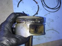
After that, it was time to break out my shop air compressor to take care of a couple of clean-up jobs — mainly blowing out the intake valve areas on each cylinder, and also to blow out the spark plug holes for replacement of the spark plugs. I had not replaced the spark plugs since early 2009, not long after I moved to Texas.

So, I broke out my skinny nozzle for the end of my air compressor's hose, and attached it. Then I went to work blowing out each cylinder's intake valves. Blowing them out REALLY made a big difference and got a lot more stuff out than I had done (or could do) manually, despite spending a couple of hours trying to do so. I did one pair of valves at a time, and then covered them back up so that no additional removed dirt and crud got back into them.
IMG_0836.jpeg IMG_0837.jpeg


Then I blew out each spark plug hole.
IMG_0834.jpeg IMG_0835.jpeg


Broke out a brand-new box of vintage Bosch (made in Gemany) MB F8DC4 plugs from my parts stash.
IMG_0831.jpeg IMG_0832.jpeg


And using my special swivel "GearWrech" 3/8" magnetic socket adapter, obtained a while back from Amazon, I replaced each spark plug. Torque for each plug is 28 Nm. I did NOT put any anti-seize paste on the threads of each plug.
IMG_0838.jpeg IMG_0839.jpeg IMG_0840.jpeg IMG_0841.jpeg


And broke out the new, fresh plugs. Gap for each new plug is 1.0mm, or (English system) 0.0395 inch (I used 0.040 inch as indicated on the gapper).
IMG_0842.jpeg IMG_0843.jpeg


And....installing each plug, one by one.
IMG_0844.jpeg IMG_0845.jpeg


Next, it was time to turn my attention installing the intake manifold to the cylinder heads. Before I did this, I laid out all of the intake manifold bolts, as shown below. There are three lengths of bolts -- two LONG ones, four medium ones, and eight shorter ones. And a bracket, which goes onto one of the medium bolts.

As a rule of thumb, the bolt pattern is as follows:
  1. The two long bolts go in the front-most, inner positions on the intake manifold.
  2. The four medium bolts go in the four rear-most (inner and outer) bolts closest to the firewall. The medium bolt with the bracket goes in the inside rear position on the driver's side (I'll show this later in a photograph).
  3. The eight short bolts go in along the inside sides of the intake manifold.
IMG_0846.jpeg


Before test-fitting the manifold into place, I needed to do a few steps first. First, I removed all of the duct-tape that I had used to cover the intake and coolant ports. It's important to remove any left-over adhesive junk from the tape on the gasket sealing surface. I cleaned the gasket sealing surface by lightly wiping it with a towel soaked in brake cleaner. This served as a "final clean" before test-fitting the manifold in place. I then also did a visual check to make sure everything was out of the way at the back of the engine (accelerator linkage, and so forth.
IMG_0847.jpeg


The first photo below shows what things looked like before I removed the new Elring intake manifold gaskets from their packaging, and put them into place. Note that each gasket has two small holes that fit two pins on each side that are in the surface of the cylinder head. The fourth photo below shows one of these pins. The pins help keep the gasket in place as you are lowering the intake manifold down into place.
IMG_0848.jpeg IMG_0849.jpeg IMG_0850.jpeg IMG_0851.jpeg IMG_0852.jpeg IMG_0853.jpeg IMG_0854.jpeg


Gaskets in place, and ready to accept the test-fit for the intake manifold assembly.
IMG_0855.jpeg


Intake manifold, all cleaned and ready for test-fitment.
IMG_0856.jpeg


And .... lowering into place and test fitting the manifold.
IMG_0857.jpeg IMG_0858.jpeg IMG_0859.jpeg


Test fitment was successful, so I removed the manifold and went to take care of one more thing — the installation of the vacuum line that runs from the lower inside of the manifold out the front to the EZL, and also the larger vacuum line that runs from the "MOT" fuel vapor valve near the EZL, through the front of the intake manifold area and up through the middle of it to the rubber air lines (which will be installed later). The length of the small plastic vacuum line (in white below) that goes directly to the EZL is 1.4 meters; the length of the larger black vacuum line to the MOT valve is 1.6 meters.

Both of these lines came from the factory with the corrugated plastic covering, which flakes apart with heat cycles and age, so after I cut the requisite lengths of tubing, I also cut an appropiate length of the black flexible heat-resistant sheathing to cover the lines as they exited the manifold area and routed up to the EZL area. Of course, I used new rubber connectors, as specified in the ISPPI. In the fourth photo below, you can see the larger black "MOT" vacuum line sticking straight upward through the intake runners, just to the right of the MAF.
IMG_0870.jpeg IMG_0871.jpeg IMG_0872.jpeg IMG_0875.jpeg


Next, in preparation for the final fitment of the intake manifold, I broke out the new length of coolant hose that connects the intake manifold to the top of the water pump housing. The third photo below shows the new and old lengths of hose side by side. As I lowered the intake manifold into position, I removed the lint-free cloth I'd inserted a some time ago to keep dust out of the water pump, and fitted the hose and its two clamps into place.
IMG_0860.jpeg IMG_0861.jpeg IMG_0862.jpeg IMG_0863.jpegIMG_0864.jpeg


With some wriggling, I got the hose fitted into place, and used my screwdriver to tighten the two clamps. DON'T over-tighten the clamps, but do make sure they are snug.
IMG_0865.jpeg IMG_0866.jpeg


This is the intake manifold dropped into place, ready to accept all of the bolts.
IMG_0873.jpeg


Next, now that the intake manifold assembly was fitted into place, it was time to bolt it down with all 14 of the intake manifold bolts. As I loosely dropped each bolt down into place, I applied a SMALL dab of anti-seize paste into the threads of each one. Just a dab, though.
IMG_0867.jpeg IMG_0868.jpeg IMG_0869.jpeg


After each bolt was dropped into its slot (but not yet tightened), I did the final routing and adjustment for the two aforementioned vacuum lines, and routed them out of the manifold and over to the driver's side of the engine for final installation in the near future.
IMG_0874.jpeg


Here is what things look like, with all 14 of the bolts loosely installed, and the vacuum lines routed appropriately. The second photo shows the tightening down of all of the 14 bolts to their specified 28 Nm (~20 lb-ft) torque with my medium-range torque wrench.
IMG_0875.jpeg IMG_0876.jpeg


As mentioned before, here is the placement of the metal bracket on the inner-most rear "medium" length intake manifold bolt.
IMG_0877.jpeg


I did not yet tighten down the last two "longest" intake manifold bolts -- these are done last and have some things that attach to them before they are tightened down. But, with the intake manifold basically now in place, I connect the two vacuum lines that I'd previously replaced that go to the EGR valve, and to the nipple on the top of the manifold. Again, new rubber connectors. These are the two lines that come from the switchoever valves on the inside of the passenger-side fender, behind the headlight, and are routed through the top of the smog pump bracket.
IMG_0878.jpeg IMG_0879.jpeg IMG_0880.jpeg


And, that is all for now. Again, as I go along, I'm constantly cleaning, detailing and vacuuming out things to make them clean again.

More soon, and thanks for your interest !!
 
Very, very nice work, Gerry.

Can you please take that old water hose and compare with the one on your 560SEC and let us know if it appears to fit the 560SEC? It looks like it could fit. The diameter and the length are the ones that will determine that. Thanks.

IIRC Mercedes sells it by the meter for W/C126. I got mine for 126 by cutting a longer Ford hose I bought from Napa that had the same diameter. I could make 2-3 126 hoses from it, but nothing would beat the fitment and looks of a Mercedes genuine part.
 
Last edited:
Gerry, fantastic work here ! I want to ask you about the 3 coolant temperature sensors. I noticed there are no copper crush washers installed. I recently replaced the water pump on my M104 powered W124 and there were washers under each sensor. I installed new sensors which all came with new crush washers. Just wondering. Keep up the great work.

Regards,

Peter Weissman
 
Only one of the three sensors came to me with an aluminum crush washer included, in the box. For the other two sensors, I had to supply my own, which I did.

Actually, there are indeed crush washers installed under all three of them. In the various photos in this post, you can see the aluminum crush washers on each sensor before it is tightened down onto the top of the intake manifold.

Also, if you look closely in the photo below (which is from my latest post above), you can see the aluminum crush washers if you look closely underneath the edges of all three sensors.

img_0871-jpeg.111485
 
@Roy they are different. The m117 is much thicker rubber, I have two for the M119. So on the M117 I used reinforced silicone radiator hose rather than $60 per meter for 3.9” of hose. Silicone i bought in black I cut it down 2-3mm
 
After about a five-day delay due to the incompetence of the US Postal Service, the two new "facelift" front turn signal lenses finally arrived yesterday.

Both of them came in Magneti-Marelli boxes. As you can see, they are recent production, and both are marked "Automotive Lighting" and were made in the Czech Republic.

I will do a comparison shortly with my existing lenses, but I can definitely tell you that both lenses are of excellent quality and every bit as good as the original "BOSCH" lenses that I've had mounted on the car. I will keep my old lenses. These were priced under $130 for the pair, shipped, from RM Yurropean.

7588354A-D941-4242-B074-4A8E0B3DC7B7.jpeg C6F26925-1ADA-43E8-954D-F741F9101603.jpeg 133C1978-573F-4555-A317-32858A87F604.jpeg CFE08235-6E5E-483B-8E6F-2F705FFE1169.jpeg 23DEDBC0-225F-41E2-B859-D6ECECE42B2D.jpeg
 
A small update, as I've been spending small stretches of time out in the shop as I can. Total time has been about 30 minutes.

The first job I wanted to do was to replace the serpentine belt. To make sure that I didn't screw up, I printed out the factory belt routing diagram, as seen in the photo below. This really helps keep you honest. There are two diagrams for the 119.974 engine -- one for engines WITHOUT smog pump, and one for engines WITH smog pump. Of course, all US-spec cars of whatever year are going to use the latter.
IMG_0881.jpeg


After perusing the diagram, I uncovered the front of the engine from its slumber, after installing the intake manifold.
IMG_0882.jpeg IMG_0883.jpeg


And with belt in hand, started routing things as specified.
IMG_0884.jpeg IMG_0885.jpeg IMG_0886.jpeg


After things were generally in place, I used a female Torx socket and my ratchet, and held the tensioner back so I could slip the belt back onto it.
IMG_0887.jpeg


And that completed this job. Here is the view of the belt all installed, and double-checked for correct routing.
IMG_0888.jpeg


Then, it was time to install the fan, with the new factory MB "Horton" fan clutch already installed and tightened into place. I placed a very thin film of anti-seize onto the edge of the central ferrule that sits inside of the bearing, where the ferrule edge contacts the fan pulley. This is to help make things a bit easier to remove when it comes time to disassemble things. I also put a thin coat of anti-seize onto the threads of the fan clutch bolt, before inserting it through the fan and into the fan pulley backet.
IMG_0889.jpeg


Here's a side view of the fan, ready for installation.
IMG_0890.jpeg


I pulled out my special factory fan clutch bolt "spinner" tool, and spun the bolt in so that it was snug. Then removed the tool....
IMG_0891.jpeg IMG_0892.jpeg IMG_0893.jpeg


...and got my special factory fan clutch socket, which I attached to my medium-range torque wrench.
IMG_0894.jpeg IMG_0895.jpeg


And holding the fan pulley with my THIRD factory pulley holder tool (see second photo), I tightened the fan clutch bolt to its specified 45 Nm of torque.
IMG_0896.jpeg IMG_0897.jpeg


Here are these two vital factory tools for fan clutch work.
IMG_0898.jpeg


I forgot to show, in an earlier post, that there is a small spring clip that attaches to the windshield washer pump line that goes to the headlight wiper/washer squirters. This spring clip goes over the nipple on the pump, and an ordinary pair of needle-nose pliers helps compress it where you need it. Small detail, but one that helps avoid undue washer fluid leakage.
IMG_0899.jpeg


The next job, continuing on with the intake manifold work, was the installation of the fuel injectors into their positions in the manifold. When I removed each injector several months ago for cleaning and refurbishment, I placed it in its own individual ziploc bag, and numbered it from the cylinder that it came from. I've been storing these for quite a while.
IMG_0900.jpeg


Pulling injector for #1 cylinder out of its bag, you can see the hole that I enlarged in the pintle cap some time back. I prepared to insert the injector into the manifold, but decided to take a break before I did this, as I was getting hot (and it is 88F outside right now, and quite humid).
IMG_0901.jpeg IMG_0902.jpeg IMG_0903.jpeg


More soon ... thanks for your interest !!
 
Yesterday, I removed the "MOT" (emissions vapor regeneration valve) and its bracket from the inner fender-well, directly below the EZL. I did this for a couple of reasons:

1) to clean up the area
2) in the course of replacing the Tecalan large-diameter black vapor line that runs from the rubber emissions "Y-hose" atop the intake manifold, to the regeneration valve (and also the vacuum line that goes from the rear intake manifold area directly to the EZL vacuum nipple)

Doing some checking on the parts availability:

The metal bracket, which is held to the fender-well by two 10mm bolts, is NLA from MB. This part number is 124 476 03 36. This is an .034/036-specific part.

The "MOT" regeneration valve, part number 000 470 21 93, is still available, but has been superseded from the original part number 001 140 80 60. Cost from MB Annapolis is ~$92, discounted.

The rubber regeneration valve holder, which presses onto the metal bracket, and down into which the regeneration valve fits, part number 120 141 12 40, is NLA from MB.

I won't bother to remove the EZL as it cleaned up decently, and the paste (which I'd replaced when I lived in Texas, some years back), is still very pliable and in good shape. The EZL itself cleaned up decently, as did the area around it. Fortunately this area doesn't see a heck of a lot of heat, so the rubbers and plastics are decently preserved.
 
While you have it apart, check the function of the purge (MOT) valve. For a quick test touch a 9V battery to the terminals. It should click authoritatively. If it passes that test, try to blow through it (in direction of arrow) and it should be closed/sealed with no voltage applied. Keep blowing and apply 9V, it should open and allow enough airflow as if you were blowing through a straw. If it passes all the tests off-the-car, it still should be tested with the engine running via SDS activation. Sometimes a valve can pass the bench test but fail the live test.

I've found a LOT of these things failed... an impromptu survey of a couple dozen revealed a failure rate around 75%. They are often dead (no click) with voltage applied, or stuck partly open, or restricted flow. I also found a couple that bench tested OK, but failed to work properly on the car, but that is less common.

:duck:
 
I checked my valve with a known-good 9V battery, and there is zero click/response from the valve.

Blowing through the valve gives a slight/modest puff of air through the other side, in either direction. Also, thumping one end of the valve on the top of my desk, a lot of little black hard balls came out (looks like dried-up carbon balls). They are about the size of a pin-head.

So, it appears that my valve is bad / has failed.

I believe I have a used spare in my parts stock, but will go downstairs and look for it. In the meantime, I'll put in an order for a new valve with MB Annapolis.

Thanks for the heads up on that. Does the failure of this valve have any codes / indications in the SDS or in the blink codes? I don't recall seeing anything.

I believe this valve was used on a lot of models, including the E320-based W124s.
 
@gsxr, I found my spare MOT valve. It only gives off a very faint click when the 9V is applied -- I have to put it up to my ear very closely to hear the click. It too is probably not operating correctly. I'm going to go ahead and place an order for a new one.
 
Liviu you beat me to it !
I was just going to ask the same question if that 119 hose would replace
the generic and expansive meter length you have to buy for m117 engines
Graeme Johnson
 
I have a length of the M117 hose somewhere. I'll have to put it next to the M119 hose so you can see the difference, when I find it.

While down in the basement finding the spare MOT valve today, I came across my spare E500 throttle cable (which I was going to replace anyway as one of the final jobs). Glad I found it proactively. I had purchased it back in 2014. Another part that was heavily degraded on my car, and I'm sure on many of yours !!!
 
About an hour out in the shop, working on a few small tasks, as shown below. It's all about the details...

I wanted to clean out the dirty and dusty area between the rear of the ABS/ASR pump and the EZL, on the inner firewall area. This area is also home to the vacuum line that goes from the intake manifold to the EZL, and to the gas vapor line that goes from the intake manifold rubber hoses to the "MOT" (vapor regeneration) valve. Both of these lines were getting replaced, along with their connectors.

Here is a close-up view of the area, before I removed the vapor line from the regeneration valve.
IMG_0904.jpeg


And, the vapor line, with its rubber connectors, after removal from the car. The line was still fairly flexible, but was "molded" with heat and age into the configuration into which it was bent over 25 years.
IMG_0905.jpeg


Next, I decided (for cleaning purposes) just to remove the regeneration valve itself. It is held to the inner fender-well with a small bracket, and two 10mm nuts. They are a bit of a PITA to get at, but with some modest persistence I was able to get them. Here's what the valve and its bracket look like, coming out of the car. The bracket and its hard rubber "holder" are NLA parts from MB. The bracket is an .036/.034 specific part.
IMG_0906.jpeg IMG_0907.jpeg IMG_0908.jpeg


With the valve and bracket removed (you can see the two studs for the bracket immediately under the EZL), it opens up the area on the fender-well for some much-needed cleaning, which I went ahead and did.
IMG_0909.jpeg IMG_0910.jpeg


Then, I turned my attention to the new vapor hose, which I'd already installed (threaded through the intake manifold) and was generally in position. I removed the original rubber connectors, and replaced the connectors with new ones that I'd ordered from MB. Interestingly, the new right-angle conector between the end of the vapor line and the regeneration valve is marked "MOT" all over it. The original one was not !!
IMG_0913.jpeg IMG_0914.jpeg IMG_0915.jpeg IMG_0916.jpeg


The two rubber connectors at the ends of the vapor lines are different. The valve end is a right-angle rubber connector. Shown below (new and old), the intake manifold end is at about a 60-degree angle.
IMG_0917.jpeg


Then it was time to connect the heater hose, which I'd replaced a few months back with a new one, to its fitting on the back of the intake manifold. I grabbed the clamp from its Ziploc bag in the now-diminished stash of parts that I'd removed from the car and cleaned, slipped it onto the end of the hose, and tightened it into position. I did deliberately orient the hose clamp screw on the opposite side of the hose from where it was originally installed, for slightly easier access.
IMG_0918.jpeg IMG_0919.jpeg IMG_0920.jpeg


Next up, I decided to attach the black plastic "X"-shaped spark plug wire guide to the front of the engine. I spent a few minutes cleaning it up, and getting the dust and dirt off of it, but I didn't shine it to concours standards. This "X" wire guide attaches to the engine with four bolts — the top two bolts are actually the very long intake manifold bolts (which I'd not tightened earlier, when installing the intake manifold). The lower two bolts are a 6mm Allen bolt (which is installed on the passenger side), and a 13mm hex-head bolt, which is installed into the top-most bolt position on the water pump. The passenger-side Allen bolt also goes through the oil dip-stick housing and holds it in place.

So, what's interesting, is that three of the four bolts that hold this wire guide, are actually bolts that hold the manifold and water pump to the engine!! Thus, it's IMPORTANT to know that these three bolts SHOULD NOT be installed and tightened when installing the pump and manifold -- you MUST hold off on installing them until it is time to install the "X" wire guide.
IMG_0922.jpeg IMG_0923.jpeg IMG_0924.jpeg IMG_0925.jpeg IMG_0926.jpeg IMG_0927.jpeg IMG_0928.jpeg IMG_0929.jpeg IMG_0930.jpeg


Each end of the horizontal ends of the wire guide have channels that mesh with the black plastic surrounds for the cam solenoids and distributor caps. There is a small slot that you press a tab on the end of the wire guide into, to press it into place. I have just done this in the photo below, so you can see how the end "meshes up" with the cam solenoid plastic.
IMG_0931.jpeg


In preparation for the installation of the fuel injectors onto the fuel rail, I soaked and cleaned the eight fuel injector clips. While they were soaking, I test-fit an injector into the fuel rail. I will do this for the other seven injectors in the near future. I decided to install the injectors in the rails first, rather than inserting them into the intake manifold and then installing the rail on top of them. The reason for this is that the new o-rings are very very tight, and it is difficult to press the injectors down into the intake manifold. The act of tightening down the fuel rail with the injectors attached, will provide a lot of additional leverage that will pop the injectors down into place. At least I know that the injectors will be sealed VERY tightly !!
IMG_0932.jpeg IMG_0921.jpeg


Turning my attention to the back of the intake manifold area, again, the next step was to re-install the bracket for the accelerator pedal to the back of the intake manifold. It's held on by three small bolts, as you will see below. But I had a little bit of an "oopsie" moment ... I had forgotten to re-attach the nitrous-oxide feed line through the back of the intake manifold, to its connector on the rear side of the MAF. Fortunately I was able to thread it in by hand, connect it, and tighten it from above (between an intake manifold runner and the MAF) with a 12mm open-end wrench. Whew...
IMG_0933.jpeg IMG_0934.jpeg


The rest of the accelerator pedal linkage went smoothly enough. I lubricated each mechanical ball and socket joint with a dab of synthetic grease on a Q-tip. This should be good for the next 5-10 years.
IMG_0935.jpeg IMG_0936.jpeg IMG_0937.jpeg IMG_0938.jpeg IMG_0939.jpeg IMG_0940.jpeg


And with that, I was done.....for now. More to come.

I ordered a new regeneration ("MOT") valve from MB, after the @gsxr's testing notes indicated that my valve, and a spare in my parts stock, were both likely bad/inoperable. It's likely it will take a few days to arrive, so I won't be able to button up the inner fender-well area until I get it in hand and am able to install it. I got the valve for under $100.
 
Back
Top