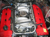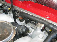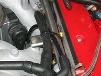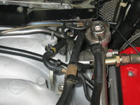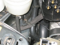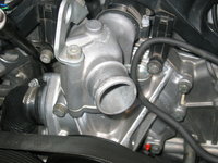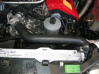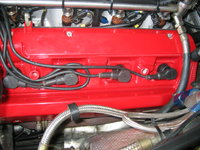
An update from Saturday, with about 3 hours total time spent out in the shop.
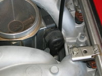
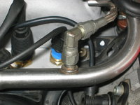
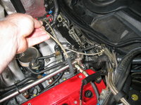
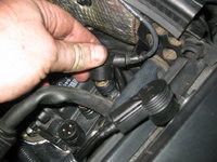
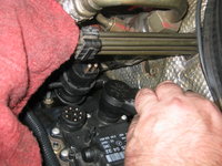
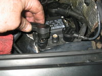
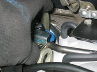
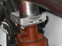
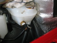
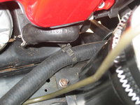
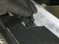
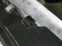
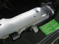
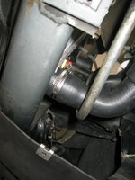
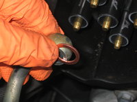
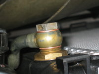
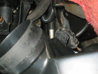
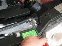
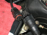
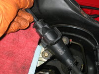
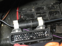
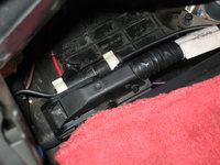
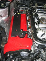
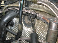
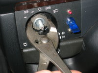
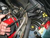
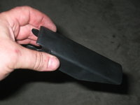
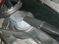
I installed the new "MOT" (purge or regeneration) valve onto its bracket, and then installed it back into the car. The rubber MOT valve surround is smaller than the original one that came with the car, but it is 100% compatible with the bracket and was a direct fit. In the photos below, you can see the new valve being fitted onto the bracket, in preparation for installation.


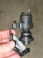
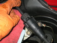
Fitting the valve and bracket into place, and tightening the two 10mm nuts that hold it to the fenderwall.


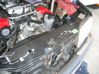
Here's what the valve looks like fully re-installed.

I then cleaned off the connector, and re-installed it onto the top of the valve.

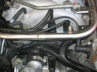
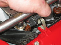
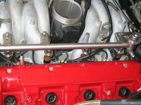
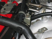
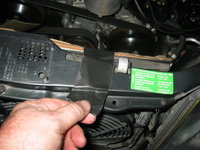
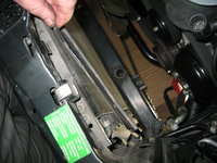
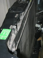
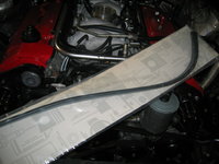
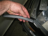
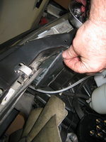
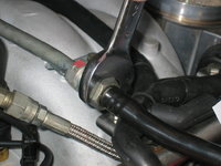
The next job was to complete a couple of steps that I hadn't yet done — re-connecting the final couple of pieces of the accelerator cable linkage together, and re-installing the vertical spring. The first photo shows the vertical linkage piece that connects the throttle cable plate's pivoting assembly to the intake manifold's pivoting assembly. I also hadn't installed the third small bolt that held the throttle cable plate to the intake manifold, so I also did this, as you can see in the second photo below. The third photo shows the vertical spring that goes between the two pieces. This spring is a bit tricky to fit, but some long needle-nose pliers make the job go much easier.


Next, I turned my attention to the new Automotive Lighting (nee' Magneti Marelli and/or Bosch) turn signals I'd recently ordered, and received. Below are a couple of direct comparisons of the left side lamp, and labels. As you can see, the "new" units made in the Czech Republic are of FINE quality, and every bit as good as the originals.


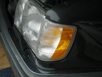
More interesting, you can see what 25 years of sunlight has done to the orange reflector in the outler lens itself. This right here is a good case for freshening up the front end, and made the $130 investment for the new lenses TOTALLY worth it.

Pulling the light bulbs out of the old turn signal assemblies, they looked old and quite tired. So I grabbed some of the bulbs in my parts stock, as shown in the first photo below, and installed them.


Here are a couple of views of the right-side lenses ... old faded and new crisp.


And, a few shots of re-installing the new bulbs, and then then lenses, back onto the car.


Here's what the new, crisp, sharp turn signal lenses looked like, installed. Quite nice.

The next step was to install the fuel injectors into the intake manifold, in preparation for the installation of the fuel rail. I had gone back and forth on this, at first decided to install the injectors into the manifold, then opting to install them directly into the fuel rail.....but then after more reading and thought, I decided to push them into the manifold, and then re-install the fuel rail on top of them. The injectors take a fair bit of effort to push down into the manifold to their proper depth. I used hand pressure, with a folded-up piece of lint-free towel (fourth photo) to press each injector into place with the heel of my hand. I used a small amount of silicone grease on each injector's o-ring and the intake manifold injector hole to help ease installation.


Here's what an injector looks like, properly seated into the intake manifold.
NOTE: Early cars through about mid to late 1993 have a separate, plastic piece that presses into the intake manifold that the injector slides into. Later cars from late 1993 through end of production have a modified manifold that eliminates this piece; the injector slides directly into the manifold.

Here is what the injectors look like, fully seated into the manifold on each side. The injectors can be rotated in their holes, as needed, once mounted.


Next up — installation of the
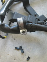
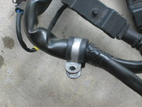
upper wiring harness. I pulled the harness out of storage and examined it carefully, taking an inventory of its condition and what needed to be mended or fixed. A few things came to light: one of the metal clamps was bad (shown in the second photo below), and the two plastic connectors at the cam adjuster solenoid connections had broken. Fortunately I had spares of all of these, so it was not too difficult to repair.

Here are a couple of photos of the label on my wiring harness. I had replaced it many years ago (around 2005), when I was living in Portland, Oregon.


First, replacing the clamp.
Then I moved on to replacing the plastic connectors for the cam solenoids. I cleaned the pin bushings after extracting them from the broken pin bushing housings.


And, the refurbished pin bushing housings for the cam solenoid connections.
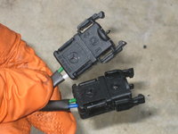
Next, I grabbed the upper wiring harness and loosely fit it into position. I had to work its larger plug end through the hole in the inner firewal where the
lower wiring harness and the heater hose go through, but this wasn't too difficult...


The next few photos show me wrestling the harness into general position where it needs to be.

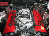

Moving the ETA cable into position...

Then, I moved the fuel rail into general position on top of the wiring harness. I took a Q-tip with a little motor oil on it, and carefully and lightly swabbed the upper o-ring of each fuel injector with motor oil, to ease its sliding into the fitting on the fuel rail. The third photo below shows the clips, and the small water bottle cap-ful of motor oil that I used as a small oil container for the Q-tip.

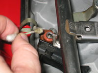

Moving the fuel rail into final position above each fuel injector, and pressing the rail down evenly across it onto the injectors. You should generally hear a small "click" or "pop" when each injector's o-ring fits into the fitting on the fuel rail.

The photo below shows a seated injector in the fuel rail.

And once the injectors are fitted into each port on the fuel rail, then you can add the clips. The clips slide into a small slot onto the top of each injector, and around the rounded fitting on each rail. There is a rectangular projection on one side of each injector (you can see it in the photo directly above) that fits into a slot in each clip.

And here is the fuel rail, in place, with all clips installed.

I fitted each fuel rail hold-down bolt into its attachment point in the top of the intake manifold, but only screwed each bolt 1-2 turns into the manifold.


For the passenger side of the fuel rail, the upper wiring harness's plastic "J" tube needs to be fitted on top of the fuel rail connection point. This is just two of the three bolts on that side. So I removed those bolts, and as shown below, moved the upper harness "J" tube into place, and re-installed the two 10mm fuel rail bolts that hold it down. I did not tighten anything down, yet.
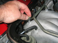
At that point, Laura came out to the shop and let me know that the homemade pot of chili that she'd been cooking all day, and the scratch-baked cornbread she'd just made, were done, and we were ready for dinner. So, I somewhat abruptly knocked off for the day.
More to come.....stay tuned !!



![[500Eboard] IMG_8666orig.jpeg [500Eboard] IMG_8666orig.jpeg](https://www.500eboard.co/forums/data/attachments/111/111913-52f10dd6d18cc44f53744e526c5bbd2e.jpg?hash=UvEN1tGMxE)
![[500Eboard] IMG_8666.jpeg [500Eboard] IMG_8666.jpeg](https://www.500eboard.co/forums/data/attachments/111/111914-bbd66fd7537161faa60e89d14f3a7a28.jpg?hash=u9Zv11NxYf)


