• Hi Guest !

    Welcome to the 500Eboard forum.

    Since its founding in late 2008, 500Eboard has become the leading resource on the Internet for all things related to the Mercedes-Benz 500E and E500. In recent years, we have also expanded to include the 400E and E420 models, which are directly related to the 500E/E500.

    We invite you to browse and take advantage of the information and resources here on the site. If you find helpful information, please register for full membership, and you'll find even more resources available. Feel free to ask questions, and make liberal use of the "Search" function to find answers.

    We hope you will become an active contributor to the community!

    Sincerely,
    500Eboard Management

RESTO PROJECT: M119 / W124 / E500 Engine Top-End Refresh

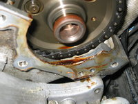
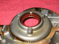
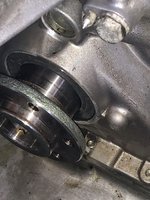
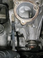
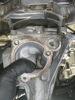
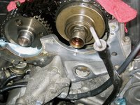
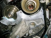
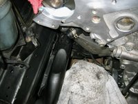
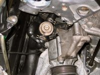
See my previous post — I added some photos at the end. It looks to me like the seal is nearly flush with the timing cover. No question it is original. I will do the latter like you did, but will also gauge with the seal tool.
 
I've also decided overnight and this morning that I am going to replace the water pump, along with the planned thermostat replacement. Reason being is that I have done all of the work that would be pre-required to do the water pump, and drained the coolant. I have a spare, new water pump and gasket sitting on the shelf in the garage, and the water pump on the engine is the original one (144K miles).

It's literally incremental labour to replace the pump at this point. So, yet another task to do as part of this big job.

:plusone: That makes sense Gerry. Hang onto the original MB pump though you might be able to turn it in for a MB reman in the future.
 
See my previous post — I added some photos at the end. It looks to me like the seal is nearly flush with the timing cover. No question it is original. I will do the latter like you did, but will also gauge with the seal tool.
Gerry, I did look at your photos, and it is definitely not flush with the face of the cover. If you install the tool with the 3mm lip against the seal, if it were flush, you could slide a 3mm thick pair of feeler gauges between the cover and tool. You can use feeler gauges to measure the exact inset before removing the seal.

:strawberry:
 
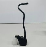
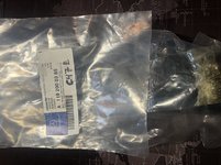
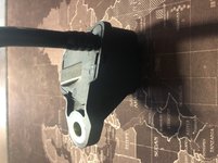
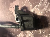
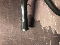
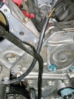
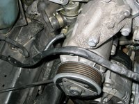
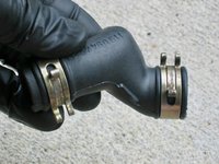
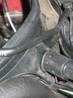
One note: the coolant "weep hole" reservoir from the water pump with the long black hose down that bolts to the timing cover, part 119 200 03 85, is now NLA from MB, and will not be produced further.

I will plan to re-use my existing reservoir.

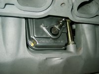
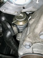
The reservoir is in the attached photo.
 

Attachments

  • b75de144-4551-4957-a008-09115817424d.jpg
    b75de144-4551-4957-a008-09115817424d.jpg
    93.9 KB · Views: 95
Last edited:
Gerry, I did look at your photos, and it is definitely not flush with the face of the cover. If you install the tool with the 3mm lip against the seal, if it were flush, you could slide a 3mm thick pair of feeler gauges between the cover and tool. You can use feeler gauges to measure the exact inset before removing the seal.

:strawberry:
Now that I look at the photos more closely (I was using my phone last night, and not wearing my glasses), you are correct. The seal looks like it is installed about 2mm inboard of the edge of the timing cover. I will confirm this when I go back out to the shop later on. I will do as you did and install it flush or very slightly protruding from the edge of the timing cover, which should place it 2-3 mm off-set from where the old seal's lip lay on the hub.

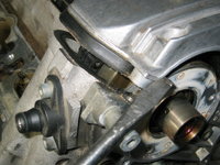
You can clearly see the groove on the hub where the old seal's lip was.
 
I was able to secure a NOS reservoir, which will be delivered to me on Monday of next week, for essentially the same as the price it was being sold for via my MB parts sources. New parts are always a good thing, especially when you score an "NLA" item.
 
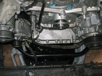
Spent about 30 minutes tonight starting to clean the front crank seal and oil-pan area.

Before I started, I re-inserted the hub onto the crank snout about one inch past the crank seal This closed the opening into the timing chain area exposed by removing the hub, so that no dirt from the cleaning process could enter the engine.

Here's a "before" photo:
[500Eboard] IMG_9075.jpeg

First, I took a plastic razor blade and a spatula, and scraped off as much dirt and grime as I could. It was half an inch thick on the top of the forward part of the oil pan.

After the bulk of the grime was scraped off, I began cleaning the area with brake cleaner.

Here are the initial results, after about 2.5 cans of brake cleaner. A good start on things, although there is much work to do.

8C7D25EF-FE09-471F-9925-16AEFD7ABB3C.jpeg 6E34DCE6-3A66-4A72-8189-8227569D7D93.jpeg 55F6A84A-4492-4A41-82FD-F5EABB60D51D.jpeg

I looked more closely with things cleaned, and found that the front crank seal was around 1.5-2 mm inset into the timing cover. Much easier to see after I cleaned it. So I'll definitely put the new seal around 1mm proud of the timing cover, as @gsxr has done in the past.

My next step will be to remove the water pump for additional cleaning, and replacement with the spare on my shelf after the front of the engine is cleaned up.
 
Last edited:
I have three cans left from my pre-job "stash," plus the case of 10 cans that I recently bought. I think I'll probably end up using about 5-6 cans total for this job. The hard part begins today -- I will use the aircraft-grade Simple green and spray the area, and clean it with a toothbrush as best I can. Then I'll go over everything for the final pass with brake cleaner.

First off, though, the water pump is coming off to make more room.
 
Could you please briefly explain why you will be using aircraft simple green and not automotive simple green here? Thanks
Regular "green" Simple Green is not good for use on cars -- specifically aluminum. It very dramatically attacks aluminum and corrodes it.

The Aircraft or Automotive Extreme Simple Green is safe for use with aluminum.

 
Regular "green" Simple Green is not good for use on cars -- specifically aluminum. It very dramatically attacks aluminum and corrodes it.

The Aircraft or Automotive Extreme Simple Green is safe for use with aluminum.


Gerry, my question was as to why you decided to use "aircraft simple green" vs "automotive simple green". Are they interchangeable with just different labels for marketing purpose? Thanks
 
Today, a couple of notable parts came as one of the parts orders I made.

First, the coolant weep reservoir, which is an NLA part from MB. I managed to find a NOS one pretty much at the same price as the last known MB price.

15E7051D-D767-4ED0-8A96-5A8B5FEC87F0.jpeg 77DD1B48-7000-432A-A4CF-88E86DACB123.jpeg 16074081-3752-46D9-B864-2EF3AFD393C2.jpeg 7835DD54-F6AF-41C4-AE0E-BF1811FF76E4.jpeg EC521B0B-36BC-45EB-800D-0192D9824913.jpeg6D1104CA-803B-46D6-8057-162359EFBFD3.jpeg

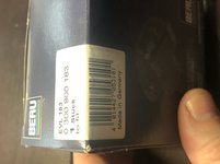
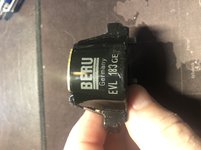
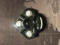
I also got two Beru rotors, whcih @gsxr says are the best way to go for rotors -- not to purchase Bosch or Bremi ignition stuff, with the exception of the distributor insulators (of which Bosch and OE MB are the only games in town). The rotors were production date July, 2018 and the box is marked Made in Germany.

B0467410-F24B-47E9-8106-F72828FFAE60.jpeg 6DB4E614-F9E4-455E-A7ED-F479027EDF6F.jpeg C2516148-AB18-4548-9D4B-D839ABB02B17.jpeg 21F171B0-CDEE-49D5-BABF-E2712ACFFAFA.jpeg

I have Beru caps on order, and a pair of new Bosch insulators. I expect them to be here in a few days -- just in time to start putting things back together.
 
Between the coolant weep reservoir and the lower splash guard, I don't know which part is less present on our cars today. Too bad the reservoir isn't clear so you can see if there is any coolant weeping out for an early warning of pump failure.
 
Those Beru rotors are reboxed OE/Genuine Doduco. If you look closely at the top you'll find the MB part number, and also the Star log, both covered in lacquer.

:shocking:
 
Today, I worked out in the shop for about 2.5 hours. Tasks were mostly cleaning parts, and removing a few more items from the front of the engine to facilitate further cleaning. I'd say that I am about 80% complete with cleaning on the front of the engine.

Here's the order of business for the day.

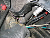
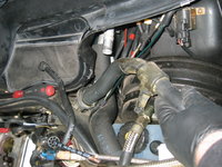
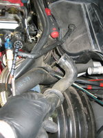
First, I had previously decided to replace the lower radiator hose, and have a new one on order. I disconnected the coolant level sensor, and then removed the lower radiator hose and removed it from the car.
IMG_9082.jpeg IMG_9083.jpeg IMG_9084.jpeg IMG_9085.jpeg IMG_9086.jpeg


When removing the lower radiator hose, it is held to the passenger side frame rail with two zip ties. Be sure to release (or at least loosen) the zip ties to free up the hose extension that goes from the radiator up to the coolant expansion tank.
IMG_9087.jpeg IMG_9088.jpeg


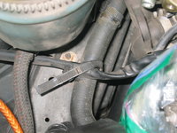
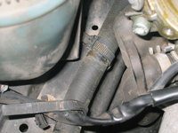
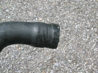
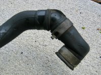
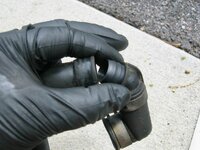
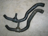
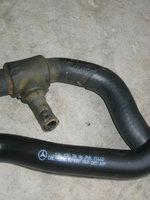
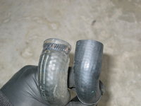
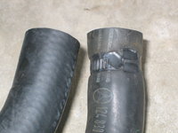
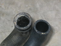
Here's the lower hose as removed form the car. You can see, by examining the ends of the hose, that they are swollen and bowed out a bit. Probably fine for another 5-10 years, but incremental labor to replace, and a prudent thing to do. Again, these are the "overlooked" items that many people who insist that THEIR car has no deferred maintenance, are completely ignorant of.
IMG_9089.jpeg IMG_9091.jpeg IMG_9092.jpeg


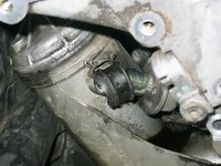
Next up, it was time to remove the thermostat housing and the "short hose" that attaches to the housing. Two clamps and a screwdriver to pry the hose off, and it was off. I had replaced this hose several years ago when I lived in Texas, when I last replaced the thermostat. However, I slightly ripped the edge of it -- not enough to affect it -- with the screwdriver, so I will replace it with another factory spare short hose that I have in my parts stock.
IMG_9094.jpeg IMG_9095.jpeg


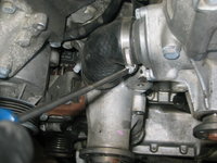
With the thermostat and housing removed, it is time to begin removing the water pump. First, use a 6mm Allen socket to remove the three bolts that hold the upper radiator hose connector to the top of the water pump. This is a simple item to do. Remember to order a new gasket for when you put it back together!!
IMG_9096.jpeg IMG_9097.jpeg IMG_9098.jpeg IMG_9099.jpeg IMG_9100.jpeg


Here's what the housing looks like, removed.
IMG_9101.jpeg


Remove the three 10mm bolts that hold the thermostat housing to the side of the water pump.
IMG_9102.jpeg IMG_9103.jpeg IMG_9104.jpeg IMG_9105.jpeg IMG_9106.jpeg IMG_9107.jpeg


Then extract the thermostat from its position in the water pump. This was a Behr thermostat that is around 5-6 years old, so generally speaking it was time to replace it.
IMG_9108.jpeg


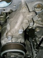
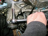
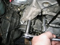
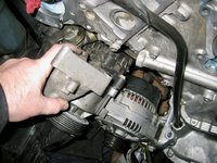
Then it's time to remove the water pump itself. There are six 13mm bolts that hold the water pump to the front timing cover. Pay attention to where each bolt goes, because there are several lengths of water pump bolts. I also removed the four bolts that held the alternator support carrier to the front timing cover. Loosening the lower alternator bolt allowed the removal of this alternator support carrier.
IMG_9109.jpeg IMG_9110.jpeg IMG_9111.jpeg IMG_9112.jpeg IMG_9113.jpeg


Next, I spent the better part of an hour cleaning things. Here is the cleaned-up upper radiator hose intake, which is bolted atop the water pump. I noticed a little pitting on the hose attachment, as shown in the first photo, but it was not enough for serious concern at this point in time. However, I will watch it in the future, as this type of corrosion (though common) doesn't get any better.
IMG_9114.jpeg IMG_9116.jpeg


I next removed the "triangle bracket" that attaches to the A/C compressor and the oilpan area. This is held on by three 13mm bolts, and one 10mm bolt that also holds a clamp for the SRS high-pressure hose to the oilpan.
IMG_9117.jpeg IMG_9118.jpeg IMG_9119.jpeg


Removing this clamp shows that its rubber insert is gone, so it will be replaced (along with the other two identical clamps that hold the SRS hose to the engine.
IMG_9120.jpeg IMG_9121.jpeg


Here are a couple of photos of the alternator bracket being loosened so that the alternator support carrier can be removed from the car.
IMG_9122.jpeg IMG_9123.jpeg IMG_9124.jpeg


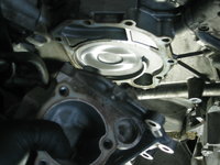
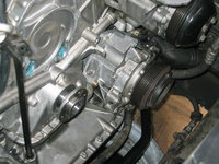
Removing the last, long, bolt from the front of the water pump, I then removed it from the engine. It is important to also remove the water pump gasket and clean the front of the timing cover, so that when the water pump (or a new water pump) is (re)installed, it will have a proper sealing surface.
IMG_9125.jpeg IMG_9126.jpeg IMG_9127.jpeg


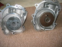
Here are comparisons of a new-in-box Graf water pump, on the left, with the working MB water pump on the right. The Graf pump has noticeably poorer quality casting, and seemingly a plastic impeller, as opposed to the metal impeller of the MB pump.
IMG_9128.jpeg IMG_9129.jpeg IMG_9130.jpeg IMG_9131.jpeg


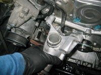
Removing the alternator support carrier from the engine.
IMG_9134.jpeg


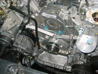
I then went to work cleaning the engine, where I'd left off the other night. Here is the result of my work. More to do, but notably cleaner than before. Still have some work to do to clean up the water pump gasket sealing surface, as well.
IMG_9135.jpegIMG_9136.jpegIMG_9137.jpeg
 
Your water pump area looks pretty nice GVZ, no bad scale - a great sign of dutiful ownership past and present. Distilled water has been a friend.
 
Beautiful! Maybe it's worth returning Graf and get MB remanufactured part?
@kiev -- I've been thinking since yesterday. I may put the "old" water pump back on the car, since it was working fine. The impeller and shaft are operating smoothly, and I have two water pump gaskets. I am thinking I may just clean it up and re-install it when the time comes in the future. Need to think about it some more.
 
Today I have a little more work to do on the intake stack -- specifically re-installing the throttle linkage and the cruise control linkage to the back of the intake manifold, and to the ETA. I'll finish cleaning up the front of the engine.

I'm hoping also to get the front crankshaft seal replaced today. The front crank seal is really the centerpiece of this whole operation -- the genesis for the entire job, as it has been leaking for a number of years now. As well as a small valve cover gasket leak.

Looking forward, I plan to remove the valve covers and the front cam covers, so I can clean them up well, remove the old anaerobic adhesive, and install new cam seals.
 
Today, I spent around 1.5 hours doing a couple of tasks. Specifically, I finished the build of the intake manifold stack, and also removed and replaced the front crankshaft seal.

I went out to the shop and grabbed the mostly completed intake stack, from where I had it stored. The job for today was quite simple -- to re-attach and connect the throttle and cruise control linkage to the ETA. This was a simple task, but I took my time and savored it.

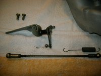
First, I laid out the individual pieces on the table, in preparation for the job. I did this after spending a few minutes cleaning all of the pieces and the two bolts. I basically wanted to get the grease and grime off of all of the parts.
IMG_9138.jpeg


Next, I laid the intake stack partially on its side, and rotated the end of it so that I could see the flanges on the end where I would be attaching the linkage plate. I also took a look at the side of the ETA where the linkage and spring would be attached.
IMG_9139.jpeg IMG_9140.jpeg


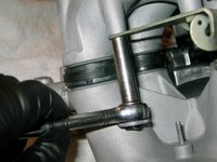
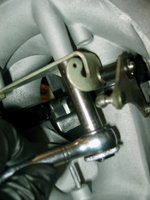
Then I put the linkage plate in place, and inserted the two 10mm bolts by hand. Then I used a socket to tighten them appropriately.
IMG_9141.jpeg IMG_9143.jpeg IMG_9144.jpeg IMG_9145.jpeg IMG_9146.jpeg


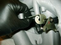
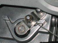
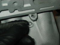
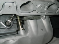
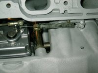
The next task was to attach the ends of the spring to the ETA arm, and to the eyelet on the side of the intake manifold's upper half. This was not too difficult. The long-armed end of the spring is attached to the ETA; the short loop is attached to the intake manifold's eyelet.
IMG_9149.jpeg IMG_9150.jpeg


Here's what the spring looks like, appropriately installed.
IMG_9151.jpeg


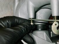
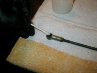
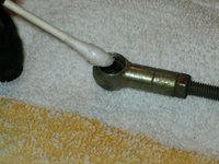
Next up is the installation of the arm to the throttle linkage plate and to the ETA arm. Before attaching this piece, I took a Q-tip and liberally spread some synthetic grease into each of the ball sockets at the ends of the linkage arm.
IMG_9152.jpeg IMG_9153.jpeg IMG_9154.jpeg IMG_9155.jpeg


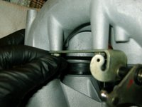
Then I attached each of the sockets onto the balls. A pair of bent-needlenose pliers helped persuade the sockets onto their balls. After that, I wiped up the synthetic grease that squeezed out of the sockets, and observed my work with satisfaction. Then I brought the intake stack back out to the garage for further storage, until it is needed for installation.
IMG_9158.jpeg IMG_9159.jpeg


The second part of today's work -- and arguably one of the most important jobs of this entire HOW-TO, was the replacement of the front crankshaft seal, which had a moderate and long-standing oil leak of several years. Here is a photo of the crank snout, crank hub and seal as I had left them. I had pushed the hub back onto the end of the crank and slightly past the crank seal to provide a barrier against dirt, brake cleaner and grime that I had previously cleaned off of the front of the engine.
IMG_9160.jpeg


The first step was to pull the crank hub off of the end of the crank.
IMG_9161.jpeg


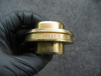
Next, I grabbed my handy Miller 9101 crank seal installer. Per @gsxr's request earlier in this thread, I inserted both sides of it against the end of the timing cover to try to gauge the depth of the old crank seal.
IMG_9163.jpeg


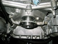
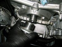
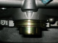
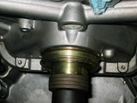
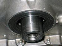
Here are photos of the two sides of the installer against the timing cover, for reference. From what I could see with my naked eye, it appears that the seal was installed in a 1.5-2mm inset position in the end of the timing cover. I believe that this is the original crank seal.
IMG_9164.jpeg IMG_9165.jpeg IMG_9166.jpeg


Next, I needed to remove the old crank seal. Using the factory service manual instructions, I first tried to remove the seal using a screwdriver, padded by four folds of a thick towel. Despite doing this in a number of positions, I ended up slightly scoring the crank snout through the folds of towel, even being very careful. It seems the crank snout is VERY soft metal -- much softer than I had thought. You can see the scores in the third photo below.

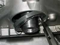
Finally, I decided to just get out my seal puller tool, which didn't touch the crank snout and immediately removed the seal, and it came out easily. Here are two views of the seal coming out.
IMG_9167.jpeg IMG_9168.jpeg


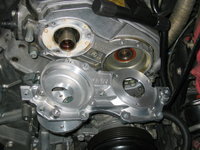
And here is a photo of the timing cover with the crank seal removed. You can see the timing chain (and perhaps a lower chain rail) through the hole.
IMG_9169.jpeg


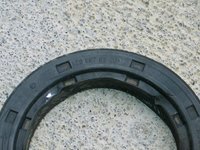
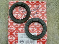
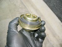
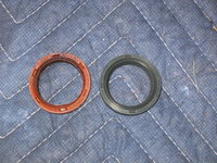
A couple of views of the freshly removed seal - a Bruss branded seal with factory MB part number. Third photo is a photo of the old seal (upper left) next to the new seal (lower right).
IMG_9170.jpeg IMG_9171.jpeg IMG_9172.jpeg


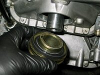
Then it was time to install the new seal into the timing cover. This was a simple and straightforward operation. First, the seal is placed on the appropriate side of the Miller seal installer.
IMG_9173.jpeg IMG_9174.jpeg


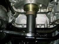
Next the installer is slid onto the end of the crank snout, and pushed into place.
IMG_9175.jpeg IMG_9176.jpeg


And the next step is to screw the crank bolt and washer stack into the end of the crank snout. The bolt and washers will be used to "push" the installer and seal along the end of the crank and into position in the timing cover.
IMG_9180.jpeg


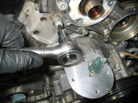
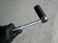
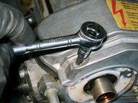
Preparing my 27mm socket (1/2" drive for this operation), I began tightening the crank bolt, which in turn began pressing the seal into the timing cover. Here you can see the operation progressing gradually.
IMG_9181.jpeg IMG_9182.jpeg IMG_9183.jpeg


After getting the seal most of the way, I removed the bolt to check progress. I had not installed the seal quite enough into the timing cover, so I re-installed the Miller seal installer and crank bolt, and tightened things further until I reached the depth I desired.
IMG_9184.jpeg IMG_9185.jpeg


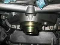
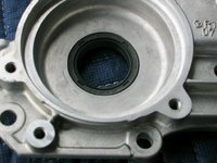
Here is the final position of the front crank seal -- about 1mm proud of the timing cover. This should place the seal at an offset of 2.5 to 3mm from where the "old" seal contacted the hub -- far enough away that it will provide a solid seal.
IMG_9186.jpeg


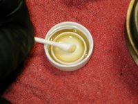
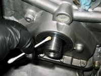
After the seal was installed, I put some oil into a small cap, and doused the end of a Q-tip into it. I then lightly oiled the sealing lip of the new seal, in preparation for the re-installation (pushing in) of the hub to re-seal things and keep air, dirt and moisture out of the oilpan and lower part of the engine. I lightly pushed the hub back onto the crank shout, positioning it so that the hub just pushed past the edge of the new seal.
IMG_9177.jpeg IMG_9178.jpeg IMG_9179.jpeg IMG_9187.jpeg

I finished up the afternoon by doing further cleaning of the front of the engine with a toothbrush and a half-can of brake cleaner. I was able to remove a fair bit more dirt and grease from areas that I hadn't been able to get previously.
 
A lot of parts delivered today, with one more batch of parts from MB yet to come.

I received the following:
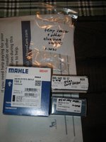
  1. Two Beru distributor caps -- made in Germany
  2. Two Bosch distributor insulators -- made in Spain
  3. Two Mann air filters -- made in Germany
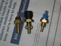
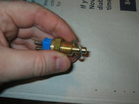
  4. One Beru four-prong coolant temp sensor -- made in China
  5. One Beru single-prong coolant temp sensor -- made in Ireland ***has MB star/part number with XXXXXX through it
  6. One Mahle/Behr two-prong coolant temp sensor -- made in Czech Republic
  7. One MB lower radiator hose -- made in Germany
 
I would install that Graf Water Pump Gerry, plastic impeller or not. It is a decent brand of part and I'd rather have a new pump in there given the opportunity you have now. The old one is nearing the end of its life it would be a shame for you to have to go back in to mess with the crank pulley any time soon. What else will you do with the pump anyway - sell it on? Use it and I'm sure it will be totally fine!

By using the old pump you are willing to go back in there anyway - so put the Graf to work and dont fret about the construction of it. Again- they are a good brand so should know what they are doing.
I pretty much came to the same conclusion, and will do so. I have no issue with Graf, really.

I do have to finish cleaning off the water pump gasket area - I have most of it done, but still a little work to do to make sure I get a perfect seal. Big batch of parts came in yesterday, as mentioned, so I'm damned close to being where I need to be parts-wise. Still waiting on my cam solenoids and armatures from MB, but once those come in (today?) I'll remove the front cylinder head covers (and valve covers) and clean them, and install the cam solenoids and such.

Thanks for your input, @JC !! coalisland for the win !!
 
First off, though, the water pump is coming off to make more room.
Don't put the new water pump on the engine before you finish replacement of the front oil seal, put the hub back and torque the crankshaft bolt. It will be much easier to maneuver the large torque wrench w/o the pump in place.
 
Don't put the new water pump on the engine before you finish replacement of the front oil seal, put the hub back and torque the crankshaft bolt. It will be much easier to maneuver the large torque wrench w/o the pump in place.
Good advice, and thank you for reiterating it. I won't plan to put the water pump back on until pretty much everything is done on the front of the engine (the cylinder head front covers and associated components are next). I'm probably going to drain the torque converter and transmission (after replacing the front transmission cooling lines) also before doing the water pump, seeing as it's time with the age/miles on the trans fluid, and I already have the crossover pipe removed for much easier access to the torque converter drain plug.

My 3/4" drive crankshaft bolt socket doesn't arrive for about another week, so there's plenty of time to get a lot of stuff done...
 
A lot of parts delivered today, with one more batch of parts from MB yet to come.

I received the following:
  1. Two Beru distributor caps -- made in Germany
  2. Two Bosch distributor insulators -- made in Spain
  3. Two Mann air filters -- made in Germany
  4. One Beru four-prong coolant temp sensor -- made in China
  5. One Beru single-prong coolant temp sensor -- made in Ireland ***has MB star/part number with XXXXXX through it
  6. One Mahle/Behr two-prong coolant temp sensor -- made in Czech Republic
  7. One MB lower radiator hose -- made in Germany


Gerry - for items 4/5/6, did you buy new washers for them?
 
Yes, I purchased new Elring aluminum washers for all three of these coolant temp sensors. Only one of them -- the four-prong sensor -- came with a washer in the box. I already have around 20 of these washers in my spare-parts stock, but I got three new ones anyway.
 
Gotcha, I thought that might be the case but others who are "late to the party" so to speak, may not know your impeccable habits....
 
Sad that the Beru four-pin temp sensor is now Chinese. Was that OE or OEM?

:hiding:
 
A couple of small tasks that I did while taking a short break for lunch today.

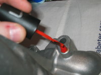
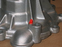
First, the I stole a bottle of Laura's fingernail polish out of her drawer -- a bright orange variety -- and used it to "paint" the TDC indicator marker on the Graf water pump. Not that the old MB water pump had this marker painted red or orange, but I wanted to help it stand out. Three quick coats of nail polish over an hour or two did the trick.
IMG_9189.jpeg IMG_9191.jpeg


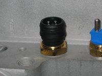
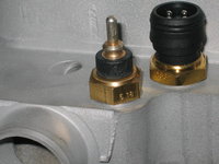
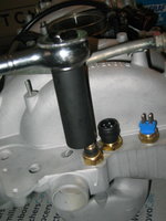
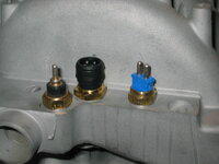
Second, it was time to install the three coolant temperature sensors that I received in my parts order yesterday. This officially finishes out the re-assembly of the intake manifold, and it is safely stowed away in the shop and ready for [eventual] re-installation at the proper time. It is important to get the sensors in the correct order. From left to right -- one-prong, four-prong, and two-prong.


Here's what the bare intake looks like with no sensor installed, and the collection of parts (and Elring aluminum washers) I had received.
IMG_9192.jpeg IMG_9193.jpeg IMG_9194.jpeg


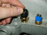
Then it was time to install the sensors. It's best to install the black (center four-prong) sensor first, as it uses a 22mm socket (or wrench). The other two sensors (which are 19mm) tend to get in the way of getting a good purchase on the center sensor, unless you are using a deep socket. However, a deep socket will not fit on the four-prong sensor, because the black plastic body is larger than the hexagonal section used to tighten it.

So just trust me (and it is not indicated in these photos very well) -- install the center four-prong sensor first, and THEN install the one-prong and two-prong sensors.
IMG_9195.jpeg IMG_9196.jpeg IMG_9197.jpeg IMG_9198.jpeg IMG_9200.jpeg IMG_9201.jpeg IMG_9202.jpeg IMG_9203.jpeg


And here's what all three sensors look like, installed !! The intake manifold is now DONE.
IMG_9204.jpeg


One note, per my post above. I will likely clean up the old MB four-prong coolant temp sensor, and replace the Chinese-made one (which I installed in the photos above) with it. But I'll do this as one of the last steps before I add new coolant to the system, when the job is almost complete.
 
Today, I didn't do much on the car, and only spent about an hour in the shop. It was more of a "yard" day to get things done on the outside of the house. Consequently, I didn't even get to the car until about 6:30 PM.

Also, unfortunately, my Canon PowerShot "shop" digital camera finally died tonight. I have had it since I bought it in early 2003, when I bought it just before my ex-wife and I went to Vladivostok, Siberia, Russia to adopt our daughter Sofia (who is almost 17 years old now). That camera has taken around 49,000 photographs over its life, and has done the majority of the HOW-TO photographs for those articles I've posted.

FORTUNATELY, I have purchased a couple examples of the same camera over the years on eBay. First I got one as a parts camera, and about 5 years ago I bought a near-new one as a spare, for the eventual failure or demise of the camera, which happened when I bumped it off of the radiator support, and it fell down onto the lower radiator support and somehow messed up the digital display.

I decided to forge ahead with my tasks for the night, and then after I was done I went and dug up my spare camera, set it up, and will continue using it tomorrow.

Here are the tasks that I did tonight.

First, I removed the old Fichtel & Sachs fan clutch from the fan, loosening and removing the four 10mm bolts. This was an OE clutch from a 1992 500E that had 50K miles on it. It worked better than the worn original clutch, but still was not 100% in high ambient temps. I replaced it with the spare Horton MB OE clutch that I bought in 2016. We'll see if the Horton clutch is adjusted correctly from the factory, or not.

Next, I removed the passenger side valve cover. It came off without too much issue. I believe the small oil leak I had been experiencing was from the rear outer valve cover bolt not being tightened (torqued) enough when I last removed the valve covers to replace the plastic cam oiler tubes with aluminum ones, about 5-6 years ago. The interior of the heads was spic and span (super clean). As I may have previously mentioned, I plan to replace the valve covers with the red powder-coated ones I had done a couple of years ago here in Maryland.

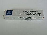
After removing the valve cover, I removed the bolts that held the front cylinder head cover onto the front of the head. It was pretty obvious that all of the bolts had used orange koala-claw sealant from the factory, along with the cylinder head cover's sealing surfaces to the front of the head, as well as the cam solenoid.

Tomorrow, with the front head cover removed, I'll press out the old cam seal, which was leaking modestly. I have new replacements and will use a 29mm socket as a mandrel to press out and then press in new seals. The factory seals are pressed into the front of the head cover at a depth around 1.5 mm below the edge of the cover. I will re-install the new seal generally flush with the edge of the cover.

Now that I have my replacement camera working, I can capture the replacement of the seal, and the re-assembly of the valve cover, installation of the new gasket, and so forth. Then I'll capture the entire process on the driver's side.

Replacing the cam seals will be INFINITELY easier with the front cylinder head covers removed from the car.
 
Today I spent about 4.5 hours out in the shop, while the forum's software restore from backup was ongoing. I'll talk about that in another thread.

Only had one photo from last night, before my camera died. That was the first photo of loosening the cam cover bolts, which are 5mm Allen-head bolts. I loosened a few on the driver's side, but loosened all of the bolts on the passenger side cam cover, and removed it from the car, as mentioned.
IMG_9205.jpeg


This morning, when I started working on the car, I focused on cleaning up the front cover for the passenger side cylinder head. Here is what it looked like after about 30 minutes' work -- as compared to the driver's side cover, which is still installed on the car. I used a Scotch Brite pad soaked in brake cleaner to scrub off all of the old anaerobic sealant, with a razor blade tip used to get in the corners where the pad couldn't reach. Chlorinated brake cleaner works well to soften up the dried-up anaerobic sealant. Anyhoo, here's what it looked like when I was done cleaning.
IMG_9209.jpeg


Before I started scrubbing the cylinder head cover in earnest, I pressed out the old (reddish-brown) camshaft seal from the cover using a 30mm impact socket. Worked well, and the seal came right out. Here is what the seal looked like, compared to the new (black) Elring seal that was soon to be pressed into the cylinder head cover.
IMG_9210.jpeg IMG_9211.jpeg


The old camshaft seal was noticeably stiffer and more fossilized than the new seal, particularly along the sealing edge that touches the camshaft. I also could see small "micro cracks" in the surface of the seal, telling me that it was probably not far away from causing a major oil leak and in strong need of replacement.

Using the other (slightly smaller diameter) ratchet end of the same 30mm socket, and a hammer, I was able to drive in the new seal carefully, and evenly. I used small hammer blows in a pattern all around the seal, which worked well. I pressed the new seal about 0.5mm below the front edge of the cylinder head cover. However, seeing as the old seal was around 1.5 mm below the front edge, and the fact that there is plenty of room behind the area to press the seal further in, I think I am going to press the new seal about 2-2.5mm further in, so it rests in a different spot that is further back on the camshaft.

Here are a few photos of the pressed-in seal, showing from the back-side that there is plenty of room to press it in further. Again, I think I'm going to push it in about 2mm further.
IMG_9212.jpeg IMG_9213.jpeg IMG_9214.jpeg


Next are a couple of photos of the camshaft area and the front of the cylinder head, as I began cleaning them with a Scotch Brite pad and brake cleaner. The first photo shows things about 30% cleaned; the second photo shows things about 80% cleaned.
IMG_9215.jpeg IMG_9216.jpeg


Next up, I turned my attention to the smog pump. After some deliberation in recent days, I decided to remove it for a few reasons:

1) To clean up the area underneath and behind it;
2) To replace all four of the smog pump hoses, which I'd ordered new ones of back in early 2018;
and 3) because I was curious as hell about the area !!


The first thing I did was to remove the sleeve containing the two vacuum lines from the vacuum valve behind the passenger-side front headlight to the intake manifold. These lines were fossilized, and one had actually cracked multiple times in the past! I threaded the sleeve with the vac lines through the smog pump bracket, and moved the lines out of the way. All of these will be replaced, of course, in due time.....
IMG_9217.jpeg IMG_9218.jpeg IMG_9219.jpeg IMG_9220.jpeg


This freed the smog pump to be removed. It is held to the front of the cylinder head by three 13mm bolts. Two of the bolts are the same size, and the third (lower) bolt is much longer. I made short work of removing them, noting when they came out that they were encapsulated with anaerobic sealant to prevent oil leaks.
IMG_9221.jpeg IMG_9222.jpeg IMG_9223.jpeg


After removing the three bolts, the smog pump came free, as you can see.
IMG_9224.jpeg


This also freed up space and line of sight to remind me of all of the dirt and grime that I'd missed in my earlier cleaning behind and below the smog pump and alternator. Sigh....
IMG_9225.jpeg


With the smog pump removed, it was time to start removing the hoses that connect it to the engine. I was very glad I did. I rotated the smog pump about 90 degrees and after loosening a couple of spring clamps, the hoses started coming free.
IMG_9226.jpeg IMG_9227.jpeg IMG_9228.jpeg IMG_9229.jpeg IMG_9230.jpeg


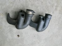
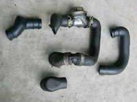
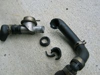
Here are the hoses and valve assembly, as removed from the engine.
IMG_9231.jpeg IMG_9232.jpeg IMG_9233.jpeg


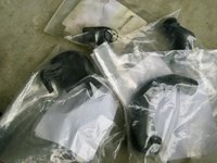
And it was time to break out my bags of new MB rubber smog pump hoses. No Harbor Fright smell here.....
IMG_9234.jpeg


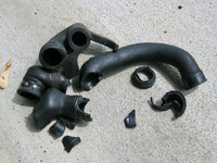
Some comparison photos of the old and new smog pump hoses.
IMG_9235.jpeg IMG_9236.jpeg IMG_9237.jpeg IMG_9238.jpeg IMG_9239.jpeg


A couple of the hoses had to be persuaded off with the tip of a flat-blade screwdriver.
IMG_9241.jpeg


A photo of the smog pump hose carnage ... but I'm not done yet !!!
IMG_9242.jpeg


The short hose that connects the smog pump to the engine was stubborn, so I just turned the smog pump more until the hose ripped off.
IMG_9243.jpeg IMG_9244.jpeg


Here's the new smog pump hose that connects the pump to the engine, loose and installed. Notice how all of the clamps and the valve are nicely cleaned in the next photos.
IMG_9245.jpeg IMG_9246.jpeg IMG_9247.jpeg IMG_9248.jpeg

NOTE: I can not tell you enough how badly the smog pump hoses were fossilized. They were so hard that if I would have thrown one, it would have easily broken a window, or given someone a concussion if it hit them in the head. All of the smog pump hoses are cheap from MB, and TOTALLY WORTH replacing. Particularly if you are "in there" doing an alternator replacement, a smog pump replacement, or this type of top-end job. Again, this is easily $500 of ALL cars' $5,000 or $10,000 of deferred maintenance. Age and heat kill this rubber.


With all new smog pump hoses re-installed, it was time to break out the ... yes, you got it !! .... orange koala-claw MB anaerobic sealant goo. This is EXPENSIVE stuff, but contains as I said, koala-bear claws, Japanese-grown satsuma pulp, and other esoteric ingredients to warrant that expense.
IMG_9249.jpeg IMG_9250.jpeg IMG_9251.jpeg


It's imperative to coat the ends of the 13mm bolts that hold the smog pump bracket to the cylinder head with the orange koala-claw goo.
IMG_9253.jpeg


Then you can tighten the bolts, to re-attach the smog pump to the cylinder head.
IMG_9254.jpeg IMG_9255.jpeg


Here's what things look like, re-assembled. It took me a LONG time to remove, clean, and then re-assemble everything, but it was totally worth it. Very happy.
IMG_9256.jpeg IMG_9257.jpeg


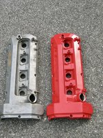
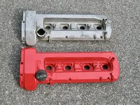
Next, just for a change of pace, I turned my attention to the valve covers. I will be replacing the valve covers with ones I had powder-coated red a couple of years ago. Here's what they look like, side by side. I did install the valve cover gasket to this passenger-side cover. After that wind-down, I called it a day.
IMG_9258.jpegIMG_9259.jpeg
 
Last night, I spent about 30 minutes out in the shop. Would have liked to have spent more, but work activity ran late, and I wanted to spend some quality time relaxing with Laura.

What I did was to remove the driver's side valve cover, and the front cylinder head cover. I documented these better, seeing as I wasn't able to document the passenger side the other night due to the unfortunate demise of my vintage "shop" digital camera.

Today I'll clean up the other front cylinder head cover, and will re-install both head covers and the red valve covers.

Here's the process.

First of all, a view of the driver's side of the engine, just for orientation. As you can see, I haven't cleaned that side of the motor yet where the intake manifold rests on the cylinder head. That will be one of the forthcoming jobs.
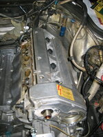
IMG_9260.jpeg


Using my 5mm Allen socket, and a 1/4" ratchet, I was able to loosen five of the seven valve cover bolts. The remain two, on the lower side and toward the rear (firewall), require the "swivel" 5mm Allen socket. This same socket is required for the rear-most lower valve cover bolt on the passenger side, as well.
IMG_9261.jpeg IMG_9262.jpeg


Here's the rear-most lower bolt, after loosening with the 5mm swivel Allen socket.
IMG_9263.jpeg


Using a large flat-blade screwdriver, I began wedging it (gently) between the front cylinder head cover's upper shoulder bolt, and the tab on the bottom of the valve cover. It doesn't take too much effort or pressure to begin to pry the valve cover free...
IMG_9264.jpeg IMG_9265.jpeg


Lifting the valve cover off of the cylinder head.
IMG_9266.jpeg


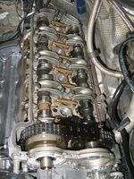
Here's the inside of my cylinder head. Looks pretty clean, even after a number of years since I was last in there (see my HOW-TO on replacing the cam oiler tubes). I've used RedLine full-synthetic oil, which has kept things very clean, and nicely lubricated. You can see that I did not clean the cam oiler tubes when I installed them -- I just fitted new o-rings and then installed them unwashed. The circulation of the motor oil has started to clean some of the brown cruft off of the cam oiler tubes, but it will take more miles and circulation to fully do this.
IMG_9267.jpeg


The next step after removing the valve cover, is to loosen the bolts that hold the cover to the front of the cylinder head. These are held on with 6mm Allen bolts. The long "shoulder" bolt fits at the upper position on the front (inside) of the cover. The longer 6mm Allen bolt (I believe it is an M8 x 35 size) goes in the position directly below the shoulder bolt. The remaining 6mm Allen bolts (of size M8 x 25) are all the same size.

The photos below show the shoulder bolt being loosened (first photo), and the M8 x 35mm ("long") bolt being loosened and removed (second and third photos). Make sure you clean these bolts up with solvent or cleaner before re-using them. They will likely be encased with grime and dirt/grease on the bolt-heads, and will have orange koala-claw anaerobic sealing goo (dried up, of course) on the threads.
IMG_9268.jpeg IMG_9269.jpeg IMG_9270.jpeg

When you re-install the cylinder head cover and its bolts, you will need to coat the threads with the orange koala-claw anaerobic sealant, as well as the sealing surfaces of the cover itself, where it mates to the front of the cylinder head. We'll cover that later in this HOW-TO.

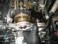
The next photos show the loosening and removal of the front cylinder head cover. It can be broken free by hand, after all of the bolts are removed.
IMG_9271.jpeg IMG_9272.jpeg


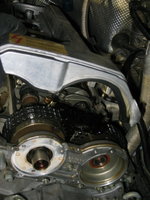
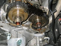
After you've removed the cylinder head cover, you see the front of the cam sprockets and intake cam adjuster. Cool stuff. You can see the very modest oil leak and associated dried oil. Although these oil leaks weren't that bad (they get MUCH worse), it was a totally logical thing to address while "in there" -- this is literally incremental labour given that I essentially have the entire front of the engine off anyway....not to mention was planning to replace the stock valve covers with the red powder-coated ones anyway.
IMG_9273.jpeg IMG_9274.jpeg


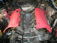
With the valve covers off, it was time for the driver's side cylinder head to join its Siamese Twin with a fresh protective layer of fresh shop rags, to protect from dust and such.
IMG_9275.jpeg


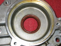
Now, it's time to turn to the cylinder head cover itself. Examining it closely, I could see that the cam seal was inset into the cover about 2mm. I will try to take better photographs, but when I replace it with the new seal, I will only inset it around 0.5mm into the cover. This should give about a 1.5mm off-set from the original position of the seam against the camshaft.
IMG_9276.jpeg IMG_9278.jpeg


A bit of discussion and observation, before I close.

First, again as with the passenger side, the camshaft seal was very stiff and un-flexible, particularly on the sealing lip where it touched the camshaft. I am sure this is both some use, but also age. The rubbery plastic, depsite having a round metal spring to reinforce it from behind, just gets brittle and hard from age. I can guarantee that if you have not replaced these cam seals yet, that yours are 1) either leaking fairly badly; or 2) are hard/brittle and will be leaking soon.

The cam seals (as our own "Triple Trouble" has shown in his OWNER thread), CAN be replaced while on the car, without removing the cylinder head covers. It is more difficult to get the new seals inserted squarely in the cover with it on the car, but it is certainly possible to do. I recommend, honestly, that if you ever do this job yourself, that just just take the time to remove the valve covers (7 bolts each side) and the front covers (six or seven bolts each side) and replace them off of the car.

Secondly, after really looking at this set-up with the cam seals and distributor insulators, I have come to a conclusion. This conclusion is that the "moisture" droplets that we see on the back-side of the distributor insulators, which has been an increasingly common occurrance for many owners that cause poor running characteristics, is really the result of a combination of oil and moisture "mist" that finds its way past the camshaft seal and attaches to the back of the distributor insulators.

It's a minute amount of "mist" that gets by the seal, but over time it builds up, and eventually provides a path(s) of lower resistance, for electrical spark to find its way down and "short" the ignition system. This is what causes the rough running and such.

This situation happens when the cam seals are old, hard and brittle ... and not sealing well against the end of the camshaft. This situation in reality can only be remedied by installing new camshaft seals, in conjunction with new insulators. New insulators will remove any established electrical pathways and conductive areas on the backs of the insulators, but new insulators by themselves WILL NOT solve the underlying problem, which is the fact that oil and water mist (in some combination) is finding its way past the cam seal.

Looking at my own car's characteristics, I did not have a bad oil leak on either side (a modest leak was all) and I also did not have horrible insulators on the back side. I believe, however, if my cam seals had worn further, that it would have only been a matter of time before more oil/mist would have found its way past the brittle cam seals, and onto the backs of the insulators ... and caused running problem on my car as well.

This is a totally different issue than moisture finding its way into the distributor caps from the front side (which I don't think is a major issue), as well as "green slime" inside the caps. I have personally experienced and observed distributor caps with major amounts of crud inside them running almost perfectly. One caveat -- this is very different from having the black electrical traces inside the caps that run from the center post out to each of the terminals. This is another "electrical short" situation where spark is finding its way via an alternate pathway of lesser resistance, thus shorting and causing rough running.

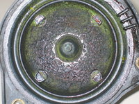
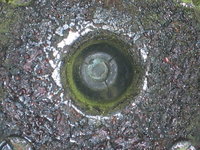
NOTE: Below are images of the insides of my original E500 distributor caps and rotors, which I replaced back in early 2004 when I lived in Portland, Oregon. Note that though these caps on my car were covered in green slime on the inside, the car idled and ran almost perfectly. I only noticed slight and occasional "hiccups" in the idle while sitting at stoplights. The situation disappeared after replacing the caps and rotors.
IMG_1434.jpeg IMG_1436.jpeg IMG_1437.jpeg IMG_1439.jpeg IMG_1431.jpeg IMG_1432.jpeg IMG_1433.jpeg

What I'm trying to say here is that there are two different ways that the M119 with LH (or CIS-E) can have distributor problems that cause rough running: a) by having insulators that have moisture/oil mist on the back side, caused by a failing cam seal; and b) having "alternate" electrical traces develop inside distributor caps, caused by moisture or other problems.

Both of these situations need to be carefully searched for and diagnosed.

Cheers,
Gerry
 
Today, my last two MB Annapolis parts orders came in.

Tomorrow, my fuel injection rebuild parts kit, and my 27mm 3/4" drive crankshaft socket, arrive.

These should be the very last parts orders that I have outstanding, and I will have 100% of the parts that I need to complete everything.

In the near future, I will post an updated listing of all parts and tools ordered to complete this job. Prepare to be staggered with the cost and extent !!
 
This is as comprehensive a list as I can make it of the parts that I have used (or will be using) for this Top-End Rebuild.
Some parts (and I have indicated them) were already in my parts stock, but I am listing them anyway, because I am using them as part of this effort. Other parts were ordered from both MB and aftermarket sources. I sort of do not want to do this, becuase I know the total amount of money just for parts, is going to be staggering. Not to mention the labor involved (and I'm only about one-third into this job as of now).
You all know my car has been generally well maintained along the way, and currently has just over 144,000 miles on it. My car was running perfectly when I started this operation, with the exception of a Check Engine Light being lit with codes 4 and 5, and a modest oil leak due to the front crankshaft seal. These are things that most owners would ignore, because the car was operating very strongly.

If anything, all of this effort certainly goes to prove the levels of deferred maintenance these cars carry, and the amount of parts, labor and money required to keep these cars in top running condition.


Part NumberList PriceNet Price I PaidQuantitySourceOrderedNotes
119 200 15 0185.5085.501Pelican PartsJan-2018Graf water pump for M119.
119 201 03 805.255.251Pelican PartsJan-2018Genuine MB water pump gasket to engine.
120 997 03 466.506.502Pelican PartsJan-2018Elring crankshaft seal (ordered 2).
BM 116-0140114.95114.951Pelican PartsJan-2018Baum Tools M117/M119 crankshaft lock.
119 078 00 814.003.001MB AnnapolisApr-2018Crankcase vapor hose rubber elbow
102 094 02 122.401.752MB AnnapolisApr-2018Crankcase breather hose joint
119 094 02 124.503.381MB AnnapolisApr-2018Crankcase breather hose joint
119 094 03 1214.5010.751MB AnnapolisApr-2018Crankcase breather hose joint
119 094 26 8216.5012.131MB AnnapolisApr-2018Crankcase breather elbow hose
119 094 27 8219.5014.381MB AnnapolisApr-2018Crankcase breather hose
119 094 28 8240.0030.001MB AnnapolisApr-2018Crankcase breather hose
119 094 31 8228.5021.251MB AnnapolisApr-2018Crankcase breather hose
119 094 40 8220.0015.001MB AnnapolisApr-2018Crankcase breather hose
119 094 44 8228.5021.251MB AnnapolisApr-2018Crankcase breather hose
119 094 55 8233.5025.001MB AnnapolisApr-2018Crankcase breather hose
119 094 71 8233.5025.001MB AnnapolisApr-2018Crankcase breather hose
000 987 27 2710.507.882MB AnnapolisApr-2018Crankcase vapor hard plastic line. Superseded from 129 987 10 27
117 990 15 782.201.634MB AnnapolisApr-2018Crankcase breather hose joint
117 997 01 902.401.751MB AnnapolisApr-2018Breather hose clamp
126 997 06 900.700.501MB AnnapolisApr-2018Breather hose clamp
119 050 02 1619.5014.381MB AnnapolisApr-2018Timing chain rail - top
119 050 03 1622.0016.251MB AnnapolisApr-2018Timing chain rail - top
119 052 09 1614.5010.632MB AnnapolisApr-2018Timing chain plastic "comb" guide
119 052 11 1614.5010.632MB AnnapolisApr-2018Top timing chain rail - cylinder head
119 052 13 1664.0047.501MB AnnapolisApr-2018Timing chain slide rail, driver's side
119 094 45 8214.0010.251MB AnnapolisApr-2018Smog pump hose
119 094 46 8228.5021.251MB AnnapolisApr-2018Smog pump hose
119 094 47 8212.509.251MB AnnapolisApr-2018Smog pump hose
119 094 72 8224.5018.131MB AnnapolisApr-2018Smog pump hose. Superseded from 119 094 57 82
000 141 94 25379.00379.001RFC ElectronicsApr-2020Rebuild and test existing ETA by Don Roden
000 987 27 272.442.443AutohausAZApr-20203 meters Cohline large diameter black crankcase breather line
018 997 79 474.164.162AutohausAZApr-2020Elring M119 camshaft seals
119 141 26 8012.3912.391AutohausAZApr-2020Elring M119 intake manifold gasket, right side
119 141 15 809.719.711AutohausAZ
Apr-2020
Elring M119 intake manifold gasket, left side
HC 608091.681.682AutohausAZApr-2020Norma/Gemi MAF-ETA boot clamps. Ended up re-using MB clamps
000 158 14 351.871.8710AutohausAZApr-202010 meters Cohline vacuum line, white
119 142 08 801.941.941AutohausAZApr-2020Elring EGR valve gasket
116 200 03 1518.4918.491AutohausAZApr-2020Wahler thermostat for M117/M119
117 997 09 821.771.771AutohausAZApr-20201 meter Cohline black rubber vacuum line
124 682 07 2643.1343.131AutohausAZApr-2020GK W124 hood pad (without aluminum foil rectangle)
008 542 45 1716.1516.151FCP EuroApr-2020Beru two-prong coolant temp sensor at intake manifold
005 542 26 1727.5027.501FCP EuroApr-2020Beru one-prong coolant temp sensor at intake manifold
008 542 32 1720.6120.611FCP EuroApr-2020Beru four-prong coolant temp sensor at intake manifold
119 158 01 0261.0961.092FCP EuroApr-2020Beru M119 distributor caps
119 158 01 8845.3745.372FCP EuroApr-2020Bosch M119 distributor insulators
003 094 61 0411.2811.282FCP EuroApr-2020Two Mann M119 air filters
007603 0141040.050.053FCP EuroApr-2020Three Elring coolant temp sensor aluminum washers
601 078 02 456.754.801MB AnnapolisApr-2020Crankcase air hose joint
117 078 02 813.702.647MB AnnapolisApr-2020Black rubber vacuum hose connector. Superseded from 117 078 01 81.
119 078 00 813.902.761MB AnnapolisApr-2020
120 078 01 816.004.202MB AnnapolisApr-2020Superseded from 140 176 15 26.
117 140 02 659.006.008MB AnnapolisApr-2020Superseded from 117 140 02 65 64.
119 142 01 802.401.682MB AnnapolisApr-2020EGR pipe gasket at intake manifold
119 158 05 8521.0015.001MB AnnapolisApr-2020Black plastic surround for cam solenoids & distributors that mounts to front of cylinder head cover.
119 158 06 8519.5013.801MB AnnapolisApr-2020Black plastic surround for cam solenoids & distributors that mounts to front of cylinder head cover. Superseded from 119 158 03 85.
116 276 09 293.202.282MB AnnapolisApr-2020Plastic connector for crankcase vapor hoses
123 276 16 301.400.962MB AnnapolisApr-2020Plastic vacuum line
123 276 19 304.403.122MB AnnapolisApr-2020Plastic vacuum line
012 545 04 282.001.449MB AnnapolisApr-2020Plastic two-prong pin bushing housings
000 995 52 442.501.683MB AnnapolisApr-2020Drain hose clamp
000 995 58 44 641.501.081MB AnnapolisApr-2020Superseded from 000 995 58 44.
000 995 23 651.701.202MB AnnapolisApr-2020
000 995 66 654.903.482MB AnnapolisApr-2020Dual cable clip. Superseded from 115 995 03 65.
001 997 81 524.002.881MB AnnapolisApr-2020Superseded from 014 997 87 82.
002 997 24 90 642.401.682MB AnnapolisApr-2020Zip tie. Superseded from 001 997 83 90.
003 997 72 901.501.082MB AnnapolisApr-2020
040621 0082002.501.801MB AnnapolisApr-2020
040621 0102003.402.401MB AnnapolisApr-2020
040621 0162004.002.881MB AnnapolisApr-2020
119 200 03 85NLA49.921eBayApr-2020MB water pump reservoir **NLA**. Purchased from eBay vendor.
119 158 02 3132.4632.462eBayApr-2020Two Beru M119 distributor rotors. Purchased from eBay vendor. Difficult to find
B07PFQSXK714.9914.991AmazonApr-2020Fuel injector rebuild kit for Bosch fuel injectors.
FK3OV4-278.898.891AmazonApr-20203/4" drive, 27mm impact-rated socket for tightening M119 crankshaft bolt
20401314.8714.871AmazonApr-202010 feet of 1/4" Heatshield Products Hotrod Sleeve for underhood vacuum lines
20401223.7523.751AmazonApr-202010 feet of 1/2" Heatshield Products Hotrod Sleeve for underhood vacuum lines
2435074.3374.331Home DepotApr-2020Tekton 3/4" drive torque wrench with high torque capacity
111 051 00 439.506.722MB AnnapolisMay-2020Cam solenoid armature. Supersedes 104 051 04 43.
119 051 00 77109.0078.002MB AnnapolisMay-2020Cam solenoid. Must be paired with armature 111 051 00 43. Supersedes 119 051 01 77.
119 201 01 802.401.681MB AnnapolisMay-2020Water pump top housing gasket. Supersedes 117 201 01 80.
119 202 02 222.401.681MB AnnapolisMay-2020Belt tensioner round plastic cover. Supersedes 119 202 01 22.
119 203 03 825.503.961MB AnnapolisMay-2020Large diameter short top coolant hose between water pump top housing and intake manifold.
129 505 07 8627.0019.201MB AnnapolisMay-20201 meter, rubber seal between vertical side of radiator and radiator support. Supersedes 129 505 08 86.
124 830 54 9635.0025.201MB AnnapolisMay-2020Coolant hose between rear of intake manifold and heater core inlet.
124 830 76 9659.0042.001MB AnnapolisMay-2020Coolant hose between rear of block and coolant recirculation pump. Supersedes 124 832 64 93.
001 989 89 20 1034.5024.601MB AnnapolisMay-202050mL tube of orange anaerobic ("koala claw") sealant. Newly supersedes to 002 989 47 20 10.
000 990 44 921.200.843MB AnnapolisMay-2020Small plastic rivets that attach rubber seal that protects top of condenser to upper radiator support.
000 995 92 426.504.683MB AnnapolisMay-2020Black rubber 1-inch hose mounting clamp for high-pressure SLS line to oilpan area. Supersedes 000000 001045.
015 997 23 48 645.002.401MB AnnapolisMay-2020Extra round rubber thermostat gasket (M117/M119). Supersedes 015 997 23 48.
001481 0030312.101.464MB AnnapolisMay-2020Cam solenoid armature pins.
000 094 17 6010.007.081MB AnnapolisMay-2020M119 airbox rubber gasket around top of MAF.
104 990 10 043.202.282MB AnnapolisMay-2020M119 cam solenoid armature stretch bolts. Supersedes 914008 005000.
916016 0202014.403.123MB AnnapolisMay-2020Small gray 1/2-inch rubber cable clamps.
119 010 13 3034.5024.601MB NapervilleOct-2018M119 valve cover gasket, left. From parts stock.
119 010 14 3035.0025.201MB NapervilleOct-2018M119 valve cover gasket, right. From parts stock.
124 501 61 82117.0084.001MB NapervilleOct-2018Lower radiator hose to expansion tank. From parts stock.
220 997 16 5260.0042.601MB NapervilleOct-2018Transmission cooling hose, right side. From parts stock.
019 997 41 8267.0048.001MB NapervilleOct-2018Transmission cooling hose, left side. From parts stock.
007603 0061061.901.3218MB NapervilleOct-2018Copper valve cover washers. From parts stock (I have ~125 of them).
103 988 01 116.504.684MB NapervilleJan-2017Rubber intake box mounts. From parts stock.
1Transmission pan gasket. From parts stock.
1Elring transmission filter. From parts stock.
1Hengst oil filter. From parts stock.
1Mann power steering fluid filter. From parts stock.
1Behr radiator
 
Last edited:
This afternoon, I took off of work at about 3PM, and decided to get some "real" work done .... out in the shop. Seeing as I got the package yesterday with the fuel injector rebuild parts, I decided to dive into that task. The rebuild of the eight injectors took me about an hour. It helped to have The Police's "Synchonicity" album playing in the background.

First, a left-over photograph from the other night, at the point when I started cleaning up the driver's side front cylinder head cover. I'll post another photo once it is all cleaned up to my satisfaction.
IMG_9280.jpeg


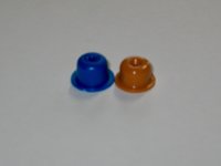
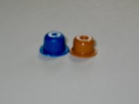
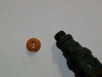
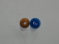
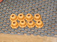
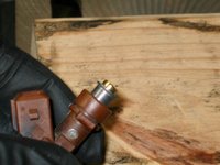
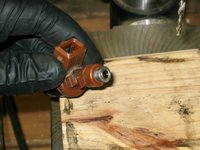
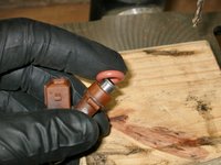
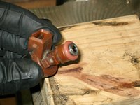
Before I get started on the fuel injector rebuild process, I wanted to do a quick comparison. Our member @a777fan (aka "Triple Trouble"), back in 2018 had sent me eight fuel injector pintle caps (aka "Smurf Hats") from the batch he had purchased as part of his own top-end rebuild. I had carefully squirreled these away in my basement parts stash, waiting for the day when I would use them.

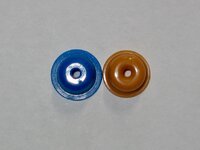
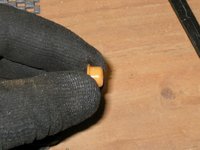
But, when I decided to get a full kit that had all fuel injector rebuild parts (new o-rings, spacers and filters), the kit came with its own set of brown Smurf Hats. The first few photos below are comparisons of these pintle caps. They are very close in size, although the brown hats are slighly (perhaps 1.5-2mm) shorter than the blue caps.
IMG_9283.jpeg IMG_9284.jpeg IMG_9285.jpeg


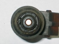
The holes in the middle of both Hats were the same diameter -- 5/64". This, obviously, was not going to be large enough to meet the needs of the factory pintle caps, which had a hole diameter of 5/32" -- a fair big larger.
IMG_9286.jpeg IMG_9287.jpeg IMG_9288.jpeg


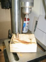
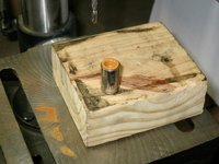
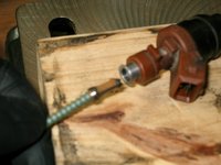
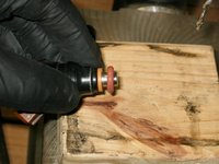
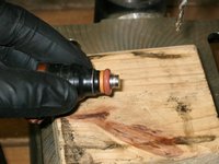
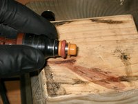
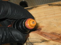
So, a solution to enlarge the holes in the pintle caps was needed. What I did was to take a 5/32" drill bit, and chuck it up in my bench-top drill press. I then put the pintle cap upside down inside of a 10mm 1/4" drive socket, and used that to hold the edges of the cap (wear gloves for this!) and drilled/enlarged the hole to make it the requisite size. Here are the steps involved.
IMG_9289.jpeg IMG_9290.jpeg IMG_9291.jpeg IMG_9292.jpeg


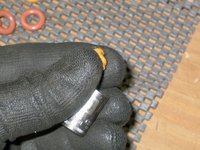
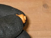
After drilling the hole, you will have a "pooched out" area where the drill bit exited the bottom of the pintle cap, like the two following photos show.
IMG_9293.jpeg IMG_9294.jpeg


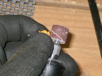
Some judicious and quick work with a Dremel sanding bit take care of this protrusion, and sands it down smoothly, as shown in the next photos.
IMG_9295.jpeg IMG_9296.jpeg


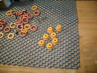
After doing the same thing eight times, you have the following.
IMG_9297.jpeg


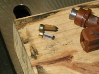
The next step is to remove the pressed-in filter. I used a large concrete screw -- screwed it about 1/3" into the end of the filter, and then wiggled it out with a rounded pulling motion. It comes out pretty easily, as long as you have a good enough "bite" on it with the screw.
IMG_9298.jpeg


Here's what the old filter looks like next to a new one.
IMG_9299.jpeg


Then it's time to insert a new filter into the top of the injector. I did this by pushing it in (first photo below) as far as I could with my fingers, and then tapping the top of the injector (the protruding part of the filter) onto the metal drill press base, until it was exactly flush with the top of the injector. It only takes 5-6 taps to go in all the way.
IMG_9300.jpeg IMG_9301.jpeg


After the filter is pressed in, then you can put one of the viton o-rings onto the top of the injector. It will look like the second photo, below.
IMG_9302.jpeg IMG_9303.jpeg


Finish rebuilding the bottom portion of the injector by inserting a spacer onto the tip, and then a second viton o-ring. Then you take your pintle cap, and press it on as far as you can with your fingers. A few taps on the end of the pintle cap on a hard surface (workbench or drill press base) will tap it all the way onto the injector, so it locks/snaps into place.
IMG_9304.jpeg IMG_9305.jpeg IMG_9306.jpeg IMG_9307.jpeg


And here you have a rebuilt injector. Rinse and repeat seven more times !!!
IMG_9308.jpeg
 
I decided to do another task before dinner -- replacing one of the two heater hoses. This hose was the one on the driver's side of the car, which goes through the inner firewall from the rear of the intake manifold to the heat exchanger pipe. There is also a small branch that goes off to the auxiliary water pump (IIRC).

Here is what the original hose looks like. The first clamp is easy to get at, from the area directly above the brake booster, and can be loosened with a 7mm socket, or a flat-blade screwdriver. It's your typical GEMI clamp.
IMG_9309.jpeg IMG_9310.jpeg


The first clamp has been loosened, and I used my hooked tool to work between the pipe and the hose, to loosen the end of the hose.
IMG_9311.jpeg IMG_9312.jpeg IMG_9313.jpeg


The next step is to loosen the smaller clamp, which sits underneath the edge of the water drain housing. It's difficult to get to, and you have to remove the lower section (a thin plastic plate, as shown in the third photo below) underneath the water drain housing / inner firewall area, to get to the clamp's bolt. The thin plastic plate is held to the inner firewall/water drain housing by two large Philips head bolts, and a 10mm plastic nut on the driver's side. Once you work it off and remove it, you can get behind it to get to the clamp bolt.
IMG_9314.jpeg IMG_9315.jpeg IMG_9316.jpeg


Loosening the second clamp, and removing the hose by threading the inner end through the firewall.
IMG_9317.jpeg IMG_9318.jpeg IMG_9319.jpeg


There's a removable round rubber grommet that protects the hose where it goes through the inner firewall.
IMG_9320.jpeg


Comparison of the old and new hoses. Although the old hose wasn't leaking or otherwise worn out, you can see that its ends were very compressed from the clamps, and after 25 years it was prudent to replace it. It's a difficult hose to get to if you don't remove the intake manifold -- you will never have a better opportunity to replace it then when you take the intake manifold out of the car.
IMG_9321.jpeg IMG_9322.jpeg IMG_9323.jpeg IMG_9324.jpeg IMG_9325.jpeg IMG_9326.jpeg


Sliding the firewall grommet back onto the new hose.
IMG_9327.jpeg


Working the new hose into place. It's not fun, nor easy, to work the stub of the hose onto the small aux water pump hose. I put a little lube on the end of the hose, and smeared a little lube inside the stub end of the hose, to facilitate sliding it on. This made it much easier. After attaching the stub and tightening the clamp, I then slid the large end of the hose onto the heat exchanger pipe, and tightened that clamp.
IMG_9328.jpeg IMG_9329.jpeg IMG_9330.jpeg


After both clamps were tight, I pressed the firewall grommet into proper position in the firewall, and this small portion of the job was complete.
IMG_9331.jpeg


I have the other heater hose, on the other side of the engine compartment, which I will replace as one of my next jobs.
 
Very nice write up, thx for that. That heater hose blew up on my car once on the highway, luckily noticed in time, shut down the motor and rolled until the next rest spot. Definitely time to replace all the coolant hoses (even the small or difficult to reach ones) after this time in service.
 
Very nice write up, thx for that. That heater hose blew up on my car once on the highway, luckily noticed in time, shut down the motor and rolled until the next rest spot. Definitely time to replace all the coolant hoses (even the small or difficult to reach ones) after this time in service.
Thanks. I know, I tell people all the time that these types of rubber items need to be replaced. This is the exact reason I'm doing it NOW. I know that heater hoses perhaps don't wear out as rapidly as the upper and lower radiator hoses, but they should nonetheless not be neglected. I am replacing every coolant hose underhood EXCEPT the upper radiator hose, which I replaced a few years back and is still in excellent condition. I think 25 years of service life is realistically all you can ask of a rubber coolant hose.
 
FYI:

When I was working on measuring and drilling out the pintle caps, I made some rough measurements and looked up what Triple Trouble (@a777fan) found with his digital calipers on his blue Smurf-Hat pintle caps, vs. the stock MB caps.

My pintle caps ordered from eBay, and the blue Smurf Hats had an identical rough measurement (using drill bits) of 5/64", or 1.98mm. @a777fan's measurement using digital calipers of 2.09mm.

My rough measurement of the stock MB black pintle cap was 5/32", or 3.96mm, as measured with a drill bit diameter. @a777fan's digital caliper measurement was 3.13mm.

I drilled (enlarged) my brown pintle cap holes with the 5/32" drill bit.

==========================

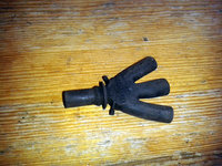
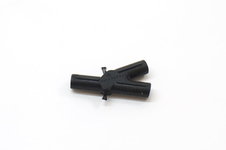
This morning, I decided to start a fourth parts order from MB of Annapolis. So far, I will be ordering a couple of vacuum connectors -- a 1-to-2-way connector, and a "crows-foot" one-to-three-way connector.

These connectors are illustrated below:

Crows-foot connector -- 201 805 02 22
s-l1600.zjpg.jpg


Y connector -- 601 078 02 45
601-078-02-45-MBZ.jpg


These connectors loosen over time and the vacuum line holes enlarge, leading to a gradual loss of effectiveness at holding vacuum. After 25 years, a good idea to replace these connectors, as well.
 
Is there a source for "correct" plastic pintle caps with 4mm holes?

:apl:
 

Who has viewed this thread (Total: 1) View details

Back
Top