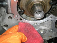
This afternoon, I spent about two hours out in the shop, and worked on replacing the two remaining timing chain slide rails on the left (driver's) side of the car.
Here's what unfolded over the afternoon.
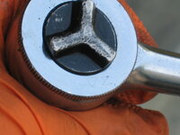
First, I used a Torx T-30 to tighten down the three bolts that hold the right-side exhaust cam sprocket to the cam. Then, I installed the plastic chain top guide, which fits between the two cam sprockets. The plastic is two parts that snap together, and are attached to the top of the cylinder head with two 5mm Allen bolts. I decided to re-use my top guide (despite having brand-new factory replacements), because their plastic was still flexible and nothing cracked. I had just replaced these top guides back in 2014, when I installed the metal cam oiler tubes. If you have not replaced these plastic top guides, I HIGHLY recommend that you do so. They are inexpensive to purchase from MB.

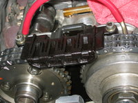
After finishing up the right (passenger) side, I turned my attention to the left (driver) side cams. As you probably remember, there are TWO plastic chain rails on this side of the cylinder head, both of which I wanted to replace. First, I removed the 5mm bolts that hold the top chain guide on the left side. Then I separated the guide's two pieces, and removed it.


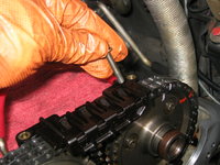

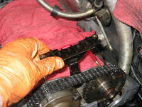
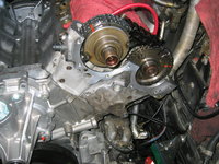
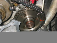
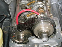
This exposed the cam sprockets and timing chain.

The next step was to remove the exhaust cam sprocket.
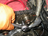
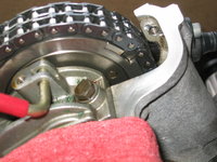

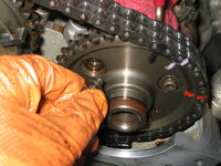

After loosening the sprocket, lift the timing chain off, and then you can remove the sprocket from the cylinder head.
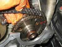
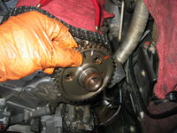
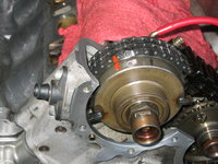
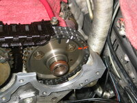
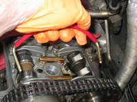
Removing the exhaust cam sprocket reveals the lower timing chain rail. Here are a couple of views of it.

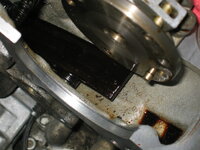
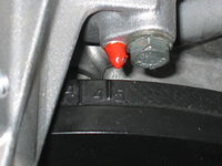
Also, here's a view of the exhaust cam, pinned with the crankshaft in the 45 degrees BTDC position.

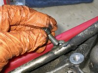
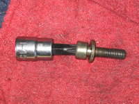
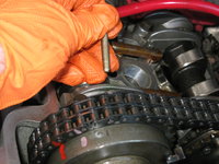
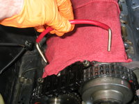
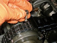
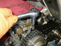
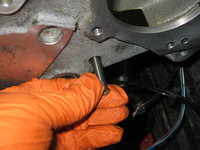
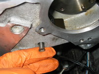
To remove the upper chain rail, screw in the timing chain pin puller into each pin, and then using two 14mm wrenches, remove the pin as shown below.
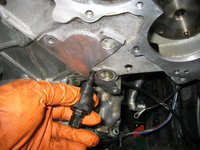
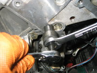

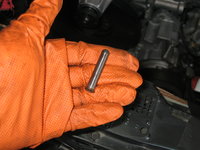
Removing the second pin that holds the lower rail in position.
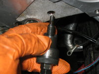
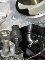
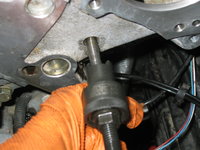

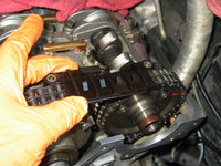
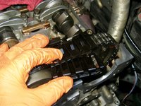
After removing both pins, carefully lift the rail out of the timing chain area.
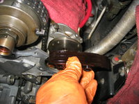

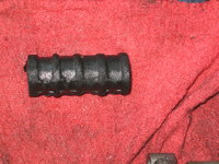
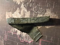
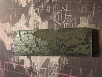
Shown in the sunlight, you can see only modest wear of the lower timing chain rail. It was not broken and had plenty of future wear left.
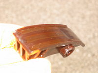
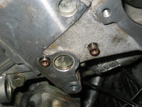
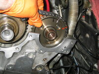
A couple of views of the exhaust cam area, with the lower timing chain rail removed.
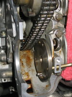

New rail and old rail, side by side. Installing the new lower rail is the reverse of the removal process.

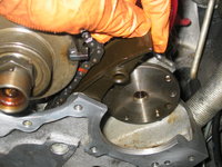

After replacing the lower rail, it's time to turn attention to the upper (inside) rail. Like with the right side, this requires disassembly and removal of the intake cam adjusting mechanism. Here is the process for removing it.
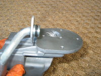
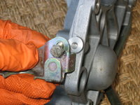
The first piece that needs to be removed is the armature. Because I will be replacing the cam solenoid, I also have to replace the armature (this is explained above). To remove the armature, pull it out slightly, and insert a Crescent wrench into the two parallel flat edges on the armature, to hold it.
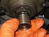
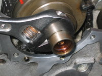
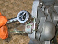
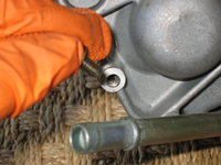
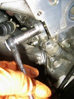
After you have a grip on the armature, take an 8mm socket and loosen the armature screw, while counter-holding the armature with the Crescent wrench. Pull the armature straight off of the adjusting mechanism, as shown in the third photo below.

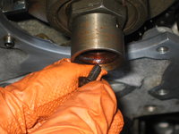
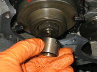
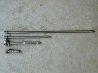
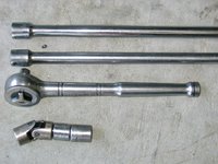
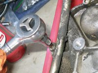
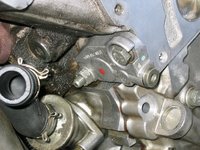
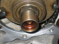
With the armature removed, you need to remove the adjuster mechanism itself. The large nut is 30mm, and I used a large impact socket to loosen it.
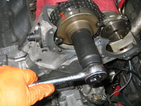
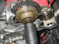

After removing the nut, take off the cap, as shown in the first photo below. Carefully lift the timing chain off of the sprocket, while holding the adjuster mechanism's sprocket in place -- it is under very strong spring tension. The second photo below shows the careful removal of the sprocket.
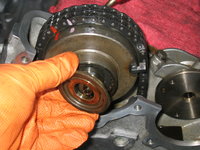

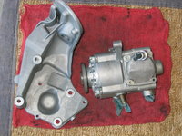
Remove the conically shaped spring. As noted before, the smaller end of the spring faces the cam. This is important for re-assembly.
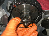
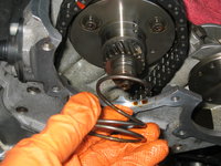
With the intake cam adjuster mechanism removed, you can see the upper chain rail. Here are a couple of views of it.
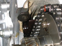
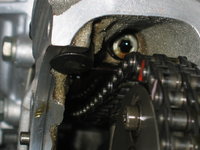
Here are the two pins that hold the upper rail in place. Removal of the two pins is the same process that you just did for the lower timing chain rail.


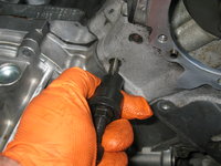
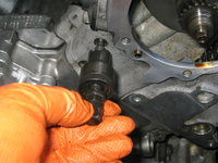
I had to use a pair of needle-nose pliers to grasp the old rail, and pull it free of the cylinder head.
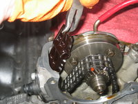

As you can see from the new rail beside it, the old rail was completely intact, and not horribly worn. It had some life left in it.

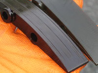
The new rail installation is the exact reverse of removal.

Here is a view of the new rail in place, and re-installing the two pins.


Chase heartily approved of the work I was doing.

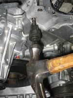

A view of the new rail, installed and in place.
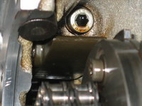
The next step is to re-install the intake cam adjustment mechanism. Get the timing chain out of the way. Then install the conical spring.
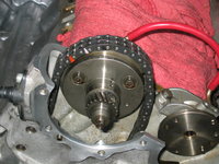

Take apart the two pieces of the sprocket mechanism.


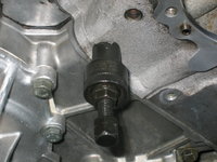
Using the flat spot as a guide, install the rear-most part of the sprocket mechanism. There is only one way it can install, but it is difficult due to the strong tension provided by the conical spring. In the first photo below, I am holding the rear-most sprocket piece in place with the heel of my left hand. Using my right hand, I screwed the "pressure nut" (the MB special tool) into place to hold the rear-most sprocket piece in place against the conical spring's tension. The second and third photos below show the pressure nut in place.


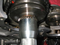
The next step is to install the front-most piece, which again only installs one way onto the rear-most piece. The pressure-nut tool allows you to slide the front-piece over it to mate it up with the rear piece, as shown in the second photo below.
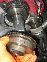
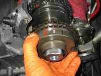
Once you have the front-piece in place, place the timing chain over it in the proper, marked position. Gradually loosen the pressure nut, while holding the intake cam sprockets together. The timing chain will also help keep things in place. Looking at the back of the sprocket mechanism, you want to make sure it is assembled in the "retard" position, as shown with the flange in the slot in the first photo below.
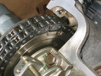

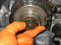
Remove the pressure nut while holding things together. Install the cap, as shown in the first two photos below. Then install the nut, making sure that the split in the nut is toward the front (facing you). Snug the nut down.
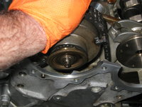

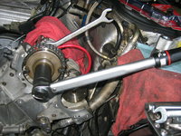
Torque the nut down, using a torque wrench, to the specified 65 Nm.

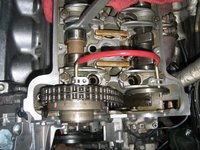
An overview of the assembled intake cam adjuster mechanism, showing the pinned cams.
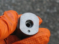
Get out the new armature, noting (as in the second and third photos below), the flat spot in the armature and on the end of the intake cam adjuster. The armature will only press on in one orientation.



Snug the armature screw down. Using the Crescent wrench, tighten it down. I believe MB specifies 7 Nm as the torque. I probably tightened it down slightly more than that. MB also specifies that a new screw be used, and that the old screw NOT be re-used.
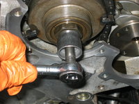
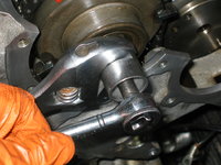
A view of the tightened-down armature and intake cam adjuster mechanism.
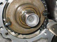
The last step is to re-install the exhaust cam sprocket. This is a pretty straightforward operation, though I stopped working right at this point in time.
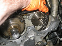
Thanks for your interest!
Cheers,
Gerry


