• Hi Guest !

    Welcome to the 500Eboard forum.

    Since its founding in late 2008, 500Eboard has become the leading resource on the Internet for all things related to the Mercedes-Benz 500E and E500. In recent years, we have also expanded to include the 400E and E420 models, which are directly related to the 500E/E500.

    We invite you to browse and take advantage of the information and resources here on the site. If you find helpful information, please register for full membership, and you'll find even more resources available. Feel free to ask questions, and make liberal use of the "Search" function to find answers.

    We hope you will become an active contributor to the community!

    Sincerely,
    500Eboard Management

RESTO PROJECT: M119 / W124 / E500 Engine Top-End Refresh

Hi JC,

Yes, I can get a socket on that remaining 13mm bolt that holds the bracket to the cylinder head, using a wobbly and a couple of long extensions. It seems that it is just a bit of an extreme angle with the wobbly, so I guess I'm going to have to find another shallower angle so that I can get more torque on the bolt head.

Also, my 3/8" 13mm socket is a 12-point, which makes it much more difficult to get a purchase on that bolt head. I'm going to use a reducer adapter to go down from 3/8" drive to 1/4" drive (maintaining my 3/8" ratchet and extensions), as my 1/4" socket in 13mm is a six-point head, which will give a more sure-fit on that bolt head.

As you can see, I'm already plotting out my plan of attack :)

Thanks much for the input :lightning:
 
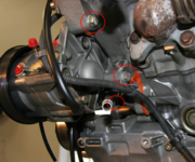
Gerry, is it the top bolt giving you trouble? The 3 culprits are circled in red below:

1594650007387.png
 
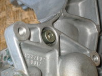
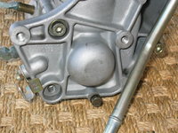
No, it's the middle bolt in the photo. The top-most one I actually was able to get from the FRONT of the engine.

The bottom bolt I believe is accessed from the FRONT of the plate, underneath the power steering reservoir. Your photo is showing a bolt that is accessed from behind the plate, but I don't think that is correct -- that lower bolt is a 6mm Allen that's accessed (as shown above in my latest photo essay) from the front of the engine).

I know for sure that there are only three bolts that hold the bracket to the engine, because I can swivel the entire plate + tandem pump assembly about 1/2 inch back and forth along an axis. Which means it is only being held by ONE bolt. If the bracket was being held by two bolts (two different physical locations), I would not be able to move it back and forth.
 
Last edited:
Back in stock .... but just barely. You have to check every single day.


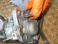
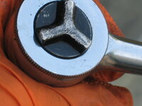
By the way, I did go through a couple of orange gloves yesterday in the course of my wrenching, but these gloves had been re-used at least two times (including at the wrecking yard), and the holes were "pinhole" type holes caused by pinching when tightening fasteners ... not catastrophic "rip" or "split" type failures that you normally find with gloves.
Already sold out again! Grrr. I'd like to try a box (L) for grins some day. The black 6-mil are also sold out.
 
No, it's the middle bolt in the photo. The top-most one I actually was able to get from the FRONT of the engine.

The bottom bolt I believe is accessed from the FRONT of the plate, underneath the power steering reservoir. Your photo is showing a bolt that is accessed from behind the plate, but I don't think that is correct -- that lower bolt is a 6mm Allen that's accessed (as shown above in my latest photo essay) from the front of the engine).

I know for sure that there are only three bolts that hold the bracket to the engine, because I can swivel the entire plate + tandem pump assembly about 1/2 inch back and forth along an axis. Which means it is only being held by ONE bolt.
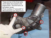
There are 3 bolts which attach the bracket to the block, from the back side.

There is a 4th bolt near the top accessed from the front, just below the reservoir return pipe, this one is easy to remove.

1594650846469.png
 
I'm not sure why I can swivel the reservoir + bracket assembly then. With two bolts in place, the bracket should NOT be able to swivel back and forth.

I have only removed TWO bracket bolts -- one being the right-most one in your @emerydc8 photo above (front side, under the reservoir), and the left-most one with the finger point to it directly underneath the word bubble.
 
It's possible the photos may be incorrect... I didn't pay that much attention last time I did this job. If so, I'll update / edit the photos & captions.

Alternately, it's also possible a previous mechanic left one of the bolts out, figuring 3 was adequate!

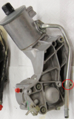
EDIT: Only 3 bolts attach the bracket to the head. The bottom bolt in the photo attaches the metal pipe. I'll need to update the photos and captions.

:facepalm: :doh: :jelmerian: :doof:

1594654619328.png
 
Last edited:
I don't recall removing a bolt from the back (other than the two TANDEM PUMP hex bolts) when I did my tandem pump remove job; and I don't think any other mechanic has been in there since I got the car (or before ... it had 58K on it when I bought it).

I'll focus on that middle bolt, and if it comes out, then I'm good. I'll do some exploring in there as to the bottom-most bolt you indicate.
 
EDIT: Only 3 bolts attach the bracket to the head. The bottom bolt in the photo attaches the metal pipe. I'll need to update the photos and captions.

:facepalm: :doh: :jelmerian: :doof:

View attachment 107266
Meh, no @Jelmerian required for that one.

Cool, I was REALLY scratching my head over it though, because the bracket's "swivel" don't lie....

I'm going to go out to the shop and try to attack it again during my lunch break.
 
I spent exactly two hours out in the shop this afternoon, from 3-5 PM, trying to take a bit of time off of work.

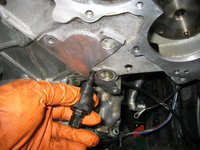
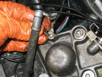
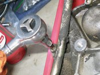
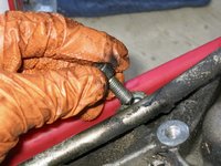
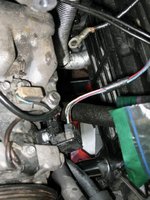
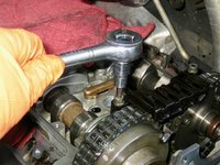
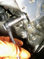
I am happy to say that I was successful at removing that final bolt that held the tandem pump mounting bracket onto the back of the cylinder head. You'll see what I used to do it, in a minute. Suffice it to say that @JC220's comment got me thinking a bit harder about the "angle" that I needed to use to get proper leverage on that final 13mm bolt. Not only did the six-point socket help, but I was able to make the angle MUCH shallower by routing the socket and extensions aft of the reinforcing bar under the car. This immediately allowed me to loosen that bolt, and in just a minute or so, it was out.


After removing the final bolt and loosening the mounting plate, all I had to do (as in the photo below) was to loosen and remove the 10mm bolt that held a ground wire to the bottom of the mouting plate.
IMG_9812.jpeg


Lifting the tandem pump and bracket assembly out of the engine compartment . . . . .
IMG_9813.jpeg


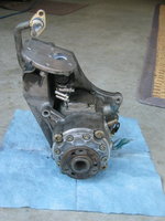
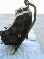
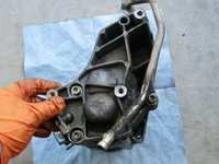
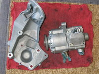
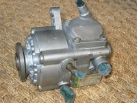
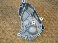
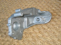
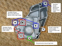
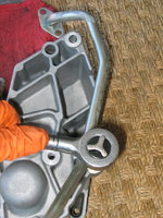
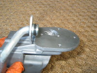
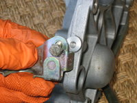
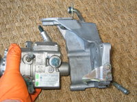
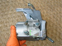
And a few views of it (obverse and reverse) out of the car. The third photo shows clearly the three mounting bolts for the bracket -- the first one is between my pinched fingers; the second one is just to the left of the vertical power steering pipe (this is the one I had difficulty removing); and the third one is at the top of the photo, right of center.
IMG_9814.jpeg IMG_9815.jpeg IMG_9816.jpeg


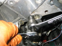
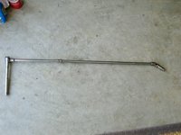
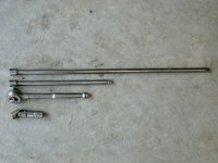
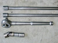
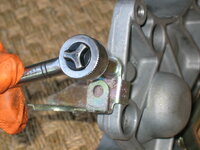
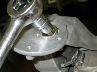
Here is the "getup" that I used to remove the remaining bolt for the bracket: one 3/8" ratchet; one medium-long extension; one long-long extension; one 3/8" "wobbly" joint; one 3/8" to 1/4" drive converter; and one 1/4" drive, six-point 13mm socket. WHEW!
IMG_9817.jpeg IMG_9818.jpeg IMG_9819.jpeg IMG_9820.jpeg


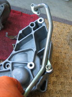
After removing the assembly, it was time to disassemble it. First, the 6mm Allen bolt that held the power steering pipe to the back of the bracket.
IMG_9821.jpeg IMG_9822.jpeg


Then, the 8mm bolt that held the clamp for the power steering high-pressure hose in place.
IMG_9823.jpeg


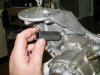
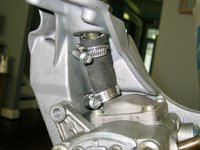
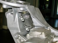
Here is a view of my "short hose" for the power steering reservoir to the pump. You can see the indentations from the FOUR ring clamps that I used. The hose honestly only after 5-6 years was pretty beat-up, so I am going to replace it with a new length of hose. Haven't decided whether I will go back to two clamps, or use four clamps.
IMG_9825.jpeg


Next, it was time to remove the tandem pump from the mounting bracket. Easy peasy, right? Seeing as there were only TWO 6mm hex bolts holding the pump to the bracket, it would be an easy job. Well, closer examination of the two bolts showed that the head of one of them was pretty much stripped (probably from my attempts to remove it yesterday, as well as my prior attempts when I removed the tandem pump to refurbish it some years back), while the other bolt showed some wear, but was serviceable enough.

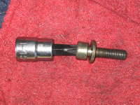
The serviceable bolt came out OK, but the other one (as expected) stripped out. I was able to drive a Torx T-45 socket into it, and this gave me enough of a "bite" so that I could turn it out. You can see it below in the second photo.
IMG_9826.jpeg IMG_9827.jpeg


Then I proceeded to soak the parts, and plug the holes in the tandem pump to prepare it for cleaning. Everything will be nicely cleaned up in time for re-assembly. Fortunately, I had put two replacement bolts on my MB parts order this morning, so I should have the two 6mm hex mounting bolts for the tandem pump later this week.


Here are a couple of views of the left-side of the engine, with the tandem pump and bracket removed.
IMG_9828.jpeg IMG_9831.jpeg


And here are a couple of views of the camshafts on the left-side, both pinned and marked, and almost ready for disassembly and installation of the new armature.
IMG_9829.jpeg IMG_9830.jpeg


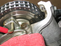
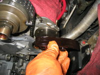
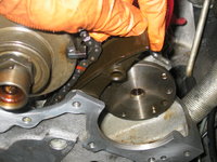
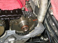
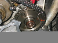
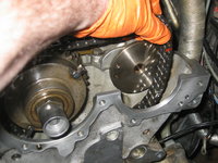
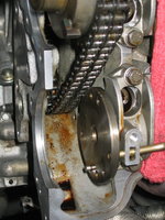
In the photo below, you can see the four holes that hold the pins for the two timing chain rails -- the vertical pair of dark holes on the left side of the photo, and the corresponding pair on the right side of the photo. It is this right-side pair of pins that were covered up by the tandem pump mounting bracket, and exposing them (for chain rail replacement) was the ENTIRE goal of this tandem pump + bracket removal exercise. Well ... that and cleaning up the area more completely ;)
IMG_9832.jpeg


A close-up view of the tandem pump and A/C compressor area show that there is a lot of insulation and covering worn off of the wires, due to heat and age, so all of this is going to be replaced as part of the process.
IMG_9833.jpeg


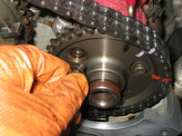
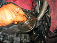
The last thing I did for the day, was to begin re-assembling the right-side (passenger) side of the cams. Mainly, this was just re-attaching the right-side exhaust cam sprocket, and ensuring that the lines I'd made lined up. There is a small dowel on the end of the cam that lines up with a hole in the sprocket, and then it is just a matter of lining up the cam's threaded holes with the sprocket's holes, and screwing in the three small cam sprocket bolts. I'll tighten them up tomorrow as my next step.
IMG_9834.jpegIMG_9835.jpeg IMG_9836.jpeg

NOTE: As you look at the first photo in the pair above, you see that the orange mark is lining up, and the pink marks are NOT lining up. I had made the pink mark as a reference mark earlier, when the chain skipped two teeth, so I knew where it had skipped TO. The orange mark I made after I got the cam and chain back into the correct position, and this is the proper reference mark for re-assembly. Also note the very faint black "arrow" that I made with a Sharpie marker, to remind myself which direction I needed to rotate the cam and sprocket so that I could get things properly corrected.
 
Last edited:
This morning I took about an hour to clean the tandem pump (which was surprisingly dirty) and the bracket, and the associated hardware. Then I re-assembled everything, and set it aside for re-installation into the car once I complete the driver's side timing chain rail replacement, and cleaning and refurbishing of the A/C compressor wiring, and lower cylinder head area on the left side.

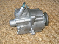
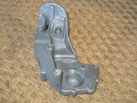
Here are some very clear views of the pump, bracket, and hardware for reference. @gsxr, you may want to take the bracket photo with the holes I've identified, for reference on your web site.

First, a view of the cleaned-up bracket and pump, immediately after the cleaning process. This took about 45 minutes to soak the bracket and clean it with a brush, and then clean the exterior of the pump, as well. Those are pieces of lint-free towels in the four hose connections on the tandem pump, so that no dirt or debris enters the pump.
IMG_9801.jpeg


A couple of views of the tandem pump.
IMG_9802.jpeg IMG_9803.jpeg


A few views of the tandem pump bracket.
IMG_9804.jpeg IMG_9805.jpeg IMG_9806.jpeg IMG_9807.jpeg


Gathering the items required to re-assemble the pump and bracket. Note that the power steering metal pipe, hose bracket and associated hardware were also cleaned.
IMG_9808.jpeg


Attaching and tightening the power steering fluid return hose to the back of the bracket, with a single 6mm bolt.
IMG_9809.jpeg IMG_9810.jpeg IMG_9811.jpeg IMG_9812.jpeg IMG_9813.jpeg


Here's what the end of the hose looks like, where it bolts onto the back of the power steering reservoir. Note that I had replaced the black rubber o-ring some years back when I serviced the tandem pump, and it still maintains plenty of shape and flexibility, so I am leaving it alone this go-round.
IMG_9814.jpeg


View of the hose attached to the tandem pump mounting bracket.
IMG_9815.jpeg


Next it was time to attach the power steering high-pressure hose bracket to the tandem pump bracket. This is held on with a single 10mm bolt, and tightened into place. There is a flange that rests against the tandem pump bracket to ensure that the hose bracket is in proper position.
IMG_9816.jpeg IMG_9817.jpeg


The next thing I did was to install, for safe-keeping purposes, the small 8mm bolt that connects the ground connector wire to the bottom of the tandem pump mounting bracket. This will be the very last thing I connect, after I re-mount the tandem pump and bracket onto the engine. I left it loose so that I can easily turn it out when needed. This bolt is very easy to access from underneath the car, with the "S" hose and driver's side motor mount cooling pipe removed from the car.
IMG_9818.jpeg IMG_9819.jpeg


The last step for the morning was the re-attach the tandem pump to its mounting bracket. It only fits one way so it's a very simple operation. Seeing that I only had one of the two 6mm Allen-head mounting bolts available that attach the pump to the bracket from the rear side (remember that I'd stripped the other one trying to remove it; and I should be receiving the new factory bolt in today's MB Annapolis parts order), I went ahead and installed it, and will add the second rear mounting bolt when I get it. The third and fourth pump mounting bolts will be added when the pump and bracket are properly mounted onto the engine, at a later time.
IMG_9820.jpeg IMG_9821.jpeg IMG_9822.jpeg IMG_9823.jpeg


Here is the top-most tandem pump mounting bolt in position. The lower one will be added upon receipt.
IMG_9824.jpeg IMG_9825.jpeg


And for now, that is all. Happy to have the pump and bracket setup cleaned, prepped, and ready for a hasty re-installation !!

Cheers,
Gerry
 
Last edited:
Looks great, Gerry! Thanks for the annotated image with the mounting holes identified - I'm sure this will help a lot of people in the future.

:love:
 
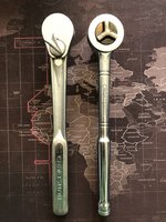
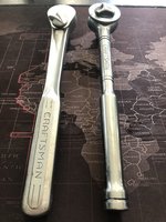
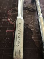
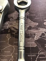
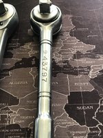
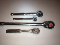
It's a Craftsman ratchet (part of a set of three -- 1/2", 3/8" and 1/4") that my parents gave me while I was in college, in the late 1980s, as part of many years of tools they gifted me for birthdays and Christmas presents. Fortunately it was a USA-made ratchet, before Craftsman began off-shoring their tool production in more recent years.

A couple of summers ago, I scored my Dad's set of Craftsman ratchets, vintage 1960s. These ratchets hold a special place of honor in my tool workbench.

And you can still get rebuild kits for most of them on eBay. I have all of my Dad's Craftsman tools I still use today, and got rebuild kits for all of the ratchets as Christmas presents. Considering that they're easily 50-60 years old, we've definitely gotten our money's worth out of them. To be able to rebuild them could potentially extend their lives another 50+ years as well.

Dan
Old school (1960s) on the left.
Newer school (1980s) on the right.


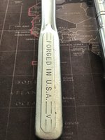
The 1960s ratchet of my Dad's has the "V" on it, meaning it is a genuine early-1960s item. My Dad got this set probably about the year my older sister was born. I'll have to ask my mom, but it was probably part of a set of tools she got him as a Christmas present or something.

59632DD2-9C87-4D19-8F57-641B49F299F7.jpeg 14BA034C-0D9E-4929-BE8A-9A3CF48711B0.jpeg 0FF769A6-AB65-4929-A77A-0DB58AB73C74.jpeg C134E6C5-3703-4AA3-A73E-02FE5D9DB906.jpeg 1F1C2105-F3D6-4545-8CCA-7B97097F59EE.jpeg 9C2B7E83-5DF2-4B0F-A1B5-6A7B920E3695.jpeg
 
Last edited:
We have the same ratchets.

1594922981110.jpeg

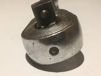
Gerry you didn’t point out the cool feature of that ‘V’ ratchet which is that it has its own spring loaded oil fill chamber.

1594923152346.jpeg

I remember getting a 300 piece set at Sears in 1992 for $300. I was never a mechanic (still not:LOL:) but it was apparent that I was running out of tools for the jobs I was getting into. A dollar a tool seemed like a good deal considering what one visit to the Snap On truck cost me.
Most of this 300 pc set Is still around and I better not lose any more as I lost 2 extensions a year ago and was catatonic for a week until I admitted that they’re gone for good.

I have a couple of more vintage ratchets in addition to these and realize that I might be turning into a small time vintage tool collector.

The SnapOn ratchet in the picture belonged to my uncle who had a shop for a few decades beginning in the 60s. It’s a 1976 date code and while he’s no longer around I like knowing that it’s still being used by a family member.

You’re doing a lot of good work.
I thought you were going to beat me on this project but we’re close. I’m waiting for what should be the last few parts from the dealer which should be next week.
 
The good thing is that appropriate replacements are available easily on eBay (used) from the era that your tools are from.

With my own tools that I got as gifts, I inscribed every socket, ratchet, extension and the like with my initials back when I got them (I think it was probably a set as a Christmas present from my parents, around 1987). The tools all came in a huge black metal Craftsman tool box, and I carried that tool box (secured with a bungie cord) in the back of my 1984 VW Rabbit GTI for years until I sold it to a friend in 1992. I think I still have the tool box sitting in my basement, too.

My mom (who turned 82 in May) told me yesterday that she didn't remember ever buying my dad a large set of Craftsman tools, as they just didn't have that much money back in 1962 or so (my dad had just gotten out of the Army, and had taken a job with Weyerhaeuser Co. in Tacoma...the only company he ever worked for). She said that buying a set of tools like that for $150-200 back then would have been a month's salary! So she thinks either her dad (my grandpa) gave both of them some money as a present, or that my dad bought small sets of tools and assembled them piecemeal over time. She said they didn't really have ANY tools when they were in the Army from 1960-62, because they rented a house and didn't need them), so my Dad would have started buying tools after they bought their Tacoma (Lakewood) house in 1962-1963 because he would have needed them to repair things around the house. Anyway, the "V" ratchets are definitely early-mid-60s vintage and are very high quality. I remember using them all the years I grew up to fix my bikes, skateboards, etc. I love the memories with those old-school Craftsman tools.

Damn it, all this talk makes me think of my Dad again. It's been almost 5 years since he died.
 
This afternoon, I spent about two hours out in the shop, and worked on replacing the two remaining timing chain slide rails on the left (driver's) side of the car.

Here's what unfolded over the afternoon.

First, I used a Torx T-30 to tighten down the three bolts that hold the right-side exhaust cam sprocket to the cam. Then, I installed the plastic chain top guide, which fits between the two cam sprockets. The plastic is two parts that snap together, and are attached to the top of the cylinder head with two 5mm Allen bolts. I decided to re-use my top guide (despite having brand-new factory replacements), because their plastic was still flexible and nothing cracked. I had just replaced these top guides back in 2014, when I installed the metal cam oiler tubes. If you have not replaced these plastic top guides, I HIGHLY recommend that you do so. They are inexpensive to purchase from MB.
IMG_9826.jpeg IMG_9827.jpeg


After finishing up the right (passenger) side, I turned my attention to the left (driver) side cams. As you probably remember, there are TWO plastic chain rails on this side of the cylinder head, both of which I wanted to replace. First, I removed the 5mm bolts that hold the top chain guide on the left side. Then I separated the guide's two pieces, and removed it.
IMG_9828.jpeg IMG_9829.jpeg IMG_9830.jpeg IMG_9831.jpeg IMG_9832.jpeg


This exposed the cam sprockets and timing chain.
IMG_9833.jpeg


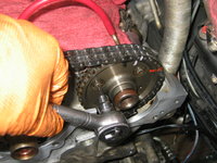
The next step was to remove the exhaust cam sprocket.
IMG_9834.jpeg IMG_9835.jpeg IMG_9837.jpeg IMG_9838.jpeg IMG_9839.jpeg


After loosening the sprocket, lift the timing chain off, and then you can remove the sprocket from the cylinder head.
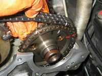
IMG_9840.jpeg IMG_9841.jpeg


Removing the exhaust cam sprocket reveals the lower timing chain rail. Here are a couple of views of it.
IMG_9842.jpeg IMG_9843.jpeg


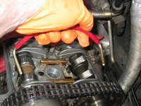
Also, here's a view of the exhaust cam, pinned with the crankshaft in the 45 degrees BTDC position.
IMG_9844.jpeg


To remove the upper chain rail, screw in the timing chain pin puller into each pin, and then using two 14mm wrenches, remove the pin as shown below.
IMG_9845.jpeg IMG_9846.jpeg IMG_9847.jpeg IMG_9848.jpeg


Removing the second pin that holds the lower rail in position.
IMG_9849.jpeg IMG_9850.jpeg IMG_9851.jpeg IMG_9852.jpeg


After removing both pins, carefully lift the rail out of the timing chain area.
IMG_9853.jpeg IMG_9854.jpeg


Shown in the sunlight, you can see only modest wear of the lower timing chain rail. It was not broken and had plenty of future wear left.
IMG_9855.jpeg


A couple of views of the exhaust cam area, with the lower timing chain rail removed.
IMG_9857.jpeg IMG_9858.jpeg


New rail and old rail, side by side. Installing the new lower rail is the reverse of the removal process.
IMG_9859.jpeg IMG_9860.jpeg IMG_9861.jpeg IMG_9862.jpeg IMG_9863.jpeg IMG_9864.jpeg


After replacing the lower rail, it's time to turn attention to the upper (inside) rail. Like with the right side, this requires disassembly and removal of the intake cam adjusting mechanism. Here is the process for removing it.

The first piece that needs to be removed is the armature. Because I will be replacing the cam solenoid, I also have to replace the armature (this is explained above). To remove the armature, pull it out slightly, and insert a Crescent wrench into the two parallel flat edges on the armature, to hold it.
IMG_9865.jpeg IMG_9866.jpeg IMG_9867.jpeg


After you have a grip on the armature, take an 8mm socket and loosen the armature screw, while counter-holding the armature with the Crescent wrench. Pull the armature straight off of the adjusting mechanism, as shown in the third photo below.
IMG_9868.jpeg IMG_9869.jpeg IMG_9870.jpeg


With the armature removed, you need to remove the adjuster mechanism itself. The large nut is 30mm, and I used a large impact socket to loosen it.
IMG_9872.jpeg IMG_9873.jpeg IMG_9874.jpeg


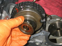
After removing the nut, take off the cap, as shown in the first photo below. Carefully lift the timing chain off of the sprocket, while holding the adjuster mechanism's sprocket in place -- it is under very strong spring tension. The second photo below shows the careful removal of the sprocket.
IMG_9875.jpeg IMG_9876.jpeg


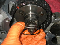
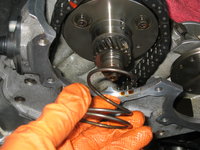
Remove the conically shaped spring. As noted before, the smaller end of the spring faces the cam. This is important for re-assembly.
IMG_9877.jpeg IMG_9878.jpeg


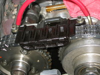
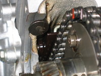
With the intake cam adjuster mechanism removed, you can see the upper chain rail. Here are a couple of views of it.
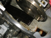
IMG_9879.jpeg IMG_9880.jpeg


Here are the two pins that hold the upper rail in place. Removal of the two pins is the same process that you just did for the lower timing chain rail.
IMG_9881.jpeg IMG_9882.jpeg IMG_9883.jpeg IMG_9884.jpeg IMG_9885.jpeg


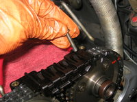
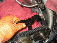
I had to use a pair of needle-nose pliers to grasp the old rail, and pull it free of the cylinder head.
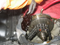
IMG_9886.jpeg IMG_9887.jpeg


As you can see from the new rail beside it, the old rail was completely intact, and not horribly worn. It had some life left in it.
IMG_9888.jpeg IMG_9889.jpeg


The new rail installation is the exact reverse of removal.
IMG_9890.jpeg


Here is a view of the new rail in place, and re-installing the two pins.
IMG_9891.jpeg IMG_9892.jpeg


Chase heartily approved of the work I was doing.

IMG_9893.jpeg IMG_9894.jpeg IMG_9895.jpeg


A view of the new rail, installed and in place.
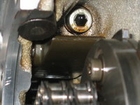
IMG_9896.jpeg


The next step is to re-install the intake cam adjustment mechanism. Get the timing chain out of the way. Then install the conical spring.
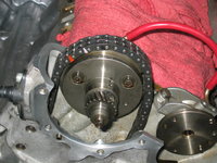
IMG_9897.jpeg IMG_9898.jpeg


Take apart the two pieces of the sprocket mechanism.
IMG_9899.jpeg IMG_9900.jpeg


Using the flat spot as a guide, install the rear-most part of the sprocket mechanism. There is only one way it can install, but it is difficult due to the strong tension provided by the conical spring. In the first photo below, I am holding the rear-most sprocket piece in place with the heel of my left hand. Using my right hand, I screwed the "pressure nut" (the MB special tool) into place to hold the rear-most sprocket piece in place against the conical spring's tension. The second and third photos below show the pressure nut in place.
IMG_0001.jpeg IMG_0002.jpeg IMG_0003.jpeg


The next step is to install the front-most piece, which again only installs one way onto the rear-most piece. The pressure-nut tool allows you to slide the front-piece over it to mate it up with the rear piece, as shown in the second photo below.
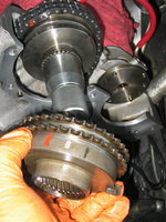
IMG_0004.jpeg IMG_0005.jpeg


Once you have the front-piece in place, place the timing chain over it in the proper, marked position. Gradually loosen the pressure nut, while holding the intake cam sprockets together. The timing chain will also help keep things in place. Looking at the back of the sprocket mechanism, you want to make sure it is assembled in the "retard" position, as shown with the flange in the slot in the first photo below.
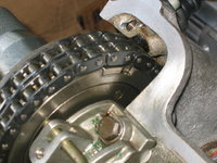
IMG_0006.jpeg IMG_0007.jpeg


Remove the pressure nut while holding things together. Install the cap, as shown in the first two photos below. Then install the nut, making sure that the split in the nut is toward the front (facing you). Snug the nut down.
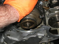
IMG_0008.jpeg IMG_0009.jpeg IMG_0010.jpeg


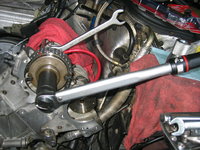
Torque the nut down, using a torque wrench, to the specified 65 Nm.
IMG_0011.jpeg IMG_0012.jpeg


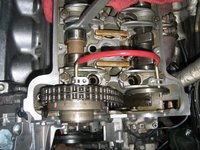
An overview of the assembled intake cam adjuster mechanism, showing the pinned cams.
IMG_0013.jpeg


Get out the new armature, noting (as in the second and third photos below), the flat spot in the armature and on the end of the intake cam adjuster. The armature will only press on in one orientation.
IMG_0014.jpeg IMG_0015.jpeg IMG_0016.jpeg IMG_0017.jpeg


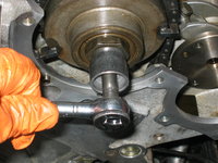
Snug the armature screw down. Using the Crescent wrench, tighten it down. I believe MB specifies 7 Nm as the torque. I probably tightened it down slightly more than that. MB also specifies that a new screw be used, and that the old screw NOT be re-used.
IMG_0018.jpeg IMG_0019.jpeg


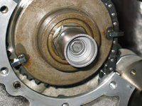
A view of the tightened-down armature and intake cam adjuster mechanism.
IMG_0020.jpeg


The last step is to re-install the exhaust cam sprocket. This is a pretty straightforward operation, though I stopped working right at this point in time.
IMG_0021.jpeg IMG_0022.jpeg


Thanks for your interest!

Cheers,
Gerry
 
With my own tools that I got as gifts, I inscribed every socket, ratchet, extension and the like with my initials back when I got them (I think it was probably a set as a Christmas present from my parents, around 1987).
Here's a view of the inscription of my initials on one of the Craftsman ratchets. I probably did this in 1987 or 1988.

IMG_9871.jpeg
 
Just got the intake manifold parts back today.

As well as a case of Chlorinated Brake Cleaner from NAPA Auto Parts -- $3.00 a can !!! Load up while it's half price
I happened to stop by my local AutoZone store today, to get some Lucas Assembly Lube, and a new tube of blue Permatex threadlocker gel.

I noticed that AZ was having a sale on CRC Chlorinated brake cleaner (red can) -- 2 cans for $7.00 ... that's $3.50 a can, or about $2-2.50 off normal price per can!! So I picked up another case, seeing as I'd gone through 8 or 9 of the cans from the previous case I'd bought.

More engine cleaning to do...

I buy the stuff from Advance Auto all the time for around that much ($3.75/can). Order it online for pickup at the store and use "COUPON25" to get 25% off. That's a good deal if it's the tall cans.

Dan
 
If you don't have the good red-can stuff available locally, Zoro carries it. They periodically have sales at 15-25% off which can drop the price under $3/can, free shipping on orders over $50. They carry Zerex G-05 as well.

 
Little bit of work Saturday and Sunday. It was 90+F outside, and with the heat index well over 100F, so I took it easy and didn't spend too many hours out in the shop. I'd say a total of about three hours between Saturday and Sunday.

Picking up where I left off, I secured the three bolts that hold the left-side exhaust cam sprocket to the camshaft, and tightened them appropriately with the Torx T-30 socket.
IMG_0023.jpeg


All lined up, and everything looks pretty good. Here's what the indicator showed throughout the entire operation, with all four cams pinned. About 1-1.5 degrees off the mark, with 142K miles on the chain. I can't complain.
IMG_0024.jpeg


I removed the pins from the intake and exhaust cams. First on the left side .....
IMG_0025.jpeg IMG_0026.jpeg


... And then on the right side.
IMG_0027.jpeg


Then it was time to re-install the timing chain top guide on the left side. Pretty simple: insert piece; align; install second piece; snap into place; and insert/tighten 5mm Allen bolts.
IMG_0028.jpeg IMG_0029.jpeg IMG_0030.jpeg IMG_0031.jpeg IMG_0032.jpeg IMG_0033.jpeg


Next up was the timing chain tensioner. I decided (despite having a spare, new tensioner), to re-use the original tensioner, as it seemed in good condition. I did, per the factory service manual, install a new timing chain tensioner gasket. Pretty simple operation, as well -- tighten the 13mm bolt, and the 13mm nut and washer, evenly and to a torque of 25 Nm. The last photo shows that I still have some cleaning to do on the underside of the cylinder head -- this schmutz is likely due to the small valve cover leak that I had previously.
IMG_0034.jpeg IMG_0035.jpeg IMG_0036.jpeg


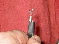
Next up was a small restoration job -- the sheathing around the A/C compressor wires (where it connects to the compressor, going to the driver's side wheel well area near the EZL, was TOTALLY gone. So, I decided to install new sheathing on the three wires. This ended up being a bit more of a PITA than I thought it was going to be, for reasons you'll see in a minute.

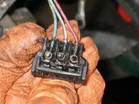
First, though, here is the connector. Because it was a few inches from the engine, on the top of the A/C compressor, it was not exposed to the engine heat like many other connectors are, and so it was still quite supple and totally intact. I would have replaced it (I have extra connector pin bushing housings of this right-angle type), but it did not need to be replaced !! It was quite dirty, and I cleaned it up with some brake cleaner. Here are a few views of the connector and wires as they came off of the top of the compressor.
IMG_0038.jpeg IMG_0039.jpeg IMG_0040.jpeg


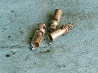
And, the wires and their pin bushing housings, removed from the connector.
IMG_0041.jpeg


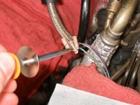
Because the three pin bushing housings were too large for the heat-shrink wire sheathing I have, I had to use a soldering iron to remove each of the pin bushing housings from the ends of the wires. I did this, as below in the photos.
IMG_0042.jpeg IMG_0043.jpeg IMG_0044.jpeg IMG_0045.jpeg


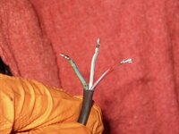
With the wires exposed, I could insert them, as shown below, into the proper length of heat-shrink sheathing.
IMG_0046.jpeg IMG_0047.jpeg


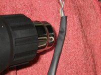
Using my heat gun, I then "shrunk" the sheathing around the three wires. The second photo shows what things looked like -- I thought it turned out pretty well.
IMG_0048.jpeg IMG_0049.jpeg


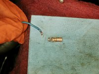
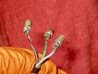
Then, it was time to re-solder the pin bushing housings back onto the ends of the wires, that had just been re-sheathed. This was a mild pain, because there was not much length of wiring to play with. I used the flattish-top of the ABS/ASR pump, with a shop rag on top, as a small "table" to do the soldering.
IMG_0050.jpeg IMG_0051.jpeg


Then I inserted the newly re-soldered wires into the black plastic housing, and re-installed the plug back onto the top of the A/C compressor. Mission accomplished for this small restoration job.
IMG_0052.jpeg IMG_0053.jpeg


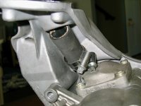
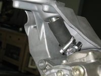
The last job of the day, I decided to do inside, at the kitchen table. It was the installation of the "short hose" between the power steering pump reservoir platform, and the intake at the top of the power steering pump. I had plenty of hose left over from my prior tandem pump rebuild job back in the 2013 or 2014 time frame, so I re-cut a new length of hose (53mm is specified for ZF pumps ... I went with a 59-60mm length) and then installed it. It was pretty straightforward, as shown in the photos below. One thing I did about half-way through the job was to flip the two clamps 180 degrees for easier accessibility once installed. I also decided to go with the factory-standard TWO clamps, rather than the FOUR clamps that I'd previously installed. I think the extra clamps needlessly compressed the short hose in the middle, where it didn't need to be.
IMG_0054.jpeg IMG_0055.jpeg IMG_0056.jpeg


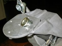
Installing the threaded top connector along with aluminum sealing ring.
IMG_0057.jpeg IMG_0058.jpeg IMG_0059.jpeg


Here's what things looked like while screwing the threaded connector down.
IMG_0060.jpeg


The top connector tube, totally installed BELOW the base surface of the power steering fluid reservoir platform.
IMG_0061.jpeg


And lastly, a couple of views of the top clamp tightened, and then both clamps tightened and in place. I'll snug them down again when I install the tandem pump and bracket onto the front of the engine, to give the clamps time to compress the hose.
IMG_0062.jpeg IMG_0063.jpeg


Thanks for your interest!

Cheers,
Gerry
 
Now, in the interest of scope creep, Gerry will be carefully disassembling 32 hydraulic lifters...


:ROFLMAO:
 
Nope.....front cylinder head covers are going on very soon with the Orange Koala-Claw® Goo™, new solenoids installed, and the engine will be turned a couple of times to ensure that the valves hit the cylinders OK ;)

Then the red valve covers go back on (after installing some assembly lube on the cam lobes). And the peripherals go back onto the front of the engine: tandem pump and bracket, smog pump, pulleys, etc.
 
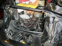
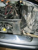
Today I received the replacement foam for the rectangular piece of foam that is found under the headlight scoop/bucket. When I removed the scoop, this 2" x 6" piece of adhesive, rectangular foam was severely disintegrated. So, I ordered a new piece of gray foam (via Amazon) of a similar spec, and will cut two pieces to the correct size, and attach them using contact cement.

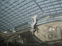
Here is the location in the headlight area where the foam is mounted (the large flat spot). Again, this is only accessible when you take the headlight out and then the bucket/scoop.
IMG_0064.jpeg IMG_0065.jpeg IMG_0066.jpeg


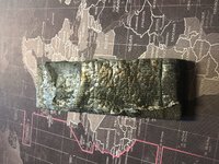
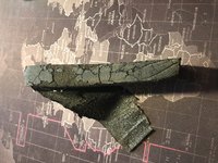
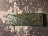
And a couple of photos of the old, disintegrating foam.
76492BA1-A409-4848-BC3F-019C7B93548A.jpeg EFF43367-CAC8-4D47-9399-68BF2420F883.jpeg E82562F9-5186-418F-9910-2A38438F36FB.jpeg
 
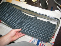
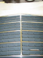
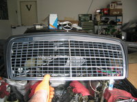
Today I spent about an hour refurbishing, cleaning, lubricating, and re-installing the grill back onto the car. It was nice and satisfying to do this. I am looking forward to the more "stock" or "traditional" look to the grill insert that the car will have.

Here's the steps that I did.

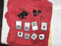
First, I soaked the grill hardware (clips and screws) for about an hour in Simple Green Motorsports cleaner to clean them up. I was surprised at the amount of grime that came off of them. Here's what the hardware looked like after coming out of the cleaner. Not perfectly sparkling, but seeing as it will be behind the grill, no one will EVER see it.
IMG_0051.jpeg


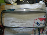
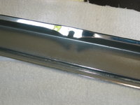
Then, I took some Griot's Garage Fine Hand Polish and polished the front chrome areas of the grill surround. It is fairly sand-blasted, but the surround doesn't have any dents, and it actually shined up pretty nicely, as you can see. The back-side and bottom side shined up, and the inside surfaces of the grill surround cleaned up well. There was no rust or other bad stuff on the grill surround.
IMG_0052.jpeg IMG_0053.jpeg


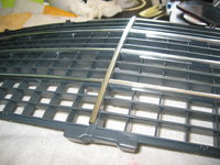
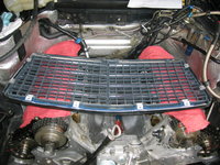
It was time to prepare the grill insert for insertion into the surround. I made sure to line everything up well and ensure the aluminum trim strips were in their proper places. Then I placed the insert down and into the grill surround.
IMG_0054.jpeg IMG_0055.jpeg IMG_0069.jpeg IMG_0070.jpeg


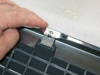
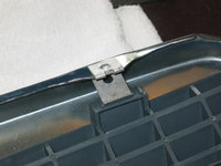
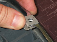
After it was placed correctly, I began inserting the eight clips that hold the insert into the surround. Everything fit nicely.
IMG_0071.jpeg IMG_0072.jpeg IMG_0073.jpeg IMG_0074.jpegIMG_0075.jpeg IMG_0076.jpeg


Then the bottom screw was inserted and tightened down into the bottom of the grill insert.
IMG_0078.jpeg


A couple of views of the grill, after preliminary assembly. Not bad.
IMG_0079.jpeg IMG_0081.jpeg


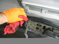
Bringing the grill out into the garage, I took some Griot's Garage "Speed Shine" on a shop towel, and cleaned the hood surface into which the grill lay. It was pretty dirty, but cleaned up well.
IMG_0082.jpeg IMG_0083.jpeg IMG_0084.jpeg


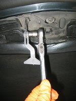
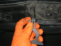
Then I removed the hood release lever, because I'd ordered a new/fresh one to replace the original lever. It is held on with a simple 10mm nut and bolt, which are left slightly loose so that the lever can slide slightly in its slot on the hood release.
IMG_0085.jpeg IMG_0086.jpeg IMG_0087.jpeg IMG_0088.jpeg


A comparison between old (left) and new (right) hood release levers. Not much discoloration or wear at all. Probably didn't need to replace it, but at $6.00 for a fresh one .......
IMG_0089.jpeg


Hood release lever installation is the reverse of removal.
IMG_0090.jpeg


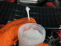
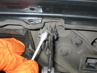
While I was at it, I lightly lubricated the hood release with some synthetic grease on a Q-Tip.
IMG_0091.jpeg IMG_0092.jpeg


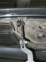
Here's the completed/installed hood release.
IMG_0094.jpeg


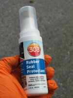
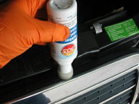
Then, before I placed the new grill into position in its' recess in the hood, I used some 303 Rubber Seal Protectant to lubricate and preserve the adhesive rubber seal that goes around the top three sides of the grill surround. I had purchased some new rubber pads (this continuous adhesive rubber strip is NLA from MB, superseded to five or six short adhesive pads), but I didn't want to use them because the rubber strip was still in very nice condition. I figured that lubricating it would help it for a few years.
IMG_0095.jpeg IMG_0096.jpeg


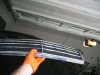
Then, it was time to place the grill insert into position, and using a 10mm socket and box-end ratcheting wrench, I inserted and tightened the eight screws that held the grill in position. It's important that you insert the hood release lever into its slot in the grill at the same time you are lowering the grill into position.
IMG_0097.jpeg IMG_0098.jpeg IMG_0099.jpeg IMG_0100.jpeg


Lastly, here is a view of the 2" x 6" foam replacement pad that I adhered to the flat area under the passenger-side headlight scoop. This was to replace the disintegrating foam that I showed in the previous post, which was really starting to crumble badly into dust. It was 1" thick foam. I bought a lot of it, so I have a lifetime supply. I also cut another piece of the same size for the driver's side, when I end up pulling that headlight and bucket to clean up that area.
IMG_0093.jpeg

Thanks for your interest !!

Cheers,
Gerry
 
This has been an increasing irritation for me over the past 10 years -- MB "substituting" pedestrian hardware, often physically with a different head type and coating, than the higher quality original hardware supplied with the car.

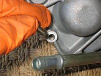
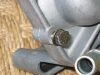
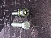
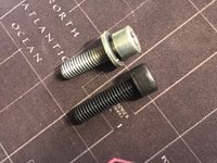
In the latest substitution/supercession, I show you the 5mm hex-head bolt. This is one of two bolts that hold the tandem pump to its mounting bracket, from the rear side. I had stripped one of these bolts in the removal, necessitating a replacement. I ordered two of the indicated replacement bolts from MB, and on my latest parts order, received this:

9DBB1BD6-476D-46C1-AE71-F45231830351.jpeg 09C408D5-1781-419C-A1FE-3B388BFC5E32.jpeg

Not acceptable, in my book. Note the dramatic difference in finishes, not to mention the head of the bolt !! I went to Home Depot and obtained as close of a substitute as I could -- a 5mm Allen bolt with a 1.25 thread pitch. Very close to original, but not exact.

29DB504E-C914-4E77-935C-F3BDE31DDDE0.jpeg A8696D3D-565D-4829-B9EF-0DFE73B2FA3A.jpeg 45AA6D19-53B0-46D5-8389-D8F62E0A656E.jpeg

That said, no one is going to ever see it, because it is on the BACK SIDE of the mounting bracket.

The only exception to this I can think of would be @JC220. I am quite certain he would not be able to sleep properly at night, unless the correct tandem pump bolt were sourced from another car, and utilised.
 
Gerry, I've run into the same problem. Sometimes the replacement is NOT functionally equivalent... i.e. missing the captive washer, or the location may be a recess where a hex-head literally will not work.

I've snagged a bunch of random bolts from junkyard engines over the years for this reason. Especially if the donor was clean and didn't have corrosion on the fasteners. Annoying part is, you don't know if MB will sell you the original or not, unless you buy one to find out.

:oldman:
 
I have huge collections of MB original hardware for the 124 and 126 from the wrecking yards as well, and I like to save everything that I replace. Unfortunately these rear-mounted tandem pump bolts don't grow on trees, and are more than I would want to deal with in obtaining from any wrecking yard car. So, I'll use the Home Depot bolt I got, with a washer, and be happy with it.

My current MB spare bolt fetish is CAN box hex bolts. When I find them when not corroded, I snag them. I have a huge bag of them. Don't know what I'll ever use them for, but I can guarantee you that no CAN box of mine will ever have rusty or corroded bolts !!
 
Well, about 15 minutes out in the shop this morning, and did a few tasks.

First, I found an apprpriate MB washer, and re-installed the two bolts that hold the tandem pump to its mounting bracket. The next step here is to re-install the bracket, and then the "S"-hose and lines to the tandem pump. I am going to try to do this after work tonight.

Next up, it is **FINALLY** time to re-install the front cylinder head covers, and the new red powder-coated valve covers, seeing as the three upper timing chain rails have been installed.

Before I get to this, however, I wanted to ensure that there is no interference between the valves and pistons, due to the timing chain work that I had done to replace the plastic chain slide rails. So, I rotated the crankshaft FOUR times (which is two complete rotations of the pistons, and FOUR rotations of the camshafts), to ensure that the chain is seating well on the new rails, and that there is no conflict between the bottoms of the valves and the tops of the pistons.

I am happy to report that with the four crank rotations, and bringing things back up to the "45" mark BTDC, as shown below -- ALL FOUR CAMS PINNED PERFECTLY. All four of the pins slid EASILY in and out of their holes. There literally is ZERO degrees off on the pointer. And more importantly, no conflict and an easy ability to rotate the crank.

Starting to rotate the crankshaft by hand, via the 27mm crank bolt....
IMG_0102.jpeg


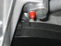
Rotating things BACK to 45 degrees Before Top Dead Center (BTDC), using the pointer and balancer numeric indicator:
IMG_0105.jpeg


Perfectly pinned camshafts !!
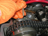
IMG_0103.jpeg IMG_0104.jpeg


Now, to begin preparing for the installation of the front cylinder head covers, I did one more final wipe-down of the sealing surfaces with a brake-cleaner-coated shop rag. Not much dirt and debris on there.
IMG_0106.jpeg


I have the head covers at the ready, since I cleaned them and installed new camshaft seals some time back. A new tube of Orange Koala-Claw® Goo™ anaerobic sealent is ready and waiting for these covers.

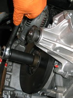
I will also re-insert the flywheel lock from underneath the car, to lock the crank. This will facilitate the torquing down of the crank bolt after I install the crankshaft pulley.

Very excited to be actually putting things back ONTO the engine and re-assembling the many many things that have been disassembled.

Thanks for your interest,
Cheers,
Gerry
 
I am happy to report that with the four crank rotations, and bringing things back up to the "45" mark BTDC, as shown below -- ALL FOUR CAMS PINNED PERFECTLY. All four of the pins slid EASILY in and out of their holes. There literally is ZERO degrees off on the pointer. And more importantly, no conflict and an easy ability to rotate the crank.
Gerry, that's with the original chain, with 150kmi - correct?

Pretty amazing that chain stretch is near zero after all that time. Supports my theory that any measured chain stretch on M119 is more likely to be from broken plastic rails, assuming no visible wear on the sprockets, and no sludge or other evidence of poor maintenance.
:wahoo:
 
That is the original chain, correct. 142K miles.

I have run full-synthetic (first the Mobil 1 black-label Yurro Car Formula back in the day, and in recent years RedLine) since I bought the car with 67K back in 2003.
 
This has been an increasing irritation for me over the past 10 years -- MB "substituting" pedestrian hardware, often physically with a different head type and coating, than the higher quality original hardware supplied with the car.

In the latest substitution/supercession, I show you the 5mm hex-head bolt. This is one of two bolts that hold the tandem pump to its mounting bracket, from the rear side. I had stripped one of these bolts in the removal, necessitating a replacement. I ordered two of the indicated replacement bolts from MB, and on my latest parts order, received this:

View attachment 108060 View attachment 108061

Not acceptable, in my book. Note the dramatic difference in finishes, not to mention the head of the bolt !! I went to Home Depot and obtained as close of a substitute as I could -- a 5mm Allen bolt with a 1.25 thread pitch. Very close to original, but not exact.
View attachment 108062 View attachment 108063 View attachment 108064

That said, no one is going to ever see it, because it is on the BACK SIDE of the mounting bracket.

The only exception to this I can think of would be @JC220. I am quite certain he would not be able to sleep properly at night, unless the correct tandem pump bolt were sourced from another car, and utilised.
Yes, IMHO, this sucks, and is completely unacceptable. Ran into the same issues when I did my top end re-fresh. Anyone have a direct link to source replacement KAMAX hardware? I did some light digging at the time, but was unsuccessful. Zinc coating FTW, IMHO.
 
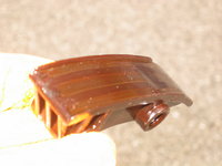
I believe that the bottom 1-1.5 inches of the right-side upper timing chain rail being broken off, was responsible for the 1-1.5-degree discrepancy in the timing chain being "off" of the 45-degree BTDC mark.

I also believe that the religious use of full-synthetic motor oil, together with frequent (5,000-mile) oil-change intervals, is in large part responsible for the lack of timing chain stretch or valvetrain wear after the 142K miles. I do not see the need for the timing chain to be replaced, at this point, before 300,000 miles.

The fact that my timing chain rail was broken well before 142K miles, despite the engine being well lubricated (and clean inside, as you can see), is a warning to EVERYONE that their rails should be changed probably around the 125K mile mark. We have had a number of members who have had broken upper rails on their M119s.

If your car has more than 150K miles on it, at a minimum you should pull the valve covers and at least CHECK the condition of the upper timing chain rails.

Timing chain, pinned at all four cams, BEFORE broken upper rail replacement:

img_0024-jpeg.107793


Timing chain, pinned at all four cams, AFTER broken upper rail replacement:

img_0105-jpeg.108113
 
Good points. If one opens their valve covers to replace something else,say the cam oilers, it is just wise to change them out as a matter of PM if they have not been done by previous owner.
 
Replacement of the two uppermost chain rails (one on each side) can easily be done after the valve covers and front cylinder head covers are removed; the exhaust cam sprockets removed; the timing chain tensioner and top timing chain guides removed; and the intake cam adjuster mechanisms removed.

The lower rail on the driver's side also requires the tandem pump + mounting bracket to be removed.

In all honesty, the lower rail on the driver's side is pretty stout, and in most cases probably DOES NOT technically have to be replaced. HOWEVER, because you've already done 85% of the work (everything excepting the tandem pump and bracket) to get at the upper rails, it really makes sense 100% of the time to ALSO do the lower rail.

I will be honest with you -- it doesn't make sense to do this job without having the special "holding" tool for the cam adjuster mechanism, which is >$100 from MB. I know that some folks have made these tools out of sockets, washers and a long bolt. I attempted to do this, myself, and I was unsuccessful at making it work. It is possible, but in my experience not probable, to be able to do this job without any type of holding tool. It may be possible to do it with a second person holding part of the cam adjuster sprocket while the second part of it is installed.

Other than the holder tool, everything just requires regular hand tools.

Also, for anyone ever doing a tandem pump removal in the future: I have removed my pump two times now. One time just removing the pump itself, and leaving the bracket attached to the front of the engine. The other time removing the bracket + pump together. I recommend to anyone who wants to remove their pump, that it is SLIGHTLY easier to remove the bracket + pump assembly together, than removing the pump alone.

The reason for this statement is:
1) The bracket is only held on the engine with THREE bolts. One bracket bolt (a 6mm Allen bolt) is easily accessible from the front of the engine. One bracket bolt (at the outside bottom edge of the driver's side cylinder head) can with not too much difficulty, also be removed from the front of the engine, leaning into the engine compartment. And the third bracket bolt can without too much difficulty be removed from under the car, with long 3/8" socket extensions, from behind the front suspension. The second and third bracket bolts are regular hex-head bolts, and easily removed (and likely not stripped) with a six-point 13mm socket.

2) The tandem pump itself is held onto the bracket/engine with FOUR bolts. Two of the tandem pump bolts are easily accessible from the front of the engine. However, the other two 6mm Allen-head tandem pump bolts hold the pump to the bracket, from the back side of the bracket. These Allen-head bolts are accessed at an awkward angle from behind the engine, and because they are Allen-head, have stronger potential to strip out (as I found above). It's simple to remove these two Allen bolts on the work-bench, once the bracket + pump assembly is removed from the engine.
 
Good points. If one opens their valve covers to replace something else,say the cam oilers, it is just wise to change them out as a matter of PM if they have not been done by previous owner.

If I do cam oilers, I do top (plastic) guides on both sides. They're stupid easy to do, and you're right there anyway. It's silly not to. Not sure I would dig into the upper guides, as that's a bit more work, since the top guides and oilers only take a couple of hours, if that. Doing the uppers involves a lot more work and some special tools. That's a big jump from valve covers and oiler tubes.

Dan
 
If I do cam oilers, I do top (plastic) guides on both sides. They're stupid easy to do, and you're right there anyway. It's silly not to. Not sure I would dig into the upper guides, as that's a bit more work, since the top guides and oilers only take a couple of hours, if that. Doing the uppers involves a lot more work and some special tools. That's a big jump from valve covers and oiler tubes.
Dan, I think the idea is to visually inspect the hard-to-replace guides while the valve cover is off. And check cam timing / "chain stretch" while you're at it.

Gerry, btw, your first photo in post #289 is backwards - should indicate a number in the low 40's (or high 30's) with broken rails or stretched chain.

:rugby:

Understood, and I heartily endorse doing so while you're in the neighborhood.

Dan
 
GVZ consider adding the update you posted About removing the bracket assembly rather than just the pump to the beginning of your HOW TO so it is a fresh update that is really helpful.
 
GVZ consider adding the update you posted About removing the bracket assembly rather than just the pump to the beginning of your HOW TO so it is a fresh update that is really helpful.
You should do a HOW-TO specifically on timing chain rail replacement, then you can enjoy the process of removing the tandem pump and bracket, and re-assembling the intake cam adjusters.
 
Dan, I think the idea is to visually inspect the hard-to-replace guides while the valve cover is off. And check cam timing / "chain stretch" while you're at it.
:rugby:

Anyone know how much stretch, as a practical matter, before it has any noticeable effect on the function of the engine?
 
Anyone know how much stretch, as a practical matter, before it has any noticeable effect on the function of the engine?
There's no formal spec in the M119 FSM, but based on specs given for 6-cyl engines, I personally would get nervous if you measured more than 6-8° at the passenger exhaust cam; and at 10° or more I'd avoid driving until it was repaired.

That said, up to 2° is normal/acceptable, and I don't lose sleep in the 2-4° range if all the rails are visually intact.

:duck:
 
Just curious, aside from jumping a sprocket, do you know if anyone has found a chain on his M119 that was at or past 6-8 degrees?
 
The spare engine I bought ~10 years ago measured 6° at the passenger exhaust sprocket. Not knowing at the time that just the rails would make so much difference, I replaced the rails AND rolled in a new chain. It pinned dead on spec (0° off) on all four cams afterwards.

One of my engines with 190k measured 4° off and had broken rails. I replaced the rails but left the chain alone, it measured <2° with new rails and old chain.

:pc1:
 
Just curious, aside from jumping a sprocket, do you know if anyone has found a chain on his M119 that was at or past 6-8 degrees?

How about 12.5 dungarees? No damage at all was likely running. (Spare engine I had bought- then rebuilt anyway and back to zero stretch)


Who has viewed this thread (Total: 1) View details

Back
Top